EP0895563B1 - Hubkolben-brennkraftmaschine - Google Patents
Hubkolben-brennkraftmaschine Download PDFInfo
- Publication number
- EP0895563B1 EP0895563B1 EP97914224A EP97914224A EP0895563B1 EP 0895563 B1 EP0895563 B1 EP 0895563B1 EP 97914224 A EP97914224 A EP 97914224A EP 97914224 A EP97914224 A EP 97914224A EP 0895563 B1 EP0895563 B1 EP 0895563B1
- Authority
- EP
- European Patent Office
- Prior art keywords
- row
- cylinders
- rows
- internal combustion
- combustion engine
- Prior art date
- Legal status (The legal status is an assumption and is not a legal conclusion. Google has not performed a legal analysis and makes no representation as to the accuracy of the status listed.)
- Expired - Lifetime
Links
- 238000002485 combustion reaction Methods 0.000 title claims description 42
- 238000009434 installation Methods 0.000 claims description 2
- 238000010304 firing Methods 0.000 description 7
- 239000007789 gas Substances 0.000 description 4
- 238000010276 construction Methods 0.000 description 2
- 230000003993 interaction Effects 0.000 description 2
- 230000015572 biosynthetic process Effects 0.000 description 1
- 230000001427 coherent effect Effects 0.000 description 1
- 239000000567 combustion gas Substances 0.000 description 1
- 230000001419 dependent effect Effects 0.000 description 1
- 230000000694 effects Effects 0.000 description 1
- 239000000463 material Substances 0.000 description 1
- 239000000203 mixture Substances 0.000 description 1
- 230000029058 respiratory gaseous exchange Effects 0.000 description 1
- 238000004904 shortening Methods 0.000 description 1
Images


Classifications
-
- F—MECHANICAL ENGINEERING; LIGHTING; HEATING; WEAPONS; BLASTING
- F02—COMBUSTION ENGINES; HOT-GAS OR COMBUSTION-PRODUCT ENGINE PLANTS
- F02B—INTERNAL-COMBUSTION PISTON ENGINES; COMBUSTION ENGINES IN GENERAL
- F02B75/00—Other engines
- F02B75/16—Engines characterised by number of cylinders, e.g. single-cylinder engines
- F02B75/18—Multi-cylinder engines
- F02B75/22—Multi-cylinder engines with cylinders in V, fan, or star arrangement
- F02B75/224—Multi-cylinder engines with cylinders in V, fan, or star arrangement with cylinders in fan arrangement
-
- F—MECHANICAL ENGINEERING; LIGHTING; HEATING; WEAPONS; BLASTING
- F02—COMBUSTION ENGINES; HOT-GAS OR COMBUSTION-PRODUCT ENGINE PLANTS
- F02B—INTERNAL-COMBUSTION PISTON ENGINES; COMBUSTION ENGINES IN GENERAL
- F02B75/00—Other engines
- F02B75/16—Engines characterised by number of cylinders, e.g. single-cylinder engines
- F02B75/18—Multi-cylinder engines
- F02B75/22—Multi-cylinder engines with cylinders in V, fan, or star arrangement
-
- F—MECHANICAL ENGINEERING; LIGHTING; HEATING; WEAPONS; BLASTING
- F02—COMBUSTION ENGINES; HOT-GAS OR COMBUSTION-PRODUCT ENGINE PLANTS
- F02B—INTERNAL-COMBUSTION PISTON ENGINES; COMBUSTION ENGINES IN GENERAL
- F02B75/00—Other engines
- F02B75/16—Engines characterised by number of cylinders, e.g. single-cylinder engines
- F02B75/18—Multi-cylinder engines
- F02B2075/1804—Number of cylinders
- F02B2075/1812—Number of cylinders three
-
- F—MECHANICAL ENGINEERING; LIGHTING; HEATING; WEAPONS; BLASTING
- F02—COMBUSTION ENGINES; HOT-GAS OR COMBUSTION-PRODUCT ENGINE PLANTS
- F02B—INTERNAL-COMBUSTION PISTON ENGINES; COMBUSTION ENGINES IN GENERAL
- F02B75/00—Other engines
- F02B75/16—Engines characterised by number of cylinders, e.g. single-cylinder engines
- F02B75/18—Multi-cylinder engines
- F02B2075/1804—Number of cylinders
- F02B2075/1832—Number of cylinders eight
-
- F—MECHANICAL ENGINEERING; LIGHTING; HEATING; WEAPONS; BLASTING
- F02—COMBUSTION ENGINES; HOT-GAS OR COMBUSTION-PRODUCT ENGINE PLANTS
- F02B—INTERNAL-COMBUSTION PISTON ENGINES; COMBUSTION ENGINES IN GENERAL
- F02B75/00—Other engines
- F02B75/16—Engines characterised by number of cylinders, e.g. single-cylinder engines
- F02B75/18—Multi-cylinder engines
- F02B2075/1804—Number of cylinders
- F02B2075/184—Number of cylinders ten
-
- F—MECHANICAL ENGINEERING; LIGHTING; HEATING; WEAPONS; BLASTING
- F02—COMBUSTION ENGINES; HOT-GAS OR COMBUSTION-PRODUCT ENGINE PLANTS
- F02B—INTERNAL-COMBUSTION PISTON ENGINES; COMBUSTION ENGINES IN GENERAL
- F02B75/00—Other engines
- F02B75/16—Engines characterised by number of cylinders, e.g. single-cylinder engines
- F02B75/18—Multi-cylinder engines
- F02B2075/1804—Number of cylinders
- F02B2075/1848—Number of cylinders twelve
Definitions
- the invention relates to a reciprocating internal combustion engine with several, along two at an angle to each other rows of cylinders according to the preamble of Claim 1.
- a generic internal combustion engine is known from DE-Z MTZ Motortechnische Zeitschrift 52, 1991, No. 3, pages 100 ff.
- the VR engine described there and produced by the applicant in large series has cylinders combined in two rows, these two rows being at a comparatively narrow fork angle to one another.
- this cylinder arrangement offers the advantage that only a single cylinder crankcase with all the cylinders combined therein in one block and only one cylinder head common to all cylinders is required. Due to the offset of the two rows of cylinders in the longitudinal direction to each other, the overall length of such a VR engine with z. B.
- a 16-cylinder engine with an H-shaped cylinder arrangement has become known from the DE book Air-Cooled Vehicle Engines, Mackerle, Jehlicka, Moebus, Franksche Verlagbuch Kunststoff Stuttgart, page 509.
- a compact arrangement is achieved here by stacking two 8-cylinder boxer engines. These each work on their own crankshaft, which, coupled together, operate a single-shaft output.
- the two opposite, 4-cylinder rows have no longitudinal offset to each other, since the two connecting rods of opposing cylinders work on a common crank pin of the crankshaft by using a connecting rod.
- pages 515 ff is another compact arrangement in an X shape known.
- two are mirror images of each other Rows of cylinders arranged in a V-shape to each other, all of which are not restricted
- the crank mechanism works with a common crankshaft, i.e. all cylinder longitudinal axes intersect the crankshaft's central longitudinal axis.
- the crankshaft only points four offsets since there is a main connecting rod with three secondary connecting rods on each of these crank pins works, i.e. the four rows of cylinders have no longitudinal offset to each other on.
- the invention has for its object a generic reciprocating internal combustion engine with several, at an angle to each other and a longitudinal offset to each other having cylinders in such a way that under stress a construction space as small as possible, a compact arrangement of a comparatively large one Number of cylinders is made possible.
- the aim is to ensure a fresh air supply or the discharge of the exhaust gases, as well as a perfect drive of the gas exchange Gas exchange valves can be guaranteed.
- the invention solves this problem in a generic internal combustion engine by an arrangement of two further, also V-shaped rows of cylinders, one of these rows of cylinders being arranged in the V-space between the first and second rows and the further, fourth row outside this V-space lies, whereby the cylinders of all rows work on a common crankshaft.
- the even number of rows of cylinders also ensures a symmetrical arrangement of lines for the air supply and for exhaust gases.
- this provides the basis for a modular construction of a series of internal combustion engines of the same type with different numbers of cylinders while maintaining the fundamentally compact arrangement and while maintaining existing lines. Both even and odd number of cylinders can be used in each row.
- An advantageous embodiment is to achieve a comparatively simple structure provided that the additional, third and fourth rows are longitudinally offset from one another and to the first two rows of cylinders.
- uniform connecting rods can be used.
- the between the first and second row of cylinders and the fork angles formed between the third and fourth row of cylinders are identical in size and that is the V-spaces formed by this fork angle by a certain cylinder angle are arranged rotated to each other.
- This cylinder angle is chosen so that the first and third or second and fourth rows mirror-symmetrical with respect to the other two rows to one Crankshaft receiving center plane of the internal combustion engine. Under the assumption a perpendicular center plane thus results on both sides of this plane each cylinder rows arranged in a V-shape, the cylinder angle within this V-shaped rows is chosen to be comparatively small.
- crank mechanism of this internal combustion engine is limited, that is Cylinder axes of the two rows on one side of the median plane intersect vertical arrangement of the median plane below this and on the opposite Page. This further shortens the internal combustion engine by pushing one into the other of the cylinders assigned to the two rows.
- each crank has two connecting rods offset from one another.
- the connecting rods of two work around the fork angle offset cylinders of the first and third or second and fourth rows.
- the cylinder rows each have three cylinders and the other two each have two cylinders.
- the rows with the larger number of cylinders are preferably offset from one another by the fork angle.
- control drive of the Internal combustion engine can have the two combined rows of cylinders on each side the central plane can be made identical overall, which creates further advantageous effects in terms of component expense, assembly, etc. can be achieved.
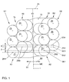
- a reciprocating piston internal combustion engine hereinafter referred to only as an internal combustion engine, has a total of four rows R1, R2, R3, R4 of cylinders, two of these rows R1, R3 and R2, R 4 being arranged on one of the two sides S1, S2 of a central plane ME are, which receives a crankshaft axis 1.
- the row R1 assigned to the side S1 and the row R2 assigned to the side S2 are V-shaped to one another at a fork angle ⁇ 1 and thus define a first V-space V1 between them.
- the two further cylinder rows R3 and R4 are assigned to the sides S1 and S2 and are at a fork angle ⁇ 2, defining another V-space V2, to one another.
- the third row R3 is in the first V-space V1, while the fourth row R4 is arranged outside of this space V1.
- the rows R1 and R3 lying on the side S1 are combined to form a group G1, cylinder axes ZR1 of the first row and cylinder axes ZR3 of the third row again being at a V-shaped cylinder angle ⁇ G1 to one another.
- the size of the fork angles ⁇ 1 and ⁇ 2 is chosen to be identical, as is the size of the cylinder angles ⁇ G1 and ⁇ G2, the entire arrangement with respect to the central plane ME being such that the groups G1 and G2 are each symmetrical to this central plane ME and thereby the rows R1, R3 and R2, R4 of these groups G1 and G2 are each arranged mirror-symmetrically to this plane ME.
- cylinder axes ZR1 and ZR3 have respectively ZR2 and ZR4 are identical to each other along the crankshaft axis 1 Row offset 2 on.
- the two groups G1 and G2 in turn have a group offset 3 along this crankshaft axis 1.
- the cylinder axes ZR1 to ZR4 thus each lie in one of four sectional planes SE1 to SE4 formed perpendicular to the central plane ME.
- the cylinders Z1 and Z3 are assigned to the first row R1, the cylinders Z2 and Z4 to the third row R3, the cylinders Z5 and Z7 to the second row R2 and the cylinders Z6 and Z8 to the fourth row R4.
- a crankshaft 4 of the internal combustion engine has a total of four crankings 5, 6, 7, 8 and is supported in a total of five main bearings 9 of a crankcase 10.
- two cylinders each work on one of the cranks by means of the connecting rods 11 assigned to them, the two conrod bearings 12, 13 of a crank having an offset by a difference angle ⁇ winkel.
- the cylinders which are staggered relative to each other by the group offset 3 and are assigned to one of the V-spaces V1 or V2, work on one of the offsets.
- the connecting rods 11 of the cylinders Z1 and Z5 lying in the sectional planes SE1 and SE2 are spaced apart from one another by the offset 3 in the crank 5. Between the connecting rods 11 of cylinders Z5 and Z6 lying in the sectional plane SE2 and SE4 there is the row offset 2, usually referred to as the cylinder spacing.
- the crank mechanism of the internal combustion engine is designed to be limited, that is to say the cylinder axes ZR1, ZR3 or ZR2, ZR4, which are at an angle to one another by the cylinder angle ⁇ G1 or ⁇ G2, do not intersect with the crankshaft axis 1 Intersection SP1 of the first group G1 on the side S2 on the side of the transverse plane QE facing away from the rows R1 and R3.
- another intersection point SP2 of the second group G2 lies in mirror image with respect to the center plane ME. Because of the cranking of the crank mechanism, the maximum extension positions of the connecting rods 11 at top and bottom dead center OT and UT do not coincide with the respective cylinder axis ZR.
- crank angle ⁇ occurring during the rotation of the crankshaft 4 is counted by the crankshaft axis 1, based on an unrestricted crank drive from a parallel 13 to the cylinder axis ZR, then TDC and TDC are achieved with a crank angle offset of ⁇ *. Due to the position of the intersection points SP1 and SP2 with respect to the transverse plane QE on the side facing away from the groups G1 and G2, a positive or negative setpoint is set, so that the bottom dead center UT and the top dead center OT after more or less than 180 ° crank angle ⁇ follows.
- the selected setting enables the space to be moved closer together Cylinders within groups G1 and G2, so that the respective cylinders of these groups G1 and G2 are cast together in a common cylinder block 15 and 16, respectively can. These are common to one of the two rows of cylinders in a group Cylinder head 17 or 18 covered.
- the interaction of the previously explained 8-cylinder arrangement is briefly based on one Numerical example explained.
- the fork angles ⁇ 1 and ⁇ 2 are 72 °, the cylinder angles ⁇ G1 and ⁇ G2 each 15 °. Due to the symmetrical arrangement to the central plane ME the cylinder angles ⁇ G1 and ⁇ G2 also arise with respect to the bisector 19 the fork angle ⁇ 1 or ⁇ 2. Because of the four offsets 5 to lying on two levels 8 there is an ignition sequence between the individual cylinders at a crank angle of 90 ° ⁇ a. With a selected firing order in the order Z1-Z5-Z4-Z8-Z6-Z3-Z7-Z2, 2 in the crank star 20 according to FIG.
- the offset within the individual Cranks 5 to 8 are dispensed with.
- the rows R3 and R4 are three each Cylinder assigned, while the rows R1 and R2 each carry two cylinders. While here the previously described mirror-image arrangement of the angular positions mentioned the middle plane ME is preserved, the arrangement of the rows is not a mirror image, because on the three-cylinder row R3 lying on the side S1 initially has one on the side S2 two-cylinder row R2 follows.
- a flywheel 25 is assigned to the crankshaft 4 on the output side. Adjacent to this is a chain drive for driving camshafts 27 and 28 of group G1 and camshafts 29 and 30 of group G2 arranged. These operate via cams 31 and 32 as Lift valves designed intake valves 33 and exhaust valves 34 with the interposition of Roller rocker arms 35, four lift valves being assigned to each cylinder Z1 to Z8.
- An air intake system for ventilating the combustion chambers 40 of the internal combustion engine is essentially symmetrical to the central plane ME and is provided with collecting volumes 37 and 38 formed above the groups G1 and G2. Combustion air is fed via suction pipes 41 from the above-mentioned collecting volumes 37, 38 to inlet channels 41, all inlet channels 41 of a group G1 or G2 each opening into a flange 42 which is formed on the row R3 or R2 facing the central plane ME. All outlet channels 43 of the respective group G1 or G2 are led to flanges 44 of the rows R1 and R4, which are external to the central plane ME.
- the cylinder blocks 15 and 16 are in one piece and of the same material as the crankcase 10 formed, the outer walls 45 in the region of the crankshaft axis 1 are drawn across the transverse plane QE.
Landscapes
- Engineering & Computer Science (AREA)
- Chemical & Material Sciences (AREA)
- Combustion & Propulsion (AREA)
- Mechanical Engineering (AREA)
- General Engineering & Computer Science (AREA)
- Cylinder Crankcases Of Internal Combustion Engines (AREA)
- Shafts, Cranks, Connecting Bars, And Related Bearings (AREA)
Description
Die Zylinderbänke dieses Motors weisen einen Gabelwinkel von 15° zueinander auf und die jeweils drei Zylinderachsen einer Zylinderreihe liegen in einer gemeinsamen Ebene, welche sich in einem Abstand von 12,5 mm unterhalb der Kurbelwelle schneiden. Dieser geschränkte Kurbeltrieb führt zu einer weiteren Verkürzung des Motors.
Bezüglich der Geometrie des Kurbeltriebes und der verwendeten Kurbelwellenkröpfungslagen sowie der Zündfolgen sei auf die DE-Z MTZ, Motortechnische Zeitschrift 51, 1990, Nr. 10 verwiesen, welche sich detailliert mit diesem VR-Motorkonzept auseinandersetzt und dabei auch Vorschläge bezüglich der Verwendung von einer, zwei oder drei Nockenwellen im gemeinsamen Zylinderkopf zur Betätigung von jeweils zwei oder vier Ventilen je Brennraum unterbreitet.
So ist aus dem DE-Buch Luftgekühlte Fahrzeugmotoren, Mackerle, Jehlicka, Moebus, Franksche Verlagsbuchhandlung Stuttgart, Seite 509, ein 16-zylindriger Motor mit H-förmiger Zylinderanordnung bekannt geworden. Eine kompakte Anordnung wird hier durch das Übereinanderanordnen von zwei 8-zylindr- igen Boxerbrennkraftmaschinen erzielt. Diese arbeiten jeweils auf eine eigene Kurbelwelle, welche aneinander gekoppelt einen einwelligen Abtrieb bedienen. Die beiden sich jeweils gegenüberliegenden, 4-zylindrigen Reihen weisen keinen Längsversatz zueinander auf, da die beiden Pleuel von sich gegenüberliegenden Zylindern durch die Verwendung eines Gabelpleuels auf einen gemeinsamen Hubzapfen der Kurbelwelle arbeiten.
Problematisch bei einer solchen Anordnung ist die gleichmäßige Versorgung der den Zylindern zugeordneten Brennräume mit Frischgemisch sowie die Abfuhr der Verbrennungsgase, da sich in dem V-Raum auf einer Seite der horizontalen Ebene nur Einlaßkanäle für zwei Zylinderreihen befinden, während auf der anderen Seite in diesem V-Raum die einer der Zylinderreihen zugeordneten Einlaßkanäle und die Auslaßkanäle der anderen Zylinderreihe angeordnet werden müssen.
Vorteilhafte Ausgestaltungen der Erfindung sind in den abhängigen Ansprüchen angegeben.
Weiterhin ist hiermit die Grundlage für einen baukastenartigen Aufbau einer Reihe von gleichartigen Brennkraftmaschinen mit unterschiedlicher Zylinderanzahl unter Wahrung der grundsätzlich kompakten Anordnung und unter Beibehaltung von vorhandenen Leitungen gegeben. Hierbei können sowohl gradzahlige wie auch ungradzahlige Zylinderanzahlen in jeder Reihe zur Anwendung kommen.
Bevorzugt ist dabei zur Verwendung möglichst gleicher Teile und zur Erzielung einer symmetrischen Anordnung vorgesehen, die Reihen mit der größeren Anzahl von Zylindern um den Gabelwinkel zueinander versetzt anzuordnen.
Es zeigen:
Die der Seite S1 zugeordnete Reihe R1 und die der Seite S2 zugeordnete Reihe R2 stehen unter einem Gabelwinkel δ1 V-förmig zueinander und definieren zwischen sich somit einen ersten V-Raum V1.
In analoger Weise sind die beiden weiteren Zylinderreihen R3 und R4 den Seiten S1 und S2 zugeordnet und stehen unter einem Gabelwinkel δ2, einen weiteren V-Raum V2 definierend, zueinander. Somit steht die dritte Reihe R3 in dem ersten V-Raum V1, während die vierte Reihe R4 außerhalb dieses Raumes V1 angeordnet ist.
Die Größe der Gabelwinkel δ1 und δ2 ist dabei identisch gewählt ebenso wie die Größe der Zylinderwinkel αG1 und αG2, wobei die gesamte Anordnung bezüglich der Mittelebene ME so getroffen ist, daß die Gruppen G1 und G2 jeweils symmetrisch zu dieser Mittelebene ME liegen und dadurch die Reihen R1, R3 bzw. R2, R4 dieser Gruppen G1 bzw. G2 jeweils spiegelsymmetrisch zu dieser Ebene ME angeordnet sind.
Die Zylinderachsen ZR1 bis ZR4 liegen somit jeweils in einer von vier senkrecht zur Mittelebene ME ausgebildeten Schnittebenen SE1 bis SE4.
Eine Kurbelwelle 4 der Brennkraftmaschine weist insgesamt vier Kröpfungen 5, 6, 7, 8 auf und ist in insgesamt fünf Hauptlagern 9 eines Kurbelgehäuses 10 abgestützt. Zur Erzielung einer gleichmäßigen und komfortablen Zündfolge arbeiten jeweils zwei Zylinder mittels der ihnen zugeordneten Pleuel 11 auf eine der Kröpfungen, wobei die beiden Pleuellager 12, 13 einer Kröpfung einen Versatz um einen Differenzwinkel Δϕ aufweisen.
Die jeweils um den Gruppenversatz 3 zueinander gestaffelten und einem der V-Räume V1 bzw. V2 zugeordneten Zylinder arbeiten auf eine der Kröpfungen. Somit sind die Pleuel 11 der Zylinder Z1 und Z5 mit der Kröpfung 5, die Zylinder Z2 und Z6 mit der Kröpfung 6, die Zylinder Z3 und Z7 mit der Kröpfung 7 und die Zylinder Z4 und Z8 mit der Kröpfung 8 verbunden. Wie aus Figur 2, rechts ersichtlich, sind die in den Schnittebenen SE1 und SE2 liegenden Pleuel 11 der Zylinder Z1 und Z5 in der Kröpfung 5 um den Gruppenversatz 3 zueinander beabstandet. Zwischen den in der Schnittebene SE2 und SE4 liegenden Pleueln 11 von Zylinder Z5 und Z6 liegt der, üblicherweise als Zylinderabstand bezeichnete, Reihen versatz 2 vor.
Aufgrund der Schränkung des Kurbeltriebes fallen die maximalen Strecklagen der Pleuel 11 im oberen bzw. unteren Totpunkt OT bzw. UT nicht mit der jeweiligen Zylinderachse ZR zusammen. Wird der während der Drehung der Kurbelwelle 4 auftretende Kurbelwinkel ϕ in Anlehnung an einen ungeschränkten Kurbeltrieb von einer Parallelen 13 zur Zylinderachse ZR durch die Kurbelwellenachse 1 ausgezählt, so werden OT und UT bei einem Kurbelwinkelversatz von ϕ* erreicht. Aufgrund der Lage der Schnittpunkte SP1 und SP2 bezüglich der Querebene QE auf der von den Gruppen G1 bzw. G2 abgewandten Seite stellt sich eine positive oder negative Schränkung ein, so daß der untere Totpunkt UT dem oberen Totpunkt OT nach mehr oder weniger als 180° Kurbelwinkel ϕ folgt.
Eine Luftansauganlage zur Beatmung der Brennräume 40 der Brennkraftmaschine ist im wesentlichen symmetrisch zur Mittelebene ME und mit oberhalb der Gruppen G1 und G2 ausgebildeten Sammelvolumina 37 und 38 versehen. Verbrennungsluft wird über Saugrohre 41 aus den erwähnten Sammelvolumina 37, 38 zu Einlaßkanälen 41 geführt, wobei alle Einlaßkanäle 41 einer Gruppe G1 bzw. G2 in je einen Flansch 42 münden, welcher an der Reihe R3 bzw. R2 der Mittelebene ME zugewandt ausgebildet ist. Alle Auslaßkanäle 43 der jeweiligen Gruppe G1 oder G2 sind zu bezüglich der Mittelebene ME außenliegenden Flanschen 44 der Reihen R1 bzw. R4 geführt.
Claims (12)
- Hubkolben-Brennkraftmaschine mit einer ersten und einer zweiten V-förmig zueinanderstehenden Reihe (R1 und R2) von Zylindern, welche entlang einer der Reihen (R1, R2) gegenüber den Zylindern der anderen Reihe (R2, R1) in Längsrichtung der Brennkraftmaschine versetzt angeordnet sind, und mit zwei weiteren, V-förmig zueinander stehenden dritten und vierten Reihen (R3 und R4) von Zylindern, deren eine (R3) in dem Bauraum (V1) zwischen der ersten und zweiten Reihe (R1 und R2) und deren andere (R4) außerhalb dieses V-Raumes (V1) angeordnet ist, wobei alle Zylinder (Z1 bis Z8) mit einer gemeinsamen Kurbelwelle (4) verbunden sind,
dadurch gekennzeichnet, daß
die Zylinderachsen (ZR1, ZR2) der ersten und zweiten Reihe (R1 und R2) in senkrecht zu einer die Kurbelwelle (4) aufnehmenden Mittelebene (ME) verlaufenden Schnittebenen (SE1, SE2) liegend angeordnet sind, welche in Richtung der Kurbelwellenachse (1) um einen identischen Gruppenversatz (3) zueinander beabstandet sind und die Zylinderachsen (ZR2, ZR4) der zweiten und vierten Reihe (R2 und R4) in senkrecht zu der Mittelebene (ME) verlaufenden Schnittebenen (SE2, SE4) liegend angeordnet sind, welche um einen identischen Reihenversatz (2) zueinander beabstandet sind, und die die Zylinderachsen (ZR2) der zweiten Reihe (R2) aufnehmende Schnittebene (SE2) zwischen den die Zylinderachsen (ZR1 und ZR3) der ersten und dritten Reihe (R1 und R3) aufnehmenden Schnittebenen (SE1 und SE3) verläuft. - Brennkraftmaschine nach Anspruch 1,
dadurch gekennzeichnet, daß
der Reihenversatz (2) größer gewählt ist als der Gruppenversatz (3). - Brennkraftmaschine nach Anspruch 2,
dadurch gekennzeichnet, daß
die zwischen der ersten und zweiten Reihe (R1 und R2) und der dritten und vierten Reihe (R3 und R4) gebildeten Gabelwinkel (δ1 und δ2) identisch groß sind und daß die durch diese Gabelwinkel (δ1, δ2) gebildeten V-Räume (V1, V2) um einen Zylinderwinkel (αG1, αG2) derart zueinander verdreht angeordnet sind, daß die unter diesem Zylinderwinkel (αG1) zueinanderstehende erste und dritte Reihe (R1 und R3) spiegelsymmetrisch bezüglich der zweiten und vierten Reihe (R2 und R4) zu der Mittelebene (ME) der Brennkraftmaschine liegen. - Brennkraftmaschine nach Anspruch 3,
dadurch gekennzeichnet, daß
sich die Zylinderachsen (ZR1, ZR3 und ZR2, ZR4) der jeweils auf einer Seite (S1 und S2) der Mittelebene (ME) angeordneten Reihen (R1, R3 und R2, R4) schneiden, wobei die Schnittpunkte (SP1 und SP2) bezüglich einer senkrecht zur Mittelebene (ME) durch die Kurbelwellenachse (1) verlaufenden Querebene (QE) auf der von den Reihen (R1 bis R4) abgewandten Seite dieser Querebene (QE) und auf der gegenüberliegenden Seite (S2 und S1) der Mittelebene (ME) liegen. - Brennkraftmaschine nach Anspruch 3 oder 4,
dadurch gekennzeichnet, daß
die Zylinderanzahl ein ganzzahliges Vielfaches der Anzahl der Reihen von Zylindern beträgt und dabei jeweils zwei um den Gabelwinkel (δ1, δ2) zueinander versetzte Zylinder (Z1 und Z5) der ersten und zweiten Reihe (R1 und R2) beziehungsweise (Z2 und Z6) der dritten und vierten Reihe (R3 und R4) mit einer gemeinsamen, versetzten Kröpfung (5 bzw. 6) der Kurbelwelle (4) verbunden sind. - Brennkraftmaschine nach Anspruch 3 oder 4,
dadurch gekennzeichnet, daß
zumindest zwei (R3, R4) der Reihen eine identische, größere Anzahl von Zylindern aufweisen als die beiden anderen Reihen (R1, R2). - Brennkraftmaschine nach Anspruch 6,
dadurch gekennzeichnet, daß
die Reihen (R3, R4) mit der größeren Anzahl um den Gabelwinkel (δ1, δ2) zueinander versetzt sind. - Brennkraftmaschine nach einem oder mehreren der vorhergehenden Ansprüche 1 bis 7,
dadurch gekennzeichnet, daß
der zwischen der ersten und der dritten bzw. der zweiten und der vierten Reihe (R1 und R3 bzw. R2 und R4) gebildete Zylinderwinkel (αG1 bzw. αG2) vergleichsweise klein gewählt ist, so daß die zu einer ersten Gruppe (G1) zusammengefaßten Zylinder (Z1 bis Z4) der Reihen (R1 und R3) zu einem einstückigen Zylinderblock (15) zusammengefaßt und die anderen Zylinder (Z5 bis Z8) zu einem ebensolchen Zylinderblock (16) einer zweiten Gruppe (G2) zusammengefaßt sind. - Brennkraftmaschine nach einem oder mehreren der vorhergehenden Ansprüche 1 bis 8,
dadurch gekennzeichnet, daß
der zwischen der ersten und zweiten Reihe (R1 und R2) bzw. der dritten und vierten Reihe (R3 und R4) ausgebildete Gabelwinkel (δ1 bzw. δ2) zwischen 60° und 90° beträgt, vorzugsweise 72°. - Brennkraftmaschine nach Anspruch 9,
dadurch gekennzeichnet, daß
der zwischen den Zylindern der ersten Reihe (R1) und der dritten Reihe (R3) bzw. der zweiten Reihe (R2) und der vierten Reihe (R4) auftretende Zylinderwinkel (αG1 bzw. αG2) zwischen 10° und 20° beträgt, vorzugsweise 15°. - Brennkraftmaschine nach Anspruch 5 oder 6,
dadurch gekennzeichnet, daß
die um den Gruppenversatz (3) zueinander beabstandet liegenden Zylinderachsen (ZR1, ZR2) auf eine gemeinsame Kröpfung (5) der Kurbelwelle (4) arbeiten. - Brennkraftmaschine nach Anspruch 5 oder 6,
dadurch gekennzeichnet, daß
die um den Reihenversatz (2) zueinander beabstandeten Zylinderachsen (ZR2, ZR4) jeweils auf eine eigene Kröpfung (5, 6) der Kurbelwelle (4) arbeiten.
Applications Claiming Priority (3)
| Application Number | Priority Date | Filing Date | Title |
|---|---|---|---|
| DE19616030 | 1996-04-23 | ||
| DE19616030 | 1996-04-23 | ||
| PCT/EP1997/001239 WO1997040267A1 (de) | 1996-04-23 | 1997-03-12 | Hubkolben-brennkraftmaschine |
Publications (2)
| Publication Number | Publication Date |
|---|---|
| EP0895563A1 EP0895563A1 (de) | 1999-02-10 |
| EP0895563B1 true EP0895563B1 (de) | 1999-11-03 |
Family
ID=7792106
Family Applications (1)
| Application Number | Title | Priority Date | Filing Date |
|---|---|---|---|
| EP97914224A Expired - Lifetime EP0895563B1 (de) | 1996-04-23 | 1997-03-12 | Hubkolben-brennkraftmaschine |
Country Status (6)
| Country | Link |
|---|---|
| EP (1) | EP0895563B1 (de) |
| JP (1) | JP2000508736A (de) |
| DE (2) | DE59700667D1 (de) |
| ES (1) | ES2140224T3 (de) |
| PT (1) | PT895563E (de) |
| WO (1) | WO1997040267A1 (de) |
Families Citing this family (8)
| Publication number | Priority date | Publication date | Assignee | Title |
|---|---|---|---|---|
| WO2000008324A1 (de) * | 1998-08-07 | 2000-02-17 | Daimlerchrysler Ag | Brennkraftmaschine |
| FR2845422B1 (fr) * | 2002-10-04 | 2004-12-17 | Olivier Lhuillier | Moteur a combustion interne a 4 temps a chaine cinematique en"w" |
| DE102004021360B4 (de) * | 2004-04-30 | 2009-03-19 | Audi Ag | Brennkraftmaschine mit Zylinderpaaren |
| DE102004042765B4 (de) * | 2004-09-05 | 2007-07-19 | Clemens Neese | Kraftrad mit einer platz- und gewichtsparenden Motoranordnung |
| DE102008047719B4 (de) * | 2008-09-18 | 2011-03-10 | Dieter Hartmann-Wirthwein | Kurbeltrieb für Vierzylinderverbrennungsmotoren |
| DE102010021613B4 (de) * | 2010-05-26 | 2012-06-21 | Horex Gmbh | Kraftrad mit kompakter Verbrennungskraftmaschine |
| DE102016117251B4 (de) | 2016-09-14 | 2019-08-22 | Iav Gmbh Ingenieurgesellschaft Auto Und Verkehr | Kraftrad mit kompakter Hubkolbenbrennkraftmaschine |
| DE102016015112A1 (de) | 2016-12-20 | 2018-06-21 | Deutz Aktiengesellschaft | Brennkraftmaschine mit teilweiser Kolbenschränkung |
Family Cites Families (4)
| Publication number | Priority date | Publication date | Assignee | Title |
|---|---|---|---|---|
| FR490351A (fr) * | 1917-12-17 | 1919-04-19 | Gaston Mougeotte | Moteur à explosions sans soupapes, à groupes de cylindres en éventail |
| US1407336A (en) * | 1918-07-15 | 1922-02-21 | Harvey J Sallee | Internal-combustion engine |
| FR1024825A (fr) * | 1950-09-22 | 1953-04-07 | Perfectionnements apportés aux moteurs à combustion interne | |
| FR1430302A (fr) * | 1965-01-20 | 1966-03-04 | Westinghouse Freins & Signaux | Perfectionnements apportés aux machines tournantes à pistons alternatifs, pour équilibrer les forces d'inertie secondaires |
-
1997
- 1997-03-12 PT PT97914224T patent/PT895563E/pt unknown
- 1997-03-12 JP JP9537641A patent/JP2000508736A/ja active Pending
- 1997-03-12 EP EP97914224A patent/EP0895563B1/de not_active Expired - Lifetime
- 1997-03-12 DE DE59700667T patent/DE59700667D1/de not_active Expired - Lifetime
- 1997-03-12 ES ES97914224T patent/ES2140224T3/es not_active Expired - Lifetime
- 1997-03-12 WO PCT/EP1997/001239 patent/WO1997040267A1/de not_active Ceased
- 1997-04-18 DE DE19716274A patent/DE19716274B4/de not_active Expired - Lifetime
Also Published As
| Publication number | Publication date |
|---|---|
| ES2140224T3 (es) | 2000-02-16 |
| PT895563E (pt) | 2000-04-28 |
| DE19716274A1 (de) | 1997-10-30 |
| DE59700667D1 (de) | 1999-12-09 |
| WO1997040267A1 (de) | 1997-10-30 |
| JP2000508736A (ja) | 2000-07-11 |
| EP0895563A1 (de) | 1999-02-10 |
| DE19716274B4 (de) | 2012-05-24 |
Similar Documents
| Publication | Publication Date | Title |
|---|---|---|
| DE1751736C2 (de) | Mehrzylindrige Kraftstoffeinspritzpumpe für Brennkraftmaschinen | |
| DE112011102483T5 (de) | Kurbelwelle für eine Brennkraftmaschine | |
| DE60201976T2 (de) | Flugzeugtriebwerk mit luft- und wassergekühlten gegenüberliegenden zylindern | |
| DE60221452T2 (de) | Kolbenbetätigung einer V-Typ-Brennkraftmaschine mit variablem Verdichtungsverhältnis | |
| DE69514148T2 (de) | Abgassystem für Motor | |
| DE2047180A1 (de) | Kolbentriebwerk | |
| DE19716274B4 (de) | Hubkolben-Brennkraftmaschine | |
| EP1789664B1 (de) | Kraftrad mit kompakter verbrennungskraftmaschine | |
| DE102013204792A1 (de) | Kurbelwelle für einen Verbrennungsmotor | |
| DE2727056A1 (de) | Einrichtung fuer gegossene motorbloecke fuer wassergekuehlte zweitaktmotoren | |
| DE69419913T2 (de) | Induktionssystem einer internen brennkraftmaschine | |
| DE2918347A1 (de) | Stirlingmotor | |
| DE3935883C2 (de) | Viertakt-Dieselbrennkraftmaschine | |
| DE1933271C3 (de) | Saugrohranordnung für Brennkraftmaschinen | |
| DE102013201840A1 (de) | Kurbelwelle für einen Verbrennungsmotor | |
| DE69408384T2 (de) | Brennkraftmaschine | |
| DE1751672A1 (de) | Brennkraftmaschine | |
| WO2024033225A1 (de) | Tangential-verbrennungsmotor | |
| DE4212110A1 (de) | Dieselbrennkraftmaschine | |
| DE2942033C2 (de) | ||
| DE4443707A1 (de) | Schwingungsarme Dreizylinder-Reihen-Brennkraftmaschine | |
| DE2943560C2 (de) | Vorrichtung für einen Verbrennungsmotor | |
| EP4321727B1 (de) | Tangential-verbrennungsmotor | |
| DE102016226216B4 (de) | Verbrennungsmotor mit einem ladeluftkühler mit kammerpartition | |
| EP3268624B1 (de) | Kurbelwelle für eine reihenzylinder-brennkraftmaschine sowie eine reihenzylinder-brennkraftmaschine |
Legal Events
| Date | Code | Title | Description |
|---|---|---|---|
| PUAI | Public reference made under article 153(3) epc to a published international application that has entered the european phase |
Free format text: ORIGINAL CODE: 0009012 |
|
| 17P | Request for examination filed |
Effective date: 19980924 |
|
| AK | Designated contracting states |
Kind code of ref document: A1 Designated state(s): DE ES FR GB IT PT |
|
| GRAG | Despatch of communication of intention to grant |
Free format text: ORIGINAL CODE: EPIDOS AGRA |
|
| GRAG | Despatch of communication of intention to grant |
Free format text: ORIGINAL CODE: EPIDOS AGRA |
|
| GRAH | Despatch of communication of intention to grant a patent |
Free format text: ORIGINAL CODE: EPIDOS IGRA |
|
| 17Q | First examination report despatched |
Effective date: 19990323 |
|
| GRAH | Despatch of communication of intention to grant a patent |
Free format text: ORIGINAL CODE: EPIDOS IGRA |
|
| GRAA | (expected) grant |
Free format text: ORIGINAL CODE: 0009210 |
|
| AK | Designated contracting states |
Kind code of ref document: B1 Designated state(s): DE ES FR GB IT PT |
|
| REF | Corresponds to: |
Ref document number: 59700667 Country of ref document: DE Date of ref document: 19991209 |
|
| ET | Fr: translation filed | ||
| ITF | It: translation for a ep patent filed | ||
| GBT | Gb: translation of ep patent filed (gb section 77(6)(a)/1977) |
Effective date: 20000121 |
|
| REG | Reference to a national code |
Ref country code: ES Ref legal event code: FG2A Ref document number: 2140224 Country of ref document: ES Kind code of ref document: T3 |
|
| REG | Reference to a national code |
Ref country code: PT Ref legal event code: SC4A Free format text: AVAILABILITY OF NATIONAL TRANSLATION Effective date: 20000128 |
|
| PLBE | No opposition filed within time limit |
Free format text: ORIGINAL CODE: 0009261 |
|
| STAA | Information on the status of an ep patent application or granted ep patent |
Free format text: STATUS: NO OPPOSITION FILED WITHIN TIME LIMIT |
|
| 26N | No opposition filed | ||
| REG | Reference to a national code |
Ref country code: GB Ref legal event code: IF02 |
|
| REG | Reference to a national code |
Ref country code: DE Ref legal event code: R084 Ref document number: 59700667 Country of ref document: DE Effective date: 20111008 |
|
| PGFP | Annual fee paid to national office [announced via postgrant information from national office to epo] |
Ref country code: IT Payment date: 20120322 Year of fee payment: 16 |
|
| PGFP | Annual fee paid to national office [announced via postgrant information from national office to epo] |
Ref country code: ES Payment date: 20120427 Year of fee payment: 16 |
|
| PGFP | Annual fee paid to national office [announced via postgrant information from national office to epo] |
Ref country code: DE Payment date: 20130331 Year of fee payment: 17 |
|
| PGFP | Annual fee paid to national office [announced via postgrant information from national office to epo] |
Ref country code: PT Payment date: 20130308 Year of fee payment: 17 |
|
| REG | Reference to a national code |
Ref country code: PT Ref legal event code: MM4A Free format text: LAPSE DUE TO NON-PAYMENT OF FEES Effective date: 20140912 |
|
| REG | Reference to a national code |
Ref country code: DE Ref legal event code: R119 Ref document number: 59700667 Country of ref document: DE |
|
| PG25 | Lapsed in a contracting state [announced via postgrant information from national office to epo] |
Ref country code: PT Free format text: LAPSE BECAUSE OF NON-PAYMENT OF DUE FEES Effective date: 20140912 |
|
| REG | Reference to a national code |
Ref country code: DE Ref legal event code: R119 Ref document number: 59700667 Country of ref document: DE Effective date: 20141001 |
|
| PG25 | Lapsed in a contracting state [announced via postgrant information from national office to epo] |
Ref country code: DE Free format text: LAPSE BECAUSE OF NON-PAYMENT OF DUE FEES Effective date: 20141001 |
|
| PG25 | Lapsed in a contracting state [announced via postgrant information from national office to epo] |
Ref country code: IT Free format text: LAPSE BECAUSE OF NON-PAYMENT OF DUE FEES Effective date: 20140312 |
|
| REG | Reference to a national code |
Ref country code: ES Ref legal event code: FD2A Effective date: 20150424 |
|
| PG25 | Lapsed in a contracting state [announced via postgrant information from national office to epo] |
Ref country code: ES Free format text: LAPSE BECAUSE OF NON-PAYMENT OF DUE FEES Effective date: 20140313 |
|
| REG | Reference to a national code |
Ref country code: FR Ref legal event code: PLFP Year of fee payment: 20 |
|
| PGFP | Annual fee paid to national office [announced via postgrant information from national office to epo] |
Ref country code: GB Payment date: 20160331 Year of fee payment: 20 Ref country code: FR Payment date: 20160331 Year of fee payment: 20 |
|
| REG | Reference to a national code |
Ref country code: GB Ref legal event code: PE20 Expiry date: 20170311 |
|
| PG25 | Lapsed in a contracting state [announced via postgrant information from national office to epo] |
Ref country code: GB Free format text: LAPSE BECAUSE OF EXPIRATION OF PROTECTION Effective date: 20170311 |