EP0894877A2 - Dirt removing apparatus for fiber cleaning aggregates - Google Patents
Dirt removing apparatus for fiber cleaning aggregates Download PDFInfo
- Publication number
- EP0894877A2 EP0894877A2 EP98810687A EP98810687A EP0894877A2 EP 0894877 A2 EP0894877 A2 EP 0894877A2 EP 98810687 A EP98810687 A EP 98810687A EP 98810687 A EP98810687 A EP 98810687A EP 0894877 A2 EP0894877 A2 EP 0894877A2
- Authority
- EP
- European Patent Office
- Prior art keywords
- roller
- separating
- fiber
- air
- edge
- Prior art date
- Legal status (The legal status is an assumption and is not a legal conclusion. Google has not performed a legal analysis and makes no representation as to the accuracy of the status listed.)
- Withdrawn
Links
Images


Classifications
-
- D—TEXTILES; PAPER
- D01—NATURAL OR MAN-MADE THREADS OR FIBRES; SPINNING
- D01G—PRELIMINARY TREATMENT OF FIBRES, e.g. FOR SPINNING
- D01G15/00—Carding machines or accessories; Card clothing; Burr-crushing or removing arrangements associated with carding or other preliminary-treatment machines
- D01G15/02—Carding machines
- D01G15/12—Details
- D01G15/14—Constructional features of carding elements, e.g. for facilitating attachment of card clothing
- D01G15/24—Flats or like members
-
- D—TEXTILES; PAPER
- D01—NATURAL OR MAN-MADE THREADS OR FIBRES; SPINNING
- D01G—PRELIMINARY TREATMENT OF FIBRES, e.g. FOR SPINNING
- D01G15/00—Carding machines or accessories; Card clothing; Burr-crushing or removing arrangements associated with carding or other preliminary-treatment machines
- D01G15/76—Stripping or cleaning carding surfaces; Maintaining cleanliness of carding area
- D01G15/80—Arrangements for stripping cylinders or rollers
- D01G15/805—Arrangements for stripping cylinders or rollers by suction or blowing
-
- D—TEXTILES; PAPER
- D01—NATURAL OR MAN-MADE THREADS OR FIBRES; SPINNING
- D01G—PRELIMINARY TREATMENT OF FIBRES, e.g. FOR SPINNING
- D01G23/00—Feeding fibres to machines; Conveying fibres between machines
- D01G23/02—Hoppers; Delivery shoots
Definitions
- the invention is concerned with dirt separation devices (Dirt separators) for use in fiber cleaning units Spinning mill and corresponding aggregates.
- This invention is concerned with both dirt removal devices and fiber cleaning units for flake cleaning, where the material to be cleaned still has not been opened up to individual fibers, as well as for the card where the material in is in the form of a fleece, which consists of fibers opened up to individual fibers.
- the invention is specifically for use in a new cleaning module EP-A-810 309 designed, this module is located in a card filling shaft.
- the invention could also be used in an (otherwise) conventional flake cleaner or in the card.
- DE-A-27 12 650 (Schubert & Salzer) - proposes a cleaner with several rollers, of which each roller is provided with a housing having a separation opening is. Each separation opening is assigned to a separation edge and the separation edges are adjustable attached to housing parts. About the way of hiring nothing is said in DE-A-27 12 650.
- EP-A-481 302 (Rieter) - deals with an adjustable grate arrangement.
- the figures 5 and 6 and the corresponding description show the setting of certain ones in detail Rust elements. These figures are also listed in the present application, which is why a more detailed explanation can be omitted here.
- EP-A-459 569 (Marzoli) - after which an essentially conventional cleaning device is provided with separation knives, the knives shortly before the material exit can be supplemented with an adjustable dividing surface.
- a fiber processing machine with a rotatable roller wherein a Fiber / air flow in a "working gap" between the circumference of the roller and one the surrounding formwork flows.
- a separation element is in the formwork intended. The selectivity of the separation is achieved in that the roller with a fiber-containing set is provided, while the centrifugal dirt particles possibly heavier than the fibers or a higher flow resistance than the fibers have to push radially outwards (against the formwork), where they by means of the separating element can be deflected from the stream.
- the working gap usually extends over almost the entire axial length (over the "Working width") of the roller.
- the present invention can be done with the invention (the "previous invention") EP-A-848 091 (the “previous application”) can be combined.
- the object of the previous invention is to keep the air balance downstream to improve a separation element provided with a suction. Thereby The formation of nits caused by air turbulence in a fiber processing plant Machine can be reduced. But it can also improve dirt removal be achieved in and of itself.
- the previous invention therefore sees a fiber processing machine with a separating element before, with both fiber and air in a substantially predetermined Direction of transport past the element and dirt particles to be removed selectively from the fiber / air stream by means of the element.
- the Invention is characterized in that at least one measure is taken to affect the air flow in the zone downstream of the element. The said measure can be taken such that air turbulence downstream limited (in the direction of transport) by the element or even eliminated (if possible).
- the measure preferably consists in the air being discharged through the element is at least partially replaced by newly introduced air.
- the newly introduced air expediently flows into the zone adjoining the element, e.g. within a distance of about 50 mm downstream of the element and preferably within a distance of less than 20 mm.
- the arrangement is preferably self-adjusting with respect to the inflowing amount of air, i.e. (e.g.) that there is no need to work with blown air. If the free flow cross section is adequately dimensioned by the air intake duct, the necessary is created Air flow due to negative pressure in the room downstream of the element.
- the present invention can advantageously in a module according to the Swiss Patent application no. CH 1819/97 dated July 30, 1997 can be used.
- Such one Module comprises a transport roller for a fiber / air stream and a plurality of dirt separators distributed along the circumference of the roller, where each device has a separating element, a separating gap and one assigned to the gap Dirt removal includes.
- the present invention is concerned with dirt separators and with fiber cleaning units formed therefrom. It is the object of the invention that To improve the effectiveness of the known arrangements.
- the invention provides a dirt separator that can be attached to a Fiber / air flow.
- the device includes a separating element, which in selectively selectable positions relative to the current can be set and held can as well as a dirt removal for what is deflected from the stream by the separating element Material.
- the device also includes a guide element, which is a separating element can be connected upstream in the transport direction, the location of the guide element is adjustable transversely to the direction of transport to the corresponding working gap width to change. The arrangement is such that adjustment movements of the Ausscheideimplantations accompanied by predetermined movements of the guide element become.
- the device can be arranged such that the guide element by an adjustment process narrow the working gap and the cutting element can be rotated, around a partial flow deflecting surface closer to an imaginary, essentially radial Level.
- the reverse setting process should of course also be possible.
- Setting means for the separating element and for the guide element can be linked in this way or be united that a certain adjustment movement of the separating element (Guide element) by a corresponding movement of the guide element (Separation element) is accompanied.
- a mechanical connection is not essential required, since the desired effect is at best provided by a suitable control for the setting actuators can be achieved, then for the A controllable drive can be provided for each of the two elements. It can affect everyone Case be made sure that a change in the position of the separating element, which brings about a certain technological (elimination) effect, is accompanied by a change in the position of the guide element, which the said Effect supports.
- the separating element and the guide element can both be in one Dirt removal device can be provided, which is assigned to a dirt removal is.
- the separating element can be arranged such that its immersion depth in the fiber / air flow is adjustable.
- a fiber cleaning unit includes several dirt separators, said separation element in one device and the upstream guide element are provided in another device.
- the preferred arrangement is particular designed for use in a flake cleaner, but could also e.g. in a fixed lid card can be used.
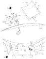
- FIG. 1 shows a typical dirt removal device (or a dirt removal device) 391 for a card.
- Fig. 1 is the outer surface (the impact circle) of the main drum indicated by the reference numeral 311, the direction of rotation of the drum is indicated by the arrow D.
- the outer surface 311 corresponds to the tips of one Set, which is not shown here, however, since it is not essential for the explanation plays and is well known by the expert.
- the device 391 comprises a first shuttering segment 421, which serves as a support for trimmed sets Carding elements 121 is formed, and a second shuttering segment 441, which as Carrier for further elements 161 provided with trimmings is formed.
- the working gap is indicated by 110, with a separation gap 180 between the segments 421, 441 remains open and opens into working gap 110.
- the separation gap is 180 covered by a hood 120 which at one end (not shown in Fig. 1) at one suitable discharge in the form of a suction is connected to through the Gap 180 to remove waste that has been discharged.
- the second segment 441 is provided with a knife 220 which one into the working gap projecting separating edge 240.
- the knife 220 is by screwing 250 (only one screw 250 visible in FIG. 1) on an end part 151 of the segment 441 attached.
- the end part 151 has a bearing surface 170 for a corresponding one Surface 119 on knife 220.
- the knife 220 can be displaced in the directions indicated by the double arrow EP are, wherein the bearing surfaces 170, 190 slide against each other. This can the position of the separating edge 240 relative to the lateral surface 311 (or that not shown Set) can be changed.
- the knife 220 also extends over the full working width, it is important that the position of the cutting edge is opposite the lateral surface 311 is set or maintained as equal as possible across the width.
- the hood 120 is pivotally mounted on the first segment 421 (holding means not shown) and prints with a rubber gasket 260 at the distance from the separation edge 240 Face of the knife 220.
- the fiber / air flow FLS is in the working gap 110 upstream from the edge 240 given by the peripheral speed and the "surface roughness" of the drum.
- the latter parameter is of course through the procurement of those not shown Garnish influenced.
- the set position of the knife 220, opposite the outer surface 311 (or in relation to the clothing carried by the lateral surface) the "immersion depth" of the separating edge 240 in the stream FLS and therefore the proportion of the incoming Fiber / air flow FLS, which "peeled" by the knife 220, into the Separation gap 180 is deflected and thereby removed from the working gap 110.
- the adjustability is important because the proportion of the processed fiber material to be eliminated depends on the template and not from the start (when constructing the Machine) can be set. This general mode of action also applies to all versions described below.
- the immersion depth of the separating edge should be selected in such a way that the "peeled" air layers have a relatively large amount of dirt particles (if need be, too Short fibers) and a few good fibers.
- the separating edge 240 set significantly closer to the lateral surface 311 than for the one opposite the drum Area 281 of segment 441 is possible - i.e. the working gap 110 spreads in the region 291 downstream of the separating edge 240 in the radial Direction from and to a degree that depends on the current setting of the knife 220 depends.
- the dissipated current component is "missing", whereby the remaining portion has to spread to the extended working gap to fill.
- zone Z of the working gap adjoining the separating edge 240 there is negative pressure, which is at most a little more air (loaded with dirt particles) pulls between the separating edge 240 and the lateral surface 311 than actually desired is.
- the spreading air flow tends to form eddies at the separating edge 240, which results in turbulence in the area 291 downstream of the separating edge 240.
- Such turbulence can cause fibers to "roll together" lead - this creates nits.
- swirls can also occur in the separation gap form themselves, which at most leads air and dirt particles back into the working gap.
- FIG. 2 shows part of an embodiment of a first variant of the invention, the one Represents improvement of the prior art of FIG. 1.
- An opening roller is included 33 indicated. It is provided with a set 120, the impact circle (or a Lateral surface) 440.
- a carrier T1 carries both a knife M1 and one Guardrail (also known as a "guardrail") LS2.
- a carrier T2 carries another Guardrail LS1, and a carrier T3 carries a second knife M2.
- Each carrier T1, T2, T3 is rotatably mounted about a respective axis of rotation D1, D2, D3.
- the carriers can be shared by a common actuator system (not shown) or each one can be rotated around the respective axis of rotation, as with the double arrows is indicated.
- Each guide rail LS has a guide surface LF and each knife M has an edge K.
- the elements shown thus form two dirt separation devices SG1, SG2, whereby each device is provided with a drain, which in this case is flexible Hood H includes.
- a drain which in this case is flexible Hood H includes.
- FIG. 2A shows only the main elements of the device SG1 (with parts of knife M1 and guardrail LS1), the description of the mode of operation but also applies to all other devices.
- the (radial) working distance (gap width) AB1 between the separating edge K and the impact circle 440 can be selected selectively. This The gap width is variable depending on the currently selected angular position of the carrier T1 about the axis of rotation D1. If e.g. the carrier T1 counterclockwise is rotated in Fig.
- the edge K dips deeper into the fiber / air stream and reduces the working distance or the gap width AB1.
- the knife M or the separating edge peels the size of this working distance K) a thick or a less thick layer of air from the working gap.
- the guide surface LF on the rail LS1 limits the spread of the flow FLS upstream of the separation gap 180.
- the effect of the guide surface LF depends essentially on the size of the working distance between the delimiting the gap 180 Nose N and the impact circle 440.
- This working distance can be divided into two Split "component", namely a component that corresponds to the above-mentioned working distance AB1 is the same and an additional component AB2.
- the peeled air amount increases the amount of dirt particles and short fibers (the Waste) too, since the outer (peeled) air layer has a relatively high percentage such substances (particles).
- the arrangement according to FIG. 2 is such that a change in the angular position of a carrier T as well as a change in the position of a knife also causes a change in the location of a guardrail in such a way that the resulting exit effects mutually support each other, i.e. they either work in the sense of an enlargement or both in the sense of one Reduction in the amount of waste.
- an adjustment movement E1 is always with an adjustment movement E4 and an adjustment movement E2 is always with one Adjustment movement E3 (by means of the common carrier T) linked.
- the changes, that arise from the adjustment of a single carrier T produce their excretion effects however not in the same device, but in successive devices, i.e.
- the carrier T1 for example, carries the knife M1 for the device SG1 but the guide rail LS2 for the device SG2.
- the carriers T1, T2, T3 etc. must therefore in the same sense to be turned around. The reasons for this arrangement can be seen from an execution of the earlier invention will be clarified, as now explained with reference to Figures 3 and 4 becomes.
- the device according to FIG. 3 is formed according to the previous invention (cf. EP-A-848 091) and it represents a further development of the device according to FIG. 1.
- a profile piece 50 e.g. made of hard anodized aluminum or steel
- the profile piece 50 also has two formwork parts 54, 56, of which one part 54 is provided with a guide surface 58, which together with the roller (not shown in Fig. 3, see impact circle 311, Fig. 1) the Working gap limited.
- the second part 56 serves as a carrier for a guide element 60 which is interchangeably attached to the support to after mounting the roller or its To face the set.
- the tapered wall part 62 between the surface 58 and the opening 52 is with a recess 64 which receives a blade blade 66. It is a fastener (Not shown) is provided so that the separating edge 240 is adjustable on the sheet 66 in the directions indicated by the double arrow EP compared to the Working gap can be positioned. The one deflected from the working gap by sheet 66 Air is replaced at the end of the baffle 58 away from the edge 240. Between the wall 68 of the profile piece 50 and the adjacent formwork element 70, an air supply opening 72 is left open, which in operation the working gap connects with the environment outside the formwork. The distance S of the opening 72 from edge 240 is preferably less than 50 mm. The opening 72 is natural in the form of a "slot" so that the opening extends all the way Working width extends. The part 70 and the profile piece 50 can be independent of one another attached to the drum shields.
- the guide surface 58 should be designed in this way and set close to the impact circle of the roller that there is no significant turbulence in the downstream working gap of the edge 240 remaining fiber / air flow arise.
- the Surface 58 advantageously be set so close to the roller that none substantial spread of current is required after edge 240. Thereby there may also be a pressure drop in the working gap at or downstream from the edge 240 largely avoided.
- the return of air from the opening 180 can be avoided become. It is also possible to more precisely determine the "peelable" portion of the fiber / air flow by adjusting the blade 66. Without this measure Under unfavorable conditions, air can circulate inside the opening 52 is generated and dirt particles back into the working gap reach.
- the inner surface 74 of the profile piece 50 becomes such designed that the discharged air enters the longitudinal channel Ka approximately tangentially and then, initially following the inner surface 74, into the area around the center of the longitudinal channel to be led.
- the removal takes place by means of suction, preferably from this central area one end AE (Fig. 4) of the channel Ka, and it is in the central area at the other end ZE air introduced into the channel Ka. This makes it possible to cover the entire working width maintain approximately constant recording conditions at the separation gap 180.
- Compressed air is preferably not used, but rather that in the working gap prevailing negative pressure is used to "substitute air" through the opening 72 move in.
- the system is therefore self-adjusting - so much air is drawn in than is necessary to avoid a substantial negative pressure. That through the separating edge generated vacuum zone is therefore by means of a suitable connecting channel connected to an air source.
- the previous invention in particular the embodiment according to FIGS. 3 and 4, enables very narrow settings of the edge 240 or the surface 58 with respect to the tips the clothing on the roller.
- the distance of the edge 240 from the clothing tips can e.g. in the range 0.25 to 0.5 mm, and the distance of the surface 58 from the clothing tips can e.g. 0.8 mm.
- An air inlet according to the previous invention is also in the execution of Fig. 2 is provided.
- T between each carrier and the respective guide rail LS provided a channel 72, both with the environment and with the Working gap is connected.
- the suspension of the rail LS on the carrier T must be designed accordingly, for which solution examples explained in the earlier application were.
- An adjustable means e.g. a slider 75 is provided in order to be able to influence the amount of air introduced via the duct 72.
- the Distance between an air-discharging edge K and the air inlet following it 72 thus depends on the dimensions of the carrier T. If this is undesirable (e.g. too large), each carrier T can be provided with air inlet channels 73 (shown with dashed lines) be provided to substitute air practically immediately after peeling off an air layer to be able to introduce K through the preceding edge.
- a device according to FIG. 3 is also possible by means of rotary movements according to the present invention to readjust the profile piece 50 with a Axis of rotation are provided, so that the adjustment of the knife 66 in the direction of the arrow EP (Fig. 2) replaced by rotating the profile 50 about the axis of rotation (or at least added).
- Such an arrangement is apparently in US-B-4,797,980 has been indicated (column 2, lines 6 to 12), although not an example of such a device was shown in the U.S. script.
- the speech apparently meant the knife and the housing are. It is not clear in US-B-4,797,980 whether or how a guide surface is set should.
- the position of the axis of rotation is in relation to the elements to be set of crucial importance. If the axis of rotation e.g. in the middle of the canal If Ka were provided (e.g. at location DA in Fig. 3), the edge would be 240 and the nose N on the guide element 60 together in the same direction of rotation (clockwise or counterclockwise) against the impact circle or away from it around the axis of rotation turned. An increase (e.g.) in the working gap width formed by the edge 240 would therefore be an increase in the working gap width formed by the nose N. accompanied. However, these two adjustment movements result in opposite technological (excretion) effects, i.e. technologically they stand out Part on.
- the axis of rotation would e.g. be provided at the location DB in FIG. 3, i.e. on a connecting line between the edge 240 and the nose N.
- This could but can only be implemented in the card with great design effort, in particular this is because the width of the separation gap 180 in the card is relatively small. It is therefore difficult to combine both essential elements of a single dirt separator to achieve a mutually supportive effect using a To adjust the axis of rotation.
- An actuator system would be possible for a device according to FIG. 3 to provide the two essential elements (the knife 66 and the guide element 60) coordinates linear shifts to the desired mutually supportive Produce effects.
- the embodiment according to FIG. 2 avoids this problem in that the knife has one device SG1 preceding in the transport direction with the guide rail LS2 of the subsequent device SG2 linked via the common, adjustable carrier T1 is.
- the distance between the knife M1 and the guide rail LS2 is so large that it is not necessary to rotate the axis of rotation D1 directly on a line between the edge of the Knife M1 and position the nose of the LS2 rail.
- the devices SG1, SG2 etc. must be adjusted in a coordinated manner in order to achieve the desired overall effect to achieve.
- the previous statements have been explained in connection with the card.
- the arrangement according to FIG. 2 could be in a so-called fixed-lid card (e.g. according to DE-Gbm-94 19 619.2) can be used.
- the invention (also in the embodiment according to FIG. 2) but is primarily intended for use in flake cleaners, as below is explained with reference to Figures 5 and 6. 5 shows a flake cleaner according to CH 1819/97 from 30.7.1997.
- FIG. 5A shows in cross section the essential elements of a new card filling chute 8 with a cleaning module, in particular the upper part of the shaft ("feed shaft”) 31, the lower part of the shaft (“reserve shaft”) 34 with conveyor rollers 35, the Material feed 32 with a feed roller 321 and a feed trough 322 and an opening roller 33.
- a fill level sensor 325 is also shown in Fig. 5A.
- the one from the The cotton wool 9 supplied to the rollers 35 is shown in FIG. 5A in a channel 36 for the not shown Feed roller of the carding machine continued.
- the side view (Fig. 5B) shows the cleaning module viewed from the same shaft in the direction of arrow R (Fig. 5A), in which Fig.
- the length of the roller 33 determines the working width B of the machine. This working width can be 1 m to 2 m, preferably 1 m to 1.5 m be.
- the feed 32 must flakes as evenly as possible over the working width B can deliver to the roller 33, and the cleaned material must be as uniform as possible be distributed over the width of the shaft part 34.
- the rollers 321, 33 are rotatable mounted in side walls (not shown) and carried by these walls.
- the axis of rotation of the roller 33 is indicated at 170. The directions of rotation are each with Arrows indicated.
- the opening roller 33 provided with a clothing works here as a transport roller, which the fiber material between the Material feed 32 and the cotton-forming device 34,35 transported.
- the "takeover point" is where the roller 33rd Fiber material takes over from the fiber beard offered by the feed, something before the highest point on the transport route.
- the fiber material is sent to three separators 104,106,108 is then passed into a deflection area 20 to arrive at the upper end of the lower shaft part 34.
- the elimination devices 104,106,108 are formed essentially the same, so that the description of the device 104 can be regarded as representative of the other two devices 106, 108 can.
- Each separating device thus comprises a respective separating element 110 and a guide element 112 preceding the separating element in the transport direction. Between the guide element 112 and the separating element 110 assigned to it there is the mouth of a separation gap 114.
- a preferred embodiment of this Aggregates in a first variant according to the present invention is as follows will be described with reference to FIG. 6. For now, however, the description of the general Arrangement completed.
- the first separation device 104 is practically “immediately” connects to the feed roller 321. Between the feed roller 321 and this the first separation device 104 there is only one guide rod 116 in the form of a traverse, which between the material captured by the opening roller 33 in the working gap the first guide element 112 and the transport roller. It is also each only a smaller distance s between a preceding device 104 or 106 and the following device 106 or 108 available.
- the front edge of the last separation element 110 is therefore in a horizontal plane E, which the Includes axis of rotation 170 of the roller 33. This "geometry" is not absolutely necessary.
- the "level E” could e.g. moved further in the direction of rotation of the roller 33 e.g. by an angle of approx. 45 ° with the horizontal plane shown form.
- any device 104,106,108 therefore preferably includes its own dirt removal system ensures that the material excreted by the respective element 110 from the Area of the transport route is removed.
- the material to be removed moves in the gap mouth and in the gap part adjoining it in one direction, the extends approximately tangentially to the roller 33. This material is preferred but redirected as soon as possible in a direction that is approximately parallel to the axis of rotation 170 extends, at least until it gets to one or the other side of the machine.
- each device 104,106, 108 is preferably with its own Drain pipe 117 provided, which is parallel to the axis 170 over the working width extends.
- the individual tubes 117 can on a machine side on a common Suction line (not shown) can be connected.
- the connection can be solved according to the principles for the card in EP-B-340 458 and EP-B-583 219 were declared. An alternative arrangement can be found in US-B-5,255,415.
- This inclination can be supported by an air flow L that is mixed with the material flow after the guide surface 22 (viewed in the transport direction) and continues to flow in said tangential direction.
- the air flow L flows past the tips 331 of the roller assembly or at most even the outer ends of these peaks through.
- the material flow is thus largely replaced by the roller 33 and in the led downward converging material deflection region 20.
- Opposing formwork 323 of the roller 33 is provided with a knock-off or stripping edge 324, which flakes protrude from the clothing can strip and deflect into the area 20.
- the casing 323 can e.g. as Hollow profile, for example by extrusion.
- the corresponding one Part closes an adjacent trough part, which has no reference number which forms the trough 322.
- the latter part can also be formed as a hollow profile become.
- the casing 323 is also provided with an inwardly projecting brush 326, with which also individual fibers remaining in the set or printed into the set Flakes are removed from the set and redirected to area 20 can before the relevant part of the garnished work surface back to the nip the feed 32 is returned.
- Brush 326 includes e.g. a support rod 327, which is received in a receiving groove in the casing 323, the Rod is provided with bristles protruding inwards.
- a brush can be easily occasionally replaced as a replaceable unit.
- the brush serves but not primarily the flake dropping, but rather the sealing of the gap between the roller 33 and the casing 323. This creates upstream of the brush 326 a back pressure, which also helps to counter the flake air flow to deflect the lower shaft part 34.
- the aforementioned air flow L flows from a calming space 24 into a box 26, of which the one wall 25 is arranged obliquely around one side of the material deflection area 20 to form.
- the opposite side of this area 20 is formed in FIG. 5A by a vertical wall part 341 that slopes upwards the formwork 323 and adjoins the bottom of a conveyor roller 35.
- the Wall part 341 is provided with an opening for receiving the level sensor 325, is not perforated and can have a seal against the casing 323.
- the air flow flowing into the shaft part 34 can therefore be on this Do not escape the shaft side.
- the wall part 341 can, however, opposite the casing 323 can be moved to the "depth" of the shaft part 34 (in a horizontal Direction perpendicular to the working width).
- the top edge of wall 25 (as viewed from axis 170) is behind you Sheet metal piece, which forms the guide surface 22.
- the axis 23 carries a wing 28, which together with the aforementioned Sheet piece forms an inflow duct for the air flow L.
- the piece of sheet metal itself is fixedly mounted opposite the roller 33, e.g. through a bent lip the top wall 27 of the box 26 is formed. By pivoting the wing 28 can but influences the width and the direction of the air flow L designed as a "curtain" or be optimized.
- the lever 231 can be operated manually or by a controlled actuator be operated.
- the air flow L is generated by a fan 29 and flows in via a flap 21 in into the calming room 24.
- the blown air could be obtained from the environment become.
- it is circulating air from the shaft part 34 obtained through holes (not specifically shown) in a wall part 342, which in the embodiment according to FIG. 5A extends vertically downward from the lower end the wall 25 extends and faces the wall part 341.
- a wall part 342 which in the embodiment according to FIG. 5A extends vertically downward from the lower end the wall 25 extends and faces the wall part 341.
- the perforated shaft wall is formed as a screen wall, the wall can be put together from parts (slats).
- the amount of air required can be determined empirically.
- the fan 29 will but preferably at a constant speed from a motor, not shown driven.
- the amount of air required can be by means of a slide 210 or the construction of the flap 21 can be adjusted.
- roller (needle roller) 33 has a diameter in the range 250 up to 300 mm
- a fine cleaner should have an opening roller with a diameter larger than 350 mm, e.g. 400 mm.
- the working width can be in Range 1 to 1.5 m, e.g. 1.2 m.
- Fig. 6 shows the preferred embodiment of a first variant of the fiber cleaning unit for a cleaning module according to FIG. 5.
- Each device 104, 106, 108 comprises in this version a profile 600 which e.g. can be formed as a continuous casting profile.
- the direction of transport (flow direction of the fiber / air flow FLS) is with an arrow indicated.
- Each profile 600 has a cavity 602, which forms the discharge channel, and has two approaches 606 and 608, respectively.
- the approach 606 forms a mounting surface for Working element 610, which is described in more detail below.
- the approach 608 forms one side of a guide channel 612 which opens into the discharge channel 602.
- the element 610 is firmly attached to shoulder 606 by means of screws.
- Each working element 610 is in the form of an elongated rod with one over it Length uniform, essentially triangular cross-section formed.
- the element 610 has a separating edge at the front end (viewed in the direction of transport) 616, at the rear end a nose 618 and an intermediate guide surface 620, which is opposite in operation of the roller (not shown).
- the working elements 610 are arranged side by side in such a way that they are essentially continuous Form casing for the roller, with a separation gap 622 between each neighboring elements is formed. Each gap 622 opens into a respective one Channel 612.
- the fiber cleaning unit according to FIG. 6 therefore differs from the unit in that respect 5 as the individual separation and guide elements 110 and 112 5 have been combined in a single working element 610 according to FIG. 6.
- the guide surface 620 and the nose 618 for the device 106 are accordingly corresponding 6 worn in the device 104 or integrated therein.
- the profiles 600 are mounted in the frame by means of rotary bearings (see FIG. 5B) and are therefore each rotatable about its own axis of rotation 105, 107, 109 (see FIG. 5A).
- the arrangement is similar that of Figure 2 in that e.g. axis of rotation 105 between edge 616 of the device 104 and the nose 618 of the device 106 is provided.
- the axis of rotation 107 is between the edge 616 of the device 106 and the nose 618 of the device 108 intended.
- a plane EB which is both the axis of rotation of the needle roller and one of the axes of rotation 105, 107, 109, the corresponding contact surface 620 cuts into two Parts. These parts can be of approximately the same length, which means that one Swiveling movement of a profile 600 same adjustment movements of the corresponding Edge 616 and nose 618 cause, that is, the change in the immersion depth of the Edge 616 corresponds approximately to the change in the working gap width defined by the nose. If one of the two adjustment movements should be larger than the other, the position of the corresponding profile rotation axis can be shifted so that the level EB newly divides the guide surface 620 into unequal parts.
- Devices 104, 106, 108 can all share a common lever mechanism Actuator connected, this actuator for manual operation or can be provided for motor actuation.
- the coordinated setting all devices are therefore guaranteed by the lever mechanism.
- the same effect could of course be achieved by means of a programmable controller, if the devices are not mechanically connected to each other.
- the arrangement can be followed in a so-called VARIO set system Integrate EP-A-452 676.
- the speed of the needle roller be selected selectively to adjust the intensity of the fiber processing, with a higher intensity a cleaning improvement but also an increased risk of fiber impairment (fiber shortening).
- the settings of the Working elements 610 can be selectively selected to allow waste disposal influence, a greater immersion depth of the edges K an increased amount of waste with an increased risk of loss of guff fiber.
- a baffle (not shown - see but element 116, Fig. 5A) provided to transfer the fibrous material between to ensure the feed roller 321 and the first separating edge.
- the contact surface upstream of the first separating edge is preferably fixed, but could can be variably set in the same way as the other guiding surfaces.
- the baffle 620 downstream from the last separating edge 616 is set together with this edge, which does nothing in and of itself, since this guide surface has no other separating edge is followed.
- the variable setting of the last guide surface has no disadvantages with and it enables the uniform design of the devices 104, 106, 108, which of logistics or assembly is advantageous.
- FIG. 7 and 8 each show two adjacent grate bar modules M1 of a grate device for one Flake cleaner (fine cleaner) according to EP-A-481 302.
- the impact circle of a clothing on a rotatable roller is shown in simplified form in FIG. 7 and 8 as a straight line 440.
- the grate modules M1 can be pivoted together about respective pivot axes 33 e.g. by the clearance angle from the value ⁇ 1 (FIG. 7) to the value ⁇ 2 (FIG. 8) increase, or vice versa.
- the position of the pivot shaft 33 in the area of the left corner of each grate bar module shown has the consequence that when the grate bar module is pivoted about the axis of rotation the pivot shaft 33, the distance B (i.e., the distance in the radial direction between the leading edge 77 of each module M1 and the trailing edge 75 of the previous one Module) e.g. is expanded from B1 to B2 (see FIG. 8), while on the other hand the distance A2 (between each leading edge 77 and the beating circle 440 in Fig. 8) is not essential is greater than the corresponding distance Al in Fig. 7, i.e. through the adjustment of module M1 is practically unchanged.
- the distance A1 set once is therefore only negligibly changed by the mentioned swiveling when re-setting the angle ⁇ (or ⁇ ).
- the second variant of the present invention is based on the latter new knowledge and develops it further.
- Line Q represents one "Reference surface", which is shown here as a plane for the sake of simplicity, in practice but can have a curvature (lateral surface of a rotatable roller, cf. Just 440 in Figures 7 and 8).
- the fully drawn AF line represents an excretion area (similar to the guide surface 74 in Figures 7 and 8), where on at its front end (near the reference surface) Edge K.
- the separating surface carries air deflected by the edge K. the working gap.
- the solid line LF represents a guide surface.
- the reference symbol Q1 indicates an imaginary plane that is parallel to the reference surface Q stands and intersects the edge K.
- the direction of transport of the fiber / air flow is indicated by the arrow FLS, from where it can be seen that the material flow first flows over the guide surface LF and then strikes the edge K. There is between the contact surface LF and the edge K. a separation gap AS. Part of the current is peeled off by the edge K and derived through the gap AS.
- the contact surface LF and the separation surface AF are adjustable to influence the excretion effect. Appropriate means of adjustment of these areas will be explained below, but play for the explanation the principles don't matter.
- One setting option is to compare the angular position of the separating surface AF to change the reference area Q (Q1) or with respect to the fiber / air flow, e.g. by shifting the area AF into that indicated by the dashed line Digit (corresponds to an increase in the "setting angle" "from ⁇ 1 to ⁇ 2).
- the position of the edge K remains essentially unchanged.
- FIG. 9A Another setting option is to direct the guide surface LF in the direction of the To shift the reference surface Q that the width of the gap FS adjacent to the separation gap AS is reduced.
- This can e.g. by moving the guide surface into the location indicated by the broken line (Fig. 9A), i.e. without one Changing the angular position of the guide surface LF.
- the required effect could be but can be achieved by pivoting the guide surface LF around its front edge VK becomes.
- the excretion effect becomes also reduced.
- Figures 9D and 9E By reversing these adjustment movements, the excretion effect of course, vice versa.
- Fig. Fig. 9D shows the arrangement with a very wide gap FS and Fig. 3E with a very narrow gap, with all other features of the arrangement (especially the angular position the area AF) remain unchanged compared to FIG. 9D.
- the setting angle ⁇ can advantageously be between 20 ° and 40 °, preferably between 25 ° and 35 ° adjustable.
- the distance FS can advantageously be between 0.5 mm and 10 mm, preferably be adjustable between 1 and 5 mm, with "reference surface" Q for the determination of the distance FS of the impact circle (the lateral surface) of the Transport roller worn set applies.
- FIGS. 10 and 11 Based on FIGS. 10 and 11, exemplary embodiments for realizing the The principles according to FIG. 9 are explained in a module according to FIGS. 5A and 5B.
- 10A shows the feed roller 321, the guide rod 116 and the first separating device 104 with its guide element 112, separating element 110 and separating gap 114, and the impact circle 440 (the outer surface) of the roller 33.
- the two elements 110, 112 are fixedly attached to the housing 117 of the discharge duct, or from a Pieces formed (e.g. as parts of a continuous casting profile).
- the housing 117 is provided with an extension piece 118, which is received in a respective pivot bearing 119.
- the pivot bearing 119 are mounted in the side walls (not shown) of the machine about an axis of rotation DA (see also FIG. 10A) for the excretion device 104.
- the (in Fig. 10B) left extension piece 118 is connected to an adjusting lever 120, which is manual or by means of a controlled actuator system (indicated schematically by the box Ak) can be operated to perform an adjustment.
- housing 117 When housing 117 is rotated clockwise (as shown in Fig. 10A), move the elements 110, 112, e.g. from those indicated with solid lines Positions in the positions indicated by dashed lines.
- FIG. 10C where the designations AF, LF (see FIG. 9) used again for the aforementioned separating and guiding surfaces were.
- FIG. 11 shows two shuttering segments 200, 202 for a roller 204 of an opening and cleaning machine in the blow room or carding machine, e.g. a fine cleaner or Runaway.
- the reference symbol AS again indicates an elimination gap.
- the reference symbol F1 indicates a first wing, which is the guide surface LF for this Variant.
- the wing F is rotatable on the segment 200 about an axis of rotation 206 mounted.
- the reference symbol F2 indicates a second wing which has the edge K.
- the Wing F2 is mounted on segment 202 so as to be rotatable about an axis of rotation 208 this axis 208 practically coincides with the edge K.
- the two axes of rotation 206, 208 can be connected to a common actuator system (schematically Ak), whereby the transmission of motion from the actuator system Ak to the axes of rotation 206, 208 ′ in such a way can be designed that a movement of a motor in the actuator Ak in different Movements of the wings F1, F2 (according to Fig. 11) is translated.
- FIG. 12 shows a further cleaning module, both according to the present one as was designed according to the previous invention (EP-A-848 091).
- This figure shows (as FIG. 5A) a feed roller 321 only partially shown followed (in the Direction of transport) by a traverse 116, and the impact circle 440 of a transport or opening roller (not specifically indicated).
- a traverse 116 follows after traverse 116 three dirt separating devices 304, 306, 308, the device 304 only partially depicted is. Since these devices are essentially identical, a description is used of the device 306 also for the other two.
- Each device includes one tubular housing 317, a separating element 310, and a nose 312, wherein a Separation gap 314 is present between the nose 312 and the element 310.
- the Nose 312 and element 310 are either attached to housing 317 or so formed from one piece, and the whole is rotatably mounted about an axis of rotation DA (not shown, see Fig. 10B).
- the element 310 is provided with an edge K and carries also an axis of rotation 305 for a guide wing 307, which is similar to wing F1 (FIG. 11) is formed.
- the wing 307 partially covers an air intake duct 309 between the Nose 312 and the separating element of the preceding one (in the flow direction) Device.
- Channel 309 is connected to the "environment" of the machine for air to escape to be able to insert it into the working or transport gap. It is a similar one Channel 309A between the cross member 116 and the first device 304 and another Channel 309B is provided downstream of the last device 308.
- the vanes 307 direct the air flows from the channels 309, 309B into each of the Direction of transport around.
- the wing 307 of the device 304 mainly serves as Guide element for the device 306, and the wing 307 of the device 306 serves as a guide element for the device 308. Since the latter function already with reference to FIG. 11 (for the Wing F1) has been explained, repetition is omitted here.
- the setting angle of the separating element 310 by rotating the housing 317 about the axis of rotation DA, during the distance between the free end of wing 307 and the stroke circle 440 can be adjusted separately by rotating the wing about the axis of rotation 305 got to.
- the setting angle ⁇ (see FIG. 9A) is in this case between an imaginary Extension of the separation surface of element 310 and a tangent on Impact circle 440 is shown where the impact circle is cut through the aforementioned extension becomes.
- the guide rod (traverse) 116 which are provided in front of the first device 304 must not be provided with a Leifinatel, since this rod itself as a guide for the first device 304 is used.
- the angular position of the guide rod can be adjusted accordingly to get voted.
- the feed roller 321 or the feed trough assigned to the roller may be movably supported to interpose itself to adjust the clamped amount of fiber.
- the preferred embodiment of the second variant comprises for each separation device 104, 106, 108 (see FIG. 5) a profile 500 with a cavity 502, which the Suction channel forms.
- the profiles can each be rotated about their own longitudinal axis 105, 107, 109 (see Fig. 5A).
- the profile 500 of the device 108 has a longitudinal slot 504, which opens into the cavity 502 and forms the discharge slot 114 (see FIG. 5).
- the shoe 508 is one against Direction of rotation of the roller 33 provided facing attachment 512, of which the front end forms a separating edge.
- the shoe 508 with its attachment 512 together with the separating edge forms the separating element 110 (cf. FIG. 5) with a separating surface 513.
- the others Profiles 500 are identically formed and each provided with a shoe, the reference numerals have been omitted for clarity of presentation improve.
- the slot 504 On the other side of the slot 504 there is a longitudinal part 514 with one against the surface 516 facing the transport roller.
- the part 514 forms the guide element 112 (see FIG. 5A) and the surface 516 forms the contact surface for the one moving with the roller 33 Fiber / air flow.
- the three devices in Fig. 13 are shown in three different settings, which is usually will not occur but is useful for illustration.
- the device 106 is located in a medium (basic) setting, in which the separating edge is in one plane (the "base plane") GB, which is also the axis of rotation 107 of the device 106 and includes the axis of rotation 170 of the roller 33 (see FIG. 5A).
- the device 104 is located in such a setting that the separating edge of this device against the direction of rotation P of the roller 33 has been shifted beyond the plane GE (“forwards”), which corresponds to a reduction in the angle ⁇ (Fig. 9). This results in a relative high excretion effect compared to the basic position shown in device 106.
- connection level which connects the axis of rotation 109 with the separating edge
- Base plane GE viewed in the direction of rotation P
- Fig. 13 now shows that the change shown in the angular position of the separation surface 513 by pivoting the profile through the angles ⁇ on both sides of the basic position can be achieved, with the working gap between the separating edge and the roller 33, not shown, hardly changes.
Abstract
Description
Die Erfindung befasst sich mit Schmutzausscheidevorrichtungen (Schmutzausscheidegeräten) zur Verwendung in Faserreinigungsaggregate einer Spinnerei sowie entsprechenden Aggregaten.The invention is concerned with dirt separation devices (Dirt separators) for use in fiber cleaning units Spinning mill and corresponding aggregates.
Grundsätzlich ist es bekannt, Schmutzausscheidevorrichtungen mit "Messern" sowohl an der Karde wie auch in (Flocken-) Reinigungsmaschinen vorzusehen. In einem konventionellen Flockenreiniger wird die Vorlage normalerweise in der Form einer Watte geliefert und das gereinigte Material wird (pneumatisch) als Flocken an die nächste Maschine in der Putzereilinie weitergeleitet. In der Karde arbeitet die Ausscheidevorrichtung an Fasermaterial in der Form eines Vlieses, wobei der Öffnungsgrad des Fasermaterials in diesem Vlies viel höher als der Öffnungsgrad der Fasern in Flocken ist. Im Flockenreiniger hat das Material noch einen lockeren Zusammenhalt, der in der Karde verschwunden (oder zumindest viel niedriger) ist.Basically, it is known to have dirt separators with "knives" both to be provided on the card as well as in (flake) cleaning machines. In a conventional one Flake cleaner is usually the template in the form of a cotton ball delivered and the cleaned material is (pneumatically) as flakes to the next Machine forwarded in the blowroom line. The separation device works in the card of fiber material in the form of a fleece, the degree of opening of the fiber material in this fleece is much higher than the degree of opening of the fibers in flakes. In the flake cleaner, the material still has a loose cohesion, which in the Card has disappeared (or at least much lower).
Diese Erfindung befasst sich sowohl mit Schmutzausscheidevorrichtungen bzw. Faserreinigungsaggregaten
für die Flockenreinigung, wo das zu reinigende Material noch
nicht bis zu Einzelfasern geöffnet worden ist, als auch für die Karde, wo das Material in
der Form eines Vlieses vorliegt, das aus bis zu Einzelfasern geöffneten Fasern besteht.
Die Erfindung ist speziell zur Verwendung in einem neuen Reinigungsmodul nach
EP-A-810 309 konzipiert, wobei sich dieses Modul in einem Kardenfüllschacht befindet.
Die Erfindung könnte aber auch in einem (sonst) konventionellen Flockenreiniger oder
in der Karde angewendet werden.This invention is concerned with both dirt removal devices and fiber cleaning units
for flake cleaning, where the material to be cleaned still
has not been opened up to individual fibers, as well as for the card where the material in
is in the form of a fleece, which consists of fibers opened up to individual fibers.
The invention is specifically for use in a new cleaning module
EP-
Eine typische konventionelle Schmutzausscheidevorrichtung für die Karde wird nachfolgend anhand der Fig. 1 erklärt werden, weshalb auf eine Erläuterung des Standes der Technik an dieser Stelle verzichtet wird. A typical conventional carding machine for dirt removal is shown below will be explained with reference to Fig. 1, why an explanation of the status the technology is dispensed with here.
Flockenreiniger mit einstellbaren Ausscheideelementen sind in den folgenden Schriften gezeigt:Flake cleaners with adjustable separating elements are in the following documents shown:
DE-A-27 12 650 (Schubert & Salzer) - schlägt einen Reiniger mit mehreren Walzen vor, wovon jede Walze mit einem eine Abscheideöffnung aufweisenden Gehäuse versehen ist. Jede Abscheideöffnung ist einer Abscheidekante zugeordnet und die Abscheidekanten sind einstellbar an Gehäuseteilen befestigt. Über die Art und Weise der Einstellung wird in DE-A-27 12 650 nichts gesagt.DE-A-27 12 650 (Schubert & Salzer) - proposes a cleaner with several rollers, of which each roller is provided with a housing having a separation opening is. Each separation opening is assigned to a separation edge and the separation edges are adjustable attached to housing parts. About the way of hiring nothing is said in DE-A-27 12 650.
EP-A-481 302 (Rieter) - befasst sich mit einer einstellbaren Rostanordnung. Die Figuren 5 und 6 und die entsprechende Beschreibung zeigen detailliert das Einstellen gewisser Rostelemente. Diese Figuren sind auch in der vorliegenden Anmeldung aufgeführt, weshalb auf eine genauere Erklärung an dieser Stelle verzichtet werden kann.EP-A-481 302 (Rieter) - deals with an adjustable grate arrangement. The figures 5 and 6 and the corresponding description show the setting of certain ones in detail Rust elements. These figures are also listed in the present application, which is why a more detailed explanation can be omitted here.
EP-A-459 569 (Marzoli) - wonach ein im wesentlichen konventionelles Reinigungsgerät mit Abscheidemessern vorgesehen ist, wobei kurz vor dem Materialausgang die Messer mit einer einstellbaren Trennfläche ergänzt werden.EP-A-459 569 (Marzoli) - after which an essentially conventional cleaning device is provided with separation knives, the knives shortly before the material exit can be supplemented with an adjustable dividing surface.
US-B-5,031,279 (Trützschler) - wonach viele individuell einstellbare Elemente auf einem gemeinsamen Träger vorgesehen sind. Die Messer sollen gänzlich in ungefähr radialen Richtungen gegenüber einer Walze eingestellt werden.US-B-5,031,279 (Trützschler) - according to which many individually adjustable elements on one common carriers are provided. The knives are said to be roughly complete radial directions can be set with respect to a roller.
US-B-4,805,268 (Trützschler) - wonach eine motorisch angetriebene Aktorik für verschiedene einstellbare Elemente vorgesehen ist. In diesem Fall ist sowohl das radiale Einstellen eines Messers als Ganzes wie auch das Schwenken um eine Achse vorgesehen, die mit der Messerkante zusammenfällt. In einer weiteren Ausführung ist ein Leitelement einstellbar, die Ausscheidemesser aber fix angeordnet. Absaugungen sind in dieser Schrift erwähnt, es sind aber keine in den zutreffenden Figuren (Fig. 3 und Fig. 6) gezeigt. US-B-4,805,268 (Trützschler) - according to which a motor-driven actuator system for various adjustable elements is provided. In this case it is both radial Adjustment of a knife as a whole as well as swiveling around an axis are provided, that coincides with the knife edge. In another version is a Guide element adjustable, but the knives are fixed. Suction are mentioned in this document, but there are none in the relevant figures (FIGS. 3 and Fig. 6) shown.
Im Stand der Technik ist oft die Rede von "Messern" (auch "Klingen" genannt), wobei ein "Messer" normalerweise ein Blatt aufweist, das gegenüber einer sich drehenden Walze einstellbar ist. Es ist aber auch bekannt, eine ähnliche Funktion durch eine Kante (auch "Trenn-" oder "Ausscheidekante" genannt) auszuüben, wobei diese Kante an einem Element gebildet ist, das nicht unbedingt als einstellbarer "Messer" konzipiert ist, z.B. an einem "Roststab". Die Erfindung ist ebenfalls in solchen Anordnungen anwendbar. Um schwerfällige Wiederholungen in der Beschreibung zu vermeiden, wird nachfolgend von einem Ausscheideelement mit einer Kante gesprochen, wobei dieser Begriff die Spezialformen "Stab", "Messer" bzw. "Klinge" sowie "Blatt" umfasst.In the prior art there is often talk of "knives" (also called "blades"), whereby a "knife" usually has a blade that faces a rotating one Roller is adjustable. But it is also known to perform a similar function through a Edge (also called "separating" or "excretion edge"), this edge is formed on an element that is not necessarily designed as an adjustable "knife" is, e.g. on a "grate bar". The invention is also applicable in such arrangements. In order to avoid cumbersome repetitions in the description, subsequently spoken of a separating element with an edge, this Term includes the special forms "stick", "knife" or "blade" and "blade".
Bekannt ist eine faserverarbeitende Maschine mit einer drehbaren Walze, wobei ein Faser/Luft-Strom in einem "Arbeitsspalt" zwischen dem Umfang der Walze und einer ihn umgebenden Verschalung fliesst. Ein Ausscheideelement ist in der Verschalung vorgesehen. Die Selektivität der Ausscheidung wird dadurch erzielt, dass die Walze mit einer faserhaltenden Garnitur versehen ist, während die Fliehkraft Schmutzpartikel, die allenfalls schwerer als die Fasern sind bzw. einen höheren Strömungswiderstand als die Fasern aufweisen, radial nach aussen (gegen die Verschalung) drängt, wo sie mittels dem Ausscheideelement aus dem Strom abgelenkt werden können. Der Arbeitsspalt erstreckt sich normalerweise über fast die ganze axiale Länge (über die "Arbeitsbreite") der Walze.A fiber processing machine with a rotatable roller is known, wherein a Fiber / air flow in a "working gap" between the circumference of the roller and one the surrounding formwork flows. A separation element is in the formwork intended. The selectivity of the separation is achieved in that the roller with a fiber-containing set is provided, while the centrifugal dirt particles possibly heavier than the fibers or a higher flow resistance than the fibers have to push radially outwards (against the formwork), where they by means of the separating element can be deflected from the stream. The working gap usually extends over almost the entire axial length (over the "Working width") of the roller.
Zumindest aus EP-A-481 302 und US-B-4,805,268 ist es in einer derartigen Maschine bekannt, die Winkelstellung eines Ausscheideelementes gegenüber dem Materialstrom einzustellen, um die Ausscheidewirkung zu beeinflussen. Zumindest aus US-B-5,031,279 und US-B-4,805,268 ist es bekannt, ein dem Ausscheideelement in der Transportrichtung vorgeschalteten Leitelement einzustellen, um die Ausscheidewirkung zu beeinflussen. At least from EP-A-481 302 and US-B-4,805,268 it is in such a machine known, the angular position of a separating element relative to the material flow adjust to influence the excretion effect. At least from US-B-5,031,279 and US-B-4,805,268 it is known to use a separating element in the Direction of transport upstream guide element to adjust the separation effect to influence.
Die frühere Erfindung, bzw. die frühere Anmeldung:The earlier invention or the earlier application:
Die nun vorliegende Erfindung kann mit der Erfindung (die "frühere Erfindung") nach EP-A-848 091 (die "frühere Anmeldung") kombiniert werden.The present invention can be done with the invention (the "previous invention") EP-A-848 091 (the "previous application") can be combined.
Die Aufgabe der früheren Erfindung besteht darin, den Lufthaushalt stromabwärts von einem mit einer Absaugung versehenen Ausscheideelement zu verbessern. Dadurch kann die von Luftturbulenzen verursachte Nissenbildung in einer faserverarbeitenden Maschine reduziert werden. Es kann aber auch eine Verbesserung der Schmutzausscheidung an und für sich erzielt werden.The object of the previous invention is to keep the air balance downstream to improve a separation element provided with a suction. Thereby The formation of nits caused by air turbulence in a fiber processing plant Machine can be reduced. But it can also improve dirt removal be achieved in and of itself.
Die frühere Erfindung sieht daher eine faserverarbeitende Maschine mit einem Ausscheideelement vor, wobei sowohl Faser wie auch Luft in einer im wesentlichen vorbestimmten Transportrichtung am Element vorbeigeführt werden und Schmutzpartikel selektiv mittels des Elementes aus dem Faser/Luft-Strom abgeführt werden soll. Die Erfindung ist dadurch gekennzeichnet, dass mindestens eine Massnahme getroffen ist, um die Luftströmungen in der Zone stromabwärts vom Element zu beeinflussen. Die gesagte Massnahme kann derart getroffen werden, dass Luftturbulenzen stromabwärts (in der Transportrichtung) vom Element begrenzt oder sogar (möglichst) eliminiert werden.The previous invention therefore sees a fiber processing machine with a separating element before, with both fiber and air in a substantially predetermined Direction of transport past the element and dirt particles to be removed selectively from the fiber / air stream by means of the element. The Invention is characterized in that at least one measure is taken to affect the air flow in the zone downstream of the element. The said measure can be taken such that air turbulence downstream limited (in the direction of transport) by the element or even eliminated (if possible).
Die Massnahme besteht vorzugsweise darin, dass durch das Element abgeführte Luft zumindest teilweise durch neueingeführte Luft ersetzt wird. Die neueingeführte Luft fliesst zweckmässigerweise in die am Element anschliessende Zone hinein, z.B. innerhalb eines Abstands von ca. 50 mm stromabwärts vom Element und vorzugsweise innerhalb eines Abstands von weniger als 20 mm.The measure preferably consists in the air being discharged through the element is at least partially replaced by newly introduced air. The newly introduced air expediently flows into the zone adjoining the element, e.g. within a distance of about 50 mm downstream of the element and preferably within a distance of less than 20 mm.
Vorzugsweise ist die Anordnung bezüglich der einfliessenden Luftmenge selbsteinstellend, d.h. (z.B.), dass nicht mit Blasluft gearbeitet werden muss. Wenn der freie Strömungsquerschnitt vom Lufteinfuhrkanal ausreichend dimensioniert ist, entsteht die erforderliche Luftströmung wegen eines Unterdruckes im Raum stromabwärts vom Element.The arrangement is preferably self-adjusting with respect to the inflowing amount of air, i.e. (e.g.) that there is no need to work with blown air. If the free flow cross section is adequately dimensioned by the air intake duct, the necessary is created Air flow due to negative pressure in the room downstream of the element.
Die nun vorliegende Erfindung kann mit Vorteil in einem Modul nach der schweizerischen Patentanmeldung Nr. CH 1819/97 vom 30 Juli 1997 verwendet werden. Ein solches Modul umfasst eine Transportwalze für einen Faser-/Luft-Strom und eine Mehrzahl von Schmutzausscheidegeräten dem Umfang der Walze entlang verteilt, wobei jedes Gerät ein Ausscheideelement, einen Ausscheidespalt und eine dem Spalt zugeordnete Schmutzabfuhr umfasst.The present invention can advantageously in a module according to the Swiss Patent application no. CH 1819/97 dated July 30, 1997 can be used. Such one Module comprises a transport roller for a fiber / air stream and a plurality of dirt separators distributed along the circumference of the roller, where each device has a separating element, a separating gap and one assigned to the gap Dirt removal includes.
Die nun vorliegende Erfindung befasst sich mit Schmutzausscheidegeräten und mit daraus gebildeten Faserreinigungsaggregaten. Es ist die Aufgabe der Erfindung, die Wirksamkeit der bekannten Anordnungen zu verbessern.The present invention is concerned with dirt separators and with fiber cleaning units formed therefrom. It is the object of the invention that To improve the effectiveness of the known arrangements.
Die Erfindung sieht ein Schmutzausscheidegerät vor, das zum Anbringen an einem Faser-/Luft-Strom vorgesehen ist. Das Gerät umfasst ein Ausscheideelement, das in selektiv wählbaren Stellungen gegenüber dem Strom eingestellt und gehalten werden kann sowie eine Schmutzabfuhr für durch das Ausscheideelement aus dem Strom abgelenktes Material. Das Gerät umfasst auch ein Leitelement, das einem Ausscheideelement in der Transportrichtung vorgeschaltet werden kann, wobei die Stelle des Leitelementes quer zur Transportrichtung einstellbar ist, um die entsprechende Arbeitsspaltbreite zu verändern. Die Anordnung ist derart getroffen, dass Einstellbewegungen des Ausscheideelementes von vorgegebenen Bewegungen des Leitelementes begleitet werden. The invention provides a dirt separator that can be attached to a Fiber / air flow is provided. The device includes a separating element, which in selectively selectable positions relative to the current can be set and held can as well as a dirt removal for what is deflected from the stream by the separating element Material. The device also includes a guide element, which is a separating element can be connected upstream in the transport direction, the location of the guide element is adjustable transversely to the direction of transport to the corresponding working gap width to change. The arrangement is such that adjustment movements of the Ausscheideelementes accompanied by predetermined movements of the guide element become.
Das Gerät kann derart angeordnet werden, dass durch einen Einstellvorgang das Leitelement den Arbeitsspalt verengen und das Ausscheideelement gedreht werden kann, um eine Teilstrom ablenkende Fläche näher an eine gedachte, im wesentlichen radiale Ebene zu bewegen. Der umgekehrte Einstellvorgang sollte natürlich auch möglich sein. Einstellmittel für das Ausscheideelement und für das Leitelement können derart verknüpft bzw. vereinigt werden, dass eine bestimmte Einstellbewegung des Ausscheideelementes (Leitelementes) durch eine entsprechende Bewegung des Leitelementes (Ausscheideelementes) begleitet wird. Eine mechanische Verbindung ist aber nicht unbedingt erforderlich, da die erwünschte Wirkung allenfalls durch das Vorsehen einer geeigneten Steuerung für die Einstellaktorik erzielt werden kann, wobei dann für die beiden Elemente je ein steuerbarer Antrieb vorgesehen werden kann. Es kann auf jeden Fall dafür gesorgt werden, dass eine Änderung der Stellung des Ausscheideelementes, welche eine bestimmte technologische (Ausscheide-) Wirkung herbeiführt, durch eine Änderung der Stelle des Leitelementes begleitet wird, welche die gesagte Wirkung unterstützt.The device can be arranged such that the guide element by an adjustment process narrow the working gap and the cutting element can be rotated, around a partial flow deflecting surface closer to an imaginary, essentially radial Level. The reverse setting process should of course also be possible. Setting means for the separating element and for the guide element can be linked in this way or be united that a certain adjustment movement of the separating element (Guide element) by a corresponding movement of the guide element (Separation element) is accompanied. However, a mechanical connection is not essential required, since the desired effect is at best provided by a suitable control for the setting actuators can be achieved, then for the A controllable drive can be provided for each of the two elements. It can affect everyone Case be made sure that a change in the position of the separating element, which brings about a certain technological (elimination) effect, is accompanied by a change in the position of the guide element, which the said Effect supports.
"Begleitung" bedeutet daher hier nicht (unbedingt) Gleichzeitigkeit. Die Bewegungen der Elemente können sequentiell erfolgen, wobei die Sequenz vorprogrammiert ist."Accompaniment" therefore does not necessarily mean simultaneity. The movements of the elements can take place sequentially, the sequence being preprogrammed.
Das Ausscheideelement und das Leitelement können beide in einem einzigen Schmutzausscheidegerät vorgesehen werden, welches einer Schmutzabfuhr zugeordnet ist.The separating element and the guide element can both be in one Dirt removal device can be provided, which is assigned to a dirt removal is.
Das Ausscheideelement kann derart angeordnet werden, dass seine Eintauchtiefe in den Faser-/Luft-Strom einstellbar ist. In der bevorzugten Anordnung mit variabler Eintauchtiefe umfasst ein Faserreinigungsaggregat mehrere Schmutzausscheidegeräte, wobei das genannte Ausscheideelement in einem Gerät und das vorgeschaltete Leitelement in einem weiteren Gerät vorgesehen sind. Die bevorzugte Anordnung ist insbesondere zur Verwendung in einem Flockenreiniger konzipiert, könnte aber auch z.B. in einer Festdeckelkarde verwendet werden. The separating element can be arranged such that its immersion depth in the fiber / air flow is adjustable. In the preferred arrangement with variable immersion depth a fiber cleaning unit includes several dirt separators, said separation element in one device and the upstream guide element are provided in another device. The preferred arrangement is particular designed for use in a flake cleaner, but could also e.g. in a fixed lid card can be used.
Ausführungen der Erfindung werden nachfolgend anhand der schematischen Zeichnungen als Beispiele beschrieben.Embodiments of the invention are described below using the schematic drawings described as examples.
Es zeigt:
- Fig. 1
- einen Schnitt durch eine bekannte Vorrichtung zur Verwendung in einer Karde,
- Fig. 2
- eine schematische Darstellung einer ersten Ausführung nach einer ersten Variante der Erfindung, wobei Fig. 2A die wesentlichen Beziehungen zu einem grösseren Massstab zeigt,
- Fig. 3
- einen Schnitt durch eine Anordnung nach der früheren Erfindung (EP-A-848 091),
- Fig. 4
- eine schematische isometrische Darstellung der bevorzugten Absaugung in einem Gerät nach Fig. 3,
- Fig.5A und
- Kopien der Fig. 3A und 3B aus unserer schweizerischen Patentanmeldung
- Fig.5B
- Nr. 1819/97 vom 30 Juli 97 und
- Fig. 6
- eine bevorzugte Ausführung der ersten Variante der Erfindung zur Verwendung in einem Reinigungsmodul nach Fig. 5,
- Fig. 7 und 8
- Kopien der schon erwähnten Figuren 5 und 6 aus EP-A-481 302,
- Fig.9A
- ein Diagramm zur Erklärung der neueren Einstellungsprinzipien in einer zweiten Variante, wobei die Figuren 9B, C, D und E schematisch die Strömungsverhältnisse bei verschiedenen Einstellungen in der Anordnung nach Fig. 9A darstellen,
- Fig.10A und 10B
- Ein Ausscheidegerät nach der zweiten Variante für das Reinigungsmodul nach Fig. 5, zu einem grösseren Massstab abgebildet, und die Fig. 10C ein Detail aus Fig. 10A zu einem noch grösseren Massstab,
- Fig. 11
- eine schematische Darstellung einer Alternativanordnung zur Verwendung in der Putzerei (in einen Feinreiniger),
- Fig. 12
- eine Weiterentwicklung der zweiten Variante der vorliegenden Erfindung durch Kombination mit der früheren Erfindung, und
- Fig. 13
- eine weitere Ausführung der zweiten Variante.
- Fig. 1
- 2 shows a section through a known device for use in a card,
- Fig. 2
- 1 shows a schematic illustration of a first embodiment according to a first variant of the invention, FIG. 2A showing the essential relationships on a larger scale,
- Fig. 3
- a section through an arrangement according to the previous invention (EP-A-848 091),
- Fig. 4
- 3 shows a schematic isometric illustration of the preferred suction in a device according to FIG. 3,
- Fig.5A and
- Copies of Figures 3A and 3B from our Swiss patent application
- Fig. 5B
- No. 1819/97 dated July 30, 97 and
- Fig. 6
- 2 shows a preferred embodiment of the first variant of the invention for use in a cleaning module according to FIG. 5,
- 7 and 8
- Copies of the already mentioned FIGS. 5 and 6 from EP-A-481 302,
- Fig.9A
- FIG. 9B, C, D and E schematically represent the flow conditions at different settings in the arrangement according to FIG. 9A,
- Figures 10A and 10B
- A separation device according to the second variant for the cleaning module according to FIG. 5, shown on a larger scale, and FIG. 10C shows a detail from FIG. 10A on an even larger scale,
- Fig. 11
- a schematic representation of an alternative arrangement for use in the blow room (in a fine cleaner),
- Fig. 12
- a further development of the second variant of the present invention by combination with the previous invention, and
- Fig. 13
- another version of the second variant.
Fig. 1 zeigt eine typische Schmutzausscheidevorrichtung (bzw. ein Schmutzausscheidegerät)
391 für eine Karde. In Fig. 1 ist die Mantelfläche (der Schlagkreis) der Haupttrommel
mit dem Bezugszeichen 311 angedeutet, wobei die Drehrichtung der Tromrnel
mit dem Pfeil D angegeben ist. Die Mantelfläche 311 entspricht den Spitzen einer
Garnitur, die aber hier nicht gezeigt ist, da sie für die Erklärung keine wesentliche Rolle
spielt und vom Fachmann wohl bekannt ist. Die Vorrichtung 391 umfasst nach Fig. 1
ein erstes Verschalungssegment 421, das als Träger für mit Garnituren versehene
Kardierelemente 121 gebildet ist, und ein zweites Verschalungssegment 441, das als
Träger für weitere mit Garnituren versehenen Elemente 161 gebildet ist. Der Arbeitsspalt
ist mit 110 angedeutet, wobei ein Ausscheidespalt 180 zwischen den Segmenten
421, 441 offenbleibt und in den Arbeitsspalt 110 mündet. Der Ausscheidespalt 180 ist
mittels einer Haube 120 abgedeckt, die an einem Ende (in Fig. 1 nicht gezeigt) an einer
geeigneten Abfuhr in der Form einer Absaugung angeschlossen ist, um durch den
Spalt 180 ausgeschiedenen Abfall abzuführen.1 shows a typical dirt removal device (or a dirt removal device)
391 for a card. In Fig. 1 is the outer surface (the impact circle) of the main drum
indicated by the
Das zweite Segment 441 ist mit einem Messer 220 versehen, der eine in den Arbeitsspalt
hervorstehende Trennkante 240 aufweist. Der Messer 220 ist durch Schrauben
250 (in Fig. 1, nur eine Schraube 250 sichtbar) an einem Endteil 151 des Segmentes
441 befestigt. Der Endteil 151 weist eine Auflagefläche 170 für eine entsprechende
Fläche 119 am Messer 220 auf. Nach dem Auflockern der Befestigungsschrauben 25G
kann der Messer 220 in den mit dem Doppelpfeil EP angedeuteten Richtungen verschoben
werden, wobei die Auflageflächen 170, 190 aneinander gleiten. Dadurch kann
die Stellung der Trennkante 240 gegenüber der Mantelfläche 311 (bzw. der nicht dargestellten
Garnitur) geändert werden. Der Messer 220 erstreckt sich auch über der
vollen Arbeitsbreite, wobei es wichtig ist, dass die Position der Trennkante gegenüber
der Mantelfläche 311 über der Breite möglichst gleich eingestellt bzw. eingehalten wird.
Die Haube 120 ist schwenkbar am ersten Segment 421 montiert (Haltemittel nicht gezeigt)
und druckt mit einer Gummidichtung 260 an der von der Trennkante 240 entfernten
Stirnfläche des Messers 220.The
Der Faser/Luft-Strom FLS im Arbeitsspalt 110 stromaufwärts von der Kante 240 ist
durch die Umfangsgeschwindigkeit und die "Oberflächenrauhigkeit" der Trommel gegeben.
Letzterer Parameter wird natürlich durch die Beschaffung der nicht dargestellten
Garnitur beeinflusst. Die eingestellte Position, des Messers 220, gegenüber der Mantelfläche
311 (bzw. gegenüber der von der Mantelfläche getragenen Garnitur) bestimmt
die "Eintauchtiefe" der Trennkante 240 in den Strom FLS und daher den Anteil des ankommenden
Faser/Luft-Stromes FLS, der durch den Messer 220 "abgeschält", in den
Ausscheidespalt 180 umgelenkt und dadurch aus dem Arbeitsspalt 110 entfernt wird.
Die Verstellbarkeit ist wichtig, weil der auszuscheidende Anteil vom verarbeiteten Fasermaterial
der Vorlage abhängig ist und nicht von vornherein (beim Konstruieren der
Maschine) festgelegt werden kann. Diese allgemeine Wirkungsweise gilt ebenfalls für
alle nachfolgend beschriebenen Ausführungen. The fiber / air flow FLS is in the working
Die Eintauchtiefe der Trennkante (der abgeführte Anteil) soll derart gewählt werden,
dass die "abgeschälten" Luftschichten relativ viele Schmutzpartikel (allenfalls auch
Kurzfasern) und wenige Gutfasern mittragen. In den meisten Fällen wird die Trennkante
240 deutlich näher an der Mantelfläche 311 eingestellt, als für die der Trommel gegenüberstehende
Fläche 281 des Segmentes 441 möglich ist - d.h. der Arbeitsspalt
110 breitet sich im Bereich 291 stromabwärts von der Trennkante 240 in der radialen
Richtung aus und zwar zu einem Grad, der von der momentanen Einstellung des Messers
220 abhängt.The immersion depth of the separating edge (the removed part) should be selected in such a way
that the "peeled" air layers have a relatively large amount of dirt particles (if need be, too
Short fibers) and a few good fibers. In most cases, the separating
Im Arbeitsspalt stromabwärts von der Trennkante "fehlt" der abgeführte Stromanteil,
wobei den verbleibenden Anteil sich ausbreiten muss, um den erweiterten Arbeitsspalt
zu füllen. In der an der Trennkante 240 angrenzenden Zone Z des Arbeitsspaltes
herrscht Unterdruck, der allenfalls etwas mehr (mit Schmutzpartikeln beladene) Luft
zwischen der Trennkante 240 und der Mantelfläche 311 zieht, als eigentlich erwünscht
ist. Zudem neigt die sich ausbreitende Luftströmung zu Wirbelbildung an der Trennkante
240, was Turbulenzen im Bereich 291 stromabwärts von der Trennkante 240 ergibt.
Solche Turbulenzen kann zu "Aneinanderrollen" bzw. Umeinanderschlingen von Fasern
führen - daraus entstehen Nissen. Es können sich allenfalls auch Wirbeln im Ausscheidespalt
selbst bilden, was allenfalls Luft samt Schmutzpartikeln in den Arbeitsspalt zurückführt.In the working gap downstream from the separating edge, the dissipated current component is "missing",
whereby the remaining portion has to spread to the extended working gap
to fill. In the zone Z of the working gap adjoining the separating
Fig. 2 zeigt einen Teil einer Ausführung einer ersten Variante der Erfindung, die eine
Verbesserung des Stands der Technik nach Fig. 1 darstellt. Eine Öffnungswalze ist mit
33 angedeutet. Sie ist mit einer Garnitur 120 versehen, die einen Schlagkreis (bzw. eine
Mantelfläche) 440 aufweist. Ein Träger T1 trägt sowohl ein Messer M1 wie auch eine
Leitschiene (auch "Auffangschiene" genannt) LS2. Ein Träger T2 trägt eine weitere
Leitschiene LS1, und ein Träger T3 trägt ein zweites Messer M2. Fig. 2 shows part of an embodiment of a first variant of the invention, the one
Represents improvement of the prior art of FIG. 1. An opening roller is included
33 indicated. It is provided with a
Jeder Träger T1, T2, T3 ist drehbar um eine jeweilige Drehachse D1, D2, D3 montiert. Die Träger können gemeinsam von einer gemeinsamen Aktorik (nicht gezeigt) oder jeder für sich um die jeweilige Drehachse gedreht werden, wie mit den Doppelpfeilen angedeutet ist.Each carrier T1, T2, T3 is rotatably mounted about a respective axis of rotation D1, D2, D3. The carriers can be shared by a common actuator system (not shown) or each one can be rotated around the respective axis of rotation, as with the double arrows is indicated.
Jede Leitschiene LS weist eine Leitfläche LF und jedes Messer M eine Kante K auf. Die dargestellten Elemente bilden somit zusammen zwei Schmutzausscheidegeräte SG1, SG2, wobei jedes Gerät mit einer Abfuhr versehen ist, die in diesem Fall eine flexible Haube H umfasst. Durch die gleichzeitige Drehung aller Träger, z.B. im Uhrzeigersinn, werden alle Elemente M bzw. LS gleichzeitig verstellt. Es können natürlich weitere, ähnliche Geräte vorgesehen werden, die Beschreibung der dargestellten geräte SG1, SG2 genügt aber zur Erklärung der weiteren Geräte auch.Each guide rail LS has a guide surface LF and each knife M has an edge K. The The elements shown thus form two dirt separation devices SG1, SG2, whereby each device is provided with a drain, which in this case is flexible Hood H includes. By the simultaneous rotation of all carriers, e.g. clockwise, all elements M and LS are adjusted simultaneously. Of course, Similar devices are provided, the description of the devices shown SG1, SG2 is also sufficient to explain the other devices.
Die wesentlichen Beziehungen dieser Anordnung sind detaillierter (zu einem grösseren
Massstab) in Fig. 2A wieder gezeigt, wobei die gleichen Bezugszeichen auf die gleichen
Teile der Fig. 2 hinweisen. Fig. 2A zeigt nur die Hauptelemente des Gerätes SG1
(mit Teilen des Messers M1 und der Leitschiene LS1), die Beschreibung der Wirkungsweise
gilt aber für alle anderen Geräte auch. Der (radialen) Arbeitsabstand (Spaltbreite)
AB1 zwischen der Trennkante K und dem Schlagkreis 440 ist selektiv wählbar. Diese
Spaltbreite ist variabel in Abhängigkeit von der momentan gewählten Winkelstellung
des Trägers T1 um die Drehachse D1. Wenn z.B. der Träger T1 im Gegenuhrzeigersinn
in Fig. 2 gedreht wird, taucht die Kante K tiefer in den Faser-/Luft-Strom ein und
reduziert den Arbeitsabstand bzw. die Spaltbreite AB1. In Abhängigkeit von der momentanen
Grösse dieses Arbeitsabstandes schält der Messer M (bzw. die Trennkante
K) eine dicke oder eine weniger dicke Luftschicht aus dem Arbeitsspalt ab.The main relationships of this arrangement are more detailed (to a larger one)
Scale) shown in Fig. 2A again, with the same reference numerals referring to the same
Parts of Fig. 2 indicate. 2A shows only the main elements of the device SG1
(with parts of knife M1 and guardrail LS1), the description of the mode of operation
but also applies to all other devices. The (radial) working distance (gap width)
AB1 between the separating edge K and the
Die Leitfläche LF an der Schiene LS1 begrenzt die Ausbreitung der Strömung FLS
stromaufwärts vom Ausscheidespalt 180. Die Wirkung der Leitfläche LF hängt im wesentlichen
von der Grösse des Arbeitsabstandes zwischen der den Spalt 180 begrenzender
Nase N und dem Schlagkreis 440 ab. Dieser Arbeitsabstand lässt sich in zwei
"Komponente" aufteilen, nämlich eine Komponente, welche dem vorerwähnten Arbeitsabstand
AB1 gleich ist und eine zusätzliche Komponente AB2.The guide surface LF on the rail LS1 limits the spread of the flow FLS
upstream of the
Die Wirkungen von einzelnen Einstellbewegungen der dargestellten Elemente können nun folgenderweise zusammengefasst werden:
- E1
- Eine Vergrösserung des Abstandes AB1 führt zu einer Verminderung der abgeschälten Luftmenge, (für eine vorgegebene Strömungsgeschwindigkeit), weil die abgeschälte Schichtdicke reduziert wird,
- E2
- Umgekehrt, eine Verkleinerung des Abstandes AB1 führt zu einer Zunahme der abgeschälten Luftmenge,
- E3
- Eine Vergrösserung des Zusatzabstandes AB2 führt zu einer Zunahme der abgeschälten Luftmenge, und
- E4
- Eine Verkleinerung des Zusatzabstandes AB2 führt zu einer Verminderung der abgeschälten Luftmenge.
- E1
- Increasing the distance AB1 leads to a reduction in the amount of peeled air (for a given flow rate) because the peeled layer thickness is reduced,
- E2
- Conversely, decreasing the distance AB1 leads to an increase in the amount of air peeled off,
- E3
- An increase in the additional distance AB2 leads to an increase in the amount of air peeled off, and
- E4
- A reduction in the additional distance AB2 leads to a reduction in the amount of peeled air.
Wenn die Dicke der abgeschälten Luftschicht (die abgeschälte Luftmenge) vergrössert wird, nimmt die Menge der ausgeschiedenen Schmutzpartikeln und Kurzfasern (des Abfalls) zu, da die äussere (abgeschälte) Luftschicht einen relativ hohen Prozentsatz solcher Stoffe (Partikel) mitnimmt.When the thickness of the peeled air layer (the peeled air amount) increases the amount of dirt particles and short fibers (the Waste) too, since the outer (peeled) air layer has a relatively high percentage such substances (particles).
Nun, die Anordnung nach Fig. 2 ist derart getroffen, dass eine Veränderung der Winkelstellung eines Trägers T sowohl eine Änderung in der Stellung eines Messers wie auch eine Änderung in der Stelle einer Leitschiene bewirkt und zwar derart, dass sich die daraus entstehenden Ausscheideauswirkungen sich gegenseitig unterstützen, d.h. sie wirken entweder beide im Sinne einer Vergrösserung oder beide im Sinne einer Verminderung der Abfallmenge. Mit anderen Worten, eine Einstellbewegung E1 ist immer mit einer Einstellbewegung E4 und eine Einstellbewegung E2 ist immer mit einer Einstellbewegung E3 (mittels dem gemeinsamen Träger T) verknüpft. Die Änderungen, die aus dem Verstellen eines einzigen Trägers T entstehen, erzeugen ihre Ausscheidewirkungen allerdings nicht im gleichen Gerät, sondern in einander folgender Geräte, d.h. der Träger T1 z.B., trägt den Messer M1 für das Gerät SG1 aber die Leitschiene LS2 für das Gerät SG2. Die Träger T1, T2, T3 usw. müssen daher im gleichen Sinne gedreht werden. Die Gründe für diese Anordnung können anhand einer Ausführung der früheren Erfindung verdeutlicht werden, wie jetzt mit Bezug auf die Figuren 3 und 4 erklärt wird.Well, the arrangement according to FIG. 2 is such that a change in the angular position of a carrier T as well as a change in the position of a knife also causes a change in the location of a guardrail in such a way that the resulting exit effects mutually support each other, i.e. they either work in the sense of an enlargement or both in the sense of one Reduction in the amount of waste. In other words, an adjustment movement E1 is always with an adjustment movement E4 and an adjustment movement E2 is always with one Adjustment movement E3 (by means of the common carrier T) linked. The changes, that arise from the adjustment of a single carrier T produce their excretion effects however not in the same device, but in successive devices, i.e. the carrier T1, for example, carries the knife M1 for the device SG1 but the guide rail LS2 for the device SG2. The carriers T1, T2, T3 etc. must therefore in the same sense to be turned around. The reasons for this arrangement can be seen from an execution of the earlier invention will be clarified, as now explained with reference to Figures 3 and 4 becomes.
Die Vorrichtung nach Fig. 3 ist nach der früheren Erfindung (vgl. EP-A-848 091) gebildet
und sie stellt eine Weiterentwicklung der Vorrichtung nach Fig. 1 dar. Ein Profilstück
50 (z.B. aus harteloxiertem Aluminium oder aus Stahl) erstreckt sich über die ganze
Arbeitsbreite. Es ist mit einem Längskanal Ka sowie mit einer Öffnung 52 versehen, die
zur Bildung des Ausscheidespaltes 180 dient. Das Profilstück 50 weist auch zwei Verschalungsteile
54,56 auf, wovon der eine Teil 54 mit einer Leitfläche 58 versehen ist,
die zusammen mit der Walze (in Fig. 3 nicht gezeigt, vgl. Schlagkreis 311, Fig. 1) den
Arbeitsspalt begrenzt. Der zweite Teil 56 dient als Träger für ein Leitelement 60, das
auswechselbar am Träger befestigt ist, um nach der Montage der Walze bzw. seiner
Garnitur gegenüberzustehen.The device according to FIG. 3 is formed according to the previous invention (cf. EP-A-848 091)
and it represents a further development of the device according to FIG. 1. A profile piece
50 (e.g. made of hard anodized aluminum or steel) extends over the whole
Working width. It is provided with a longitudinal channel Ka and an opening 52 which
serves to form the
Der sich verjüngende Wandteil 62 zwischen der Fläche 58 und der Öffnung 52 ist mit
einer Aussparung 64 versehen, die ein Klingenblatt 66 aufnimmt. Es ist ein Befestigungsmittel
(nicht gezeigt) vorgesehen, so dass die Trennkante 240 am Blatt 66 einstellbar
in den durch den Doppelpfeil EP angedeuteten Richtungen gegenüber dem
Arbeitsspalt positioniert werden kann. Die durch das Blatt 66 aus dem Arbeitsspalt umgelenkte
Luft wird am von der Kante 240 entfernten Ende der Leitfläche 58 ersetzt.
Zwischen der Wand 68 des Profilstückes 50 und dem benachbarten Verschalungselement
70 ist eine Luftzufuhröffnung 72 freigelassen, welche im Betrieb den Arbeitsspalt
mit der Umgebung ausserhalb der Verschalung verbindet. Der Abstand S der Öffnung
72 von der Kante 240 beträgt vorzugsweise weniger als 50 mm. Die Öffnung 72 ist natürlich
in der Form eines "Schlitzes" vorhanden, so dass die Öffnung sich über die ganze
Arbeitsbreite erstreckt. Der Teil 70 und das Profilstück 50 können unabhängig voneinander
an den Tambourschilden befestigt werden.The tapered
Die Leitfläche 58 sollte derart gestaltet und nah am Schlagkreis der Walze eingestellt
werden, dass keine wesentlichen Turbulenzen in dem im Arbeitsspalt stromabwärts von
der Kante 240 verbleibenden Faser/Luft-Strom entstehen. Zu diesem Zweck kann die
Fläche 58 vorteilhafterweise derart eng an der Walze eingestellt werden, dass keine
wesentliche Ausbreitung des Stromes nach der Kante 240 erforderlich ist. Dadurch
kann auch ein Druckabfall im Arbeitsspalt an bzw. stromabwärts von der Kante 240
weitgehend vermieden werden. Durch das Aufrechterhalten geeigneter Druckverhältnisse
an der Kante 240 kann das Rückführen von Luft aus der Öffnung 180 vermieden
werden. Es ist auch möglich, genauer den "abzuschälenden" Anteil des Faser/Luft-Stromes
durch das Verstellen des Blattes 66 einzustellen. Ohne diese Massnahme
kann es unter ungünstigen Bedingungen dazu kommen, dass eine Luftzirkulation innerhalb
der Öffnung 52 erzeugt wird und Schmutzpartikel wieder in den Arbeitsspalt
gelangen.The
Gemäss einer vorteilhaften Variante wird die Innenfläche 74 des Profilstückes 50 derart
gestaltet, dass die abgeführte Luft ungefähr tangential in den Längskanal Ka eintritt und
danach, vorerst der Innenfläche 74 folgend, in den Bereich um der Mitte des Längskanals
geführt wird. Dabei entsteht eine Spiralbewegung der Luft, samt den mitgetragenen
Schmutzpartikeln bzw. Fasern, wie dies schematisch in der Fig. 4 dargestellt ist.
Die Abfuhr erfolgt mittels einer Absaugung, vorzugsweise aus diesem Mittenbereich an
einem Ende AE (Fig. 4) des Kanals Ka, und es wird im Mittenbereich am anderen Ende
ZE Luft in den Kanal Ka eingeführt. Dadurch ist es möglich, über die ganze Arbeitsbreite
ungefähr konstante Aufnahmeverhältnisse am Ausscheidespalt 180 aufrechtzuerhalten. According to an advantageous variant, the
Vorzugsweise wird keine Druckluft verwendet, sondern es wird vielmehr den im Arbeitsspalt
herrschenden Unterdruck ausgenutzt, um "Ersatzluft" durch die Öffnung 72
einzuziehen. Das System ist somit selbsteinstellend - es wird soviel Luft eingezogen,
als nötig ist, um einen wesentlichen Unterdruck zu vermeiden. Die durch die Trennkante
erzeugte Unterdruckzone wird daher mittels eines geeigneten Verbindungskanales
mit einer Luftquelle verbunden.Compressed air is preferably not used, but rather that in the working gap
prevailing negative pressure is used to "substitute air" through the
Die frühere Erfindung, insbesondere die Ausführung nach den Figuren 3 und 4, ermöglicht
sehr enge Einstellungen der Kante 240 bzw. der Fläche 58 gegenüber den Spitzen
der Garnitur auf der Walze. Der Abstand der Kante 240 von den Garniturspitzen kann
z.B. im Bereich 0,25 bis 0,5 mm, und der Abstand der Fläche 58 von den Garniturspitzen
kann z.B. 0,8 mm betragen.The previous invention, in particular the embodiment according to FIGS. 3 and 4, enables
very narrow settings of the
Eine Lufteinfuhr gemäss der früheren Erfindung ist ebenfalls in der Ausführung nach
Fig. 2 vorgesehen. In diesem Fall ist zwischen jedem Träger T und der jeweiligen Leitschiene
LS ein Kanal 72 vorgesehen, der sowohl mit der Umgebung wie auch mit dem
Arbeitsspalt verbunden ist. Die Aufhängung der Schiene LS auf dem Träger T muss
entsprechend gestaltet werden, wozu Lösungsbeispiele in der früheren Anmeldung erklärt
wurden. Es kann auch ein einstellbares Mittel, z.B. ein Schieber 75, vorgesehen
werden, um die über den Kanal 72 eingeführte Luftmenge beeinflussen zu können. Der
Abstand zwischen einer luftabführenden Kante K und der ihr nachfolgenden Lufteinfuhr
72 hängt somit von der Dimensionen der Träger T ab. Wenn dies unerwünscht (z.B. zu
gross) ist, kann jeder Träger T mit Lufteinfuhrkanäle 73 (mit gestrichelten Linien gezeigt)
versehen werden, um Ersatzluft praktisch sofort nach dem Abschälen einer Luftschicht
durch der vorangehenden Kante K einführen zu können.An air inlet according to the previous invention is also in the execution of
Fig. 2 is provided. In this case there is T between each carrier and the respective guide rail
LS provided a
Aus Fig. 2 ist aber auch ersichtlich, dass wo mehrere Geräte aneinander gestellt werden.
die Lufteinfuhr stromabwärts von einer Kante eine Lufteinfuhr stromaufwärts von
der nächsten luftabführenden Kante K darstellt. Diese Wirkung ist insbesondere für das
Gerät SG1 angedeutet. Die Luft, die zwischen der Schiene LS2 und dem Träger T2
einströmt, kann den Arbeitsspalt schon durch den Ausscheidespalt des Gerätes SG1
verlassen, d.h. kann von der Kante K des Messers M1 abgeschält werden. Dieser
Luftanteil dient als "Spulluft" und hilft den Abfall mitzuverfrachten. Durch eine geeignete
Gestaltung der Leitfläche LF jeder Schiene LS kann ein laminares Strömungsbild zwischen
dem jeweiligen Kanal 72 und dem ihm nachfolgenden Ausscheidespalt gewährleistet
werdenFrom Fig. 2 it can also be seen that where several devices are placed together.
the air inlet downstream from an edge an air inlet upstream from
of the next air-discharging edge K. This effect is especially for that
Device SG1 indicated. The air flowing between the rail LS2 and the carrier T2
inflows, the working gap can already through the separation gap of the device SG1
leave, i.e. can be peeled off from the edge K of the knife M1. This
Air content serves as "purge air" and helps to transport the waste. By a suitable one
Designing the guide surface LF of each rail LS can create a laminar flow pattern between
the
Im Prinzip ist es möglich eine Vorrichtung gemäss Fig. 3 auch mittels Drehbewegungen
nach der vorliegenden Erfindung neu einzustellen Das Profilstück 50 könnte mit einer
Drehachse versehen werden, so dass das Verstellen des Messers 66 in den Pfeilrichtungen
EP (Fig. 2) durch das Drehen des Profils 50 um die Drehachse ersetzt (oder
zumindest ergänzt) wird. Eine derartige Anordnung ist anscheinend in US-B-4,797,980
angedeutet worden (Spalte 2, Zeilen 6 bis 12), obwohl kein Beispiel einer solchen Vorrichtung
in der US-Schrift gezeigt wurde. In der US-Schrift ist von zwei Teilen
("components") die Rede, wobei anscheinend das Messer und das Gehäuse gemeint
sind. Es ist in US-B-4,797,980 nicht klar, ob bzw. wie eine Leitfläche eingestellt werden
soll.In principle, a device according to FIG. 3 is also possible by means of rotary movements
according to the present invention to readjust the
Auf jeden Fall ist die Position der Drehachse gegenüber den einzustellenden Elementen
von massgebender Bedeutung. Wenn die Drehachse z.B. in der Mitte des Kanals
Ka vorgesehen wäre (z.B. an der Stelle DA in Fig. 3), wären die Kante 240 und die Nase
N am Leitelement 60 gemeinsam in der gleichen Drehrichtung (im Uhrzeigersinn
oder im Gegenuhrzeigersinn) gegen den Schlagkreis bzw. von ihm weg um die Drehachse
gedreht. Eine Vergrösserung (z.B.) der von der Kante 240 gebildeten Arbeitspaltbreite
wäre daher von einer Vergrösserung der von der Nase N gebildeten Arbeitsspaltbreite
begleitet. Diese beiden Einstellbewegungen ergeben aber entgegengesetzte
technologische (Ausscheide-) Wirkungen, d.h. technologisch heben sie sich zum
Teil auf. In any case, the position of the axis of rotation is in relation to the elements to be set
of crucial importance. If the axis of rotation e.g. in the middle of the canal
If Ka were provided (e.g. at location DA in Fig. 3), the edge would be 240 and the nose
N on the
Um die Anordnung nach Fig. 3 mittels einer Drehachse an die vorliegende Erfindung
anzupassen, müsste die Drehachse z.B. an der Stelle DB in Fig. 3 vorgesehen werden,
d.h. auf einer Verbindungslinie zwischen der Kante 240 und der Nase N. Dies könnte
aber in der Karde nur mit grossem konstruktivem Aufwand realisiert werden, insbesondere
deshalb, weil die Breite des Ausscheidespaltes 180 in der Karde relativ klein ist.
Es ist daher schwierig, beide wesentlichen Elemente eines einzigen Schmutzausscheidegerätes
zum Erzielen einer sich gegenseitig unterstützenden Wirkung mittels einer
Drehachse zu verstellen. Es wäre aber für ein Gerät nach Fig. 3 möglich eine Aktorik
vorzusehen, welche die beiden wesentlichen Elemente (den Messer 66 und das Leitelement
60) koordiniert linear verschiebt, um die erwünschten sich gegenseitig unterstützenden
Wirkungen zu erzeugen.3 to the present invention by means of an axis of rotation
the axis of rotation would e.g. be provided at the location DB in FIG. 3,
i.e. on a connecting line between the
Die Ausführung nach Fig 2 vermeidet dieses Problem dadurch, dass der Messer eines in der Transportrichtung vorangehenden Gerätes SG1 mit der Leitschiene LS2 des nachfolgenden Gerätes SG2 über den gemeinsamen, einstellbaren Träger T1 verknüpft ist. Der Abstand zwischen dem Messer M1 und die Leitschiene LS2 ist derart gross, dass es nicht nötig ist, die Drehachse D1 direkt auf einer Linie zwischen der Kante des Messers M1 und die Nase der Schiene LS2 zu positionieren. Die Geräte SG1, SG2 usw. müssen allerdings koordiniert verstellt werden, um die erwünschte Gesamtwirkung zu erzielen.The embodiment according to FIG. 2 avoids this problem in that the knife has one device SG1 preceding in the transport direction with the guide rail LS2 of the subsequent device SG2 linked via the common, adjustable carrier T1 is. The distance between the knife M1 and the guide rail LS2 is so large that it is not necessary to rotate the axis of rotation D1 directly on a line between the edge of the Knife M1 and position the nose of the LS2 rail. The devices SG1, SG2 etc., however, must be adjusted in a coordinated manner in order to achieve the desired overall effect to achieve.
Die bisherigen Ausführungen sind in Zusammenhang mit der Karde erklärt worden. Die Anordnung nach Fig. 2 könnte in einer sogenannten Festdeckelkarde (z.B. nach DE-Gbm-94 19 619.2) benutzt werden. Die Erfindung (auch in der Ausführung nach Fig. 2) ist aber vor allem zur Verwendung in Flockenreinigern vorgesehen, wie nachfolgend anhand der Figuren 5 und 6 erklärt wird. Fig. 5 zeigt einen Flockenreiniger gemäss CH 1819/97 vom 30.7.1997.The previous statements have been explained in connection with the card. The The arrangement according to FIG. 2 could be in a so-called fixed-lid card (e.g. according to DE-Gbm-94 19 619.2) can be used. The invention (also in the embodiment according to FIG. 2) but is primarily intended for use in flake cleaners, as below is explained with reference to Figures 5 and 6. 5 shows a flake cleaner according to CH 1819/97 from 30.7.1997.
Fig. 5A zeigt im Querschnitt die wesentlichen Elemente eines neuen Kardenfüllschachtes
8 mit einem Reinigungsmodul, insbesondere den oberen Schachtteil ("Einspeiseschacht")
31, den unteren Schachtteil ("Reserveschacht") 34 mit Förderwalzen 35, die
Materialzufuhr 32 mit einer Speisewalze 321 und einer Speisemulde 322 und eine Auflösewalze
33. Ein Füllhöhensensor 325 ist ebenfalls in Fig. 5A gezeigt. Die von den
Walzen 35 gelieferte Watte 9 wird nach Fig. 5A in einem Kanal 36 zur nicht gezeigten
Speisewalze der Karde weitergeführt. Die Seitenansicht (Fig. 5B) zeigt das Reinigungsmodul
vom gleichen Schacht betrachtet in Richtung des Pfeils R (Fig. 5A), wobei in der
Fig. 5B gewisse Elemente zum Teil weggeschnitten sind, um die darunter liegenden
Elemente auch darstellen zu können. Die Länge der Walze 33 bestimmt die Arbeitsbreite
B der Maschine. Diese Arbeitsbreite kann 1 m bis 2 m, vorzugsweise 1 m bis 1,5 m
betragen. Die Zufuhr 32 muss Flocken möglichst gleichmässig über der Arbeitsbreite B
an die Walze 33 liefern können, und das gereinigte Material muss möglichst gleichmässig
über die Breite des Schachtteils 34 verteilt werden. Die Walzen 321, 33 sind drehbar
in Seitenwänden (nicht gezeigt) montiert und von diesen Wänden getragen. Die
Drehachse der Walze 33 ist mit 170 angedeutet. Die Drehrichtungen sind jeweils mit
Pfeilen angegeben.5A shows in cross section the essential elements of a new
Die mit einer Garnitur versehene Auflösewalze 33 (vorzugsweise in der Form einer Nadelwalze)
arbeitet hier als eine Transportwalze, welche das Fasermaterial zwischen der
Materialzufuhr 32 und der wattebildenden Einrichtung 34,35 transportiert. In der Drehrichtung
dieser Transportwalze betrachtet, liegt die "Übernahmestelle", wo die Walze 33
Fasermaterial aus dem von der Zufuhr angebotenen Faserbart übernimmt, etwas vor
der höchsten Stelle auf dem Transportweg. Das Fasermaterial wird an drei Ausscheidegeräte
104,106,108 vorbeigeführt, um anschliessend in einen Umlenkungsbereich 20
am oberen Ende des unteren Schachtteils 34 zu gelangen. Die Ausscheidegeräte
104,106,108 sind im wesentlichen gleich gebildet, so dass die Beschreibung des Gerätes
104 als stellvertretend für die anderen beiden Geräte 106,108 betrachtet werden
kann. Jedes Ausscheidegerät umfasst somit ein jeweiliges Ausscheideelement 110 und
ein dem Ausscheideelement in der Transportrichtung vorangehendes Leitelement 112.
Zwischen dem Leitelement 112 und dem ihm zugeordneten Ausscheideelement 110
befindet sich die Mündung eines Ausscheidespaltes 114. Die drei Geräte 104, 106, 108
bilden zusammen ein Faserreinigungsaggregat. Eine bevorzugte Ausführung dieses
Aggregates in einer ersten Variante nach der vorliegenden Erfindung wird nachfolgend
anhand der Fig. 6 beschrieben werden. Vorerst wird aber die Beschreibung der allgemeinen
Anordnung abgeschlossen.The opening
Aus Fig. 5A ist ersichtlich, dass das erste Ausscheidegerät 104 sich praktisch "unmittelbar"
an der Speisewalze 321 anschliesst. Zwischen der Speisewalze 321 und diesem
ersten Ausscheidegerät 104 befindet sich nur ein Leitstab 116 in Form einer Traverse,
welche das von der Auflösewalze 33 erfasste Material in den Arbeitsspalt zwischen
dem ersten Leitelement 112 und der Transportwalze leitet. Es ist jeweils auch
nur ein kleinerer Abstand s zwischen einem vorangehenden Gerät 104 bzw. 106 und
dem nachfolgenden Gerät 106 bzw. 108 vorhanden. Die Vorderkante des letzten Ausscheideelementes
110 befindet sich daher in einer waagrechten Ebene E, welche die
Drehachse 170 der Walze 33 beinhaltet. Diese "Geometrie" ist nicht zwingend erforderlich.
Die "Ebene E" könnte z.B. weiter in der Drehrichtung der Walze 33 verschoben
werden, z.B. um einen Winkel von ca. 45° mit der dargestellten waagrechten Ebene zu
bilden.It can be seen from FIG. 5A that the
Die Reinigung erfolgt aber nun mindestens zum Teil "oberhalb" der Walze 33, d.h.
oberhalb der dargestellten waagrechten Ebene E. Die Schwerkraft hilft dementsprechend
weder dem Ausscheiden noch dem Abführen von Schmutz. Jedes Gerät
104,106,108 umfasst deshalb vorzugsweise eine eigene Schmutzabfuhr, die dafür
sorgt, dass das durch das jeweilige Element 110 ausgeschiedene Material aus dem
Bereich des Transportweges entfernt wird. Das zu entfernende Material bewegt sich in
der Spaltmündung und in der sich daran anschliessende Spaltteil in einer Richtung, die
sich ungefähr tangential zur Walze 33 erstreckt. Vorzugsweise wird dieses Material
aber baldmöglichst in eine Richtung umgelenkt, die sich ungefähr parallel zur Drehachse
170 erstreckt, zumindest bis es an die eine oder andere Seite der Maschine gelangt.
Weil die Schwerkraft keine Mithilfe leistet, kann die Schmutzabfuhr mittels einer Luftströmung
gelöst werden und jedes Gerät 104,106, 108 ist vorzugsweise mit dem eigenen
Abführrohr 117 versehen, das sich parallel zur Achse 170 über der Arbeitsbreite
erstreckt. Die einzelnen Rohre 117 können an einer Maschinenseite an einer gemeinsamen
Absaugleitung (nicht gezeigt) angeschlossen werden. Die Verbindung kann
nach den Prinzipien gelöst werden, die für die Karde in EP-B-340 458 und EP-B-583
219 erklärt wurden. Eine Alternativanordnung ist in US-B-5,255,415 zu finden.However, the cleaning is now carried out at least in part "above" the
Mit drei Ausscheidegeräten 104,106,108 ist es möglich, einen ausreichenden Reinigungsgrad
der Wattenvorlage 9 zu erzielen, auch dann, wenn (nach EP-A-810 309) in
der Putzerei keine Feinreinigung (mit einer Klemmspeisung) stattgefunden hat. Durch
die vorerwähnte Verschiebung der Ebene E in der Transportrichtung könnte aber Platz
für ein viertes Ausscheidegerät gewonnen werden. Das sich nach der Reinigung noch
mit der Walze 33 bewegende (nach der Vorderkante des letzten Ausscheideelementes
110 verbleibende) Fasermaterial kann daher für die Umlenkung bzw. den Abwurf in den
Reserveschacht 34 vorbereitet werden. Dazu wird das Material vorerst mittels einer
Leitfläche 22 eng an der Mantelfläche der garnierten Walze 33 geführt, wobei der Materialstrom
dazu neigt, tangential von der Walze 33 in einer Richtung schräg nach unten
wegzufliegen. Diese Neigung kann durch einen Luftstrom L unterstützt werden, der sich
mit dem Materialstrom nach der Leitfläche 22 (in der Transportrichtung betrachtet) vermengt
und weiter in der genannten tangentialen Richtung strömt. Der Luftstrom L fliesst
an den Spitzen 331 der Walzengarnitur vorbei oder allenfalls sogar den äusseren Enden
dieser Spitzen durch. Ein geeignetes Mittel, die optimale Strömungsrichtung zu
bestimmen, wird nachfolgend näher erklärt.With three separation devices 104,106,108 it is possible to achieve a sufficient degree of cleaning
to achieve the
Der Materialstrom wird somit weitestgehend von der Walze 33 abgelöst und in den sich
nach unten konvergierenden Materialumlenkungsbereich 20 geführt. Für den Fall, dass
sich einzelne Flocken an der Garnitur der Walze 33 anhaften sollten, ist die dem Reinigungsmodul
gegenüberliegende Verschalung 323 der Walze 33 mit einer Abschlag- bzw. Abstreifkante 324 versehen, welche von der Garnitur hervorstehende Flocken
abstreifen und in den Bereich 20 umlenken kann. Der Verschalung 323 kann z.B. als
Hohlprofil, beispielsweise durch Strangpressen, gebildet werden. Der entsprechende
Teil schliesst sich einem benachbarten, mit keinem Bezugszeichen versehenen Muldenteil
an, der die Mulde 322 bildet. Letzterer Teil kann ebenfalls als Hohlprofil gebildet
werden.The material flow is thus largely replaced by the
Die Verschalung 323 ist auch mit einer nach innen ragenden Bürste 326 versehen,
womit auch einzelne, in der Garnitur verbleibende Fasern oder in die Garnitur eingedruckte
Flocken aus der Garnitur entfernt und in den Bereich 20 umgelenkt werden
können, bevor der betreffende Teil der garnierten Arbeitsfläche wieder an die Klemmstelle
der Zufuhr 32 zurückgeführt wird. Die Bürste 326 umfasst z.B. einen Trägerstab
327, der in einer Aufnahmenute in der Verschalung 323 aufgenommen wird, wobei der
Stab mit nach innen ragenden Borsten versehen ist. Eine derartige Bürste kann problemlos
gelegentlich als ersetzbare Einheit ausgewechselt werden. Die Bürste dient
aber nicht primär dem Flockenabwurf, sondern vielmehr der Abdichtung des Spaltes
zwischen der Walze 33 und der Verschalung 323. Dadurch entsteht stromaufwärts von
der Bürste 326 ein Staudruck, welche auch dazu hilft, den Flocken-Luft-Strom gegen
den unteren Schachtteil 34 umzulenken.The
Der vorerwähnte Luftstrom L fliesst aus einem Beruhigungsraum 24 in einen Kasten 26,
wovon die eine Wand 25 schräg angeordnet ist, um die eine Seite des Materialumlenkungsbereiches
20 zu bilden. Die ihr gegenüberliegende Seite dieses Bereiches 20
wird in Fig. 5A durch einen senkrechten Wandteil 341 gebildet, der sich nach oben an
der Verschalung 323 und nach unten an der einen Förderwalze 35 anschliesst. Der
Wandteil 341 ist mit einer Öffnung zur Aufnahme des Füllhöhensensors 325 versehen,
ist aber nicht perforiert und kann der Verschalung 323 gegenüber eine Dichtung aufweisen.
Der in den Schachtteil 34 einfliessende Luftstrom kann daher auf dieser
Schachtseite nicht entweichen. Der Wandteil 341 kann aber gegenüber der Verschalung
323 verschiebbar sein, um die "Tiefe" des Schachtteils 34 (in einer waagrechten
Richtung rechtwinklig zur Arbeitsbreite) einstellen zu können. The aforementioned air flow L flows from a calming
Die oberste Kante der Wand 25 liegt (von der Achse 170 betrachtet) hinter einem
Blechstück, welches die Leitfläche 22 bildet. An dieser Wandkante ist eine Schwenkachse
23 angebracht, die sich über die Seitenwände der Maschine hinaus erstreckt
(siehe Fig. 5B) und ausserhalb dieser Wände mit mindestens einem Einstellhebel 231
versehen ist. Die Achse 23 trägt einen Flügel 28, der zusammen mit dem vorerwähnten
Blechstück einen Einströmungskanal für die Luftstrom L bildet. Das Blechstück selbst
ist fest gegenüber der Walze 33 montiert, es ist z.B. durch eine abgebogene Lippe an
der Oberwand 27 des Kastens 26 gebildet. Durch das Schwenken der Flügel 28 kann
aber die Breite und die Richtung des als "Vorhang" gestalteten Luftstroms L beeinflusst
bzw. optimiert werden. Der Hebel 231 kann manuell oder durch eine gesteuerte Aktorik
betätigt werden.The top edge of wall 25 (as viewed from axis 170) is behind you
Sheet metal piece, which forms the
Der Luftstrom L wird von einem Gebläse 29 erzeugt und fliesst über eine Klappe 21 in
den Beruhigungsraum 24 hinein. Die Blasluft könnte von der Umgebung gewonnen
werden. In der bevorzugten Lösung wird sie aber als Zirkulationsluft aus dem Schachtteil
34 gewonnen und zwar durch Löcher (nicht speziell gezeigt) in einem Wandteil 342,
welcher sich in der Ausführung nach Fig. 5A senkrecht nach unten vom unteren Ende
der Wand 25 erstreckt und dem Wandteil 341 gegenübersteht. Es sind schon viele
,,perforierte" Wände zur Verwendung in einem wattebildenden Schacht bekannt, so
dass sich eine detaillierte Beschreibung des Wandteiles 342 erübrigt. In der bevorzugten
Lösung wird die perforierte Schachtwand als Siebwand gebildet, wobei die Wand
aus Teilen (Lamellen) zusammengestellt werden kann. Gleichgültig wie die perforierte
Wand gebildet wird, kann die aus dem Schachtteil 34 austretende Luft in einer Kammer
343 gesammelt und nach unten geführt werden, bis sie über ein Zwischenstück 344 an
den Ventilator 29 weitergeleitet wird. Die Luftströmung durch die Fasermasse im
Schachtteil 34 dient der Verdichtung der darin gestauten Flocken, was die Gleichmässigkeit
der zwischen den Wandteilen 341,342 gebildeten Watte und schliesslich daher
der von den Walzen 35 abgelieferten Watte 9 erheblich verbessert. The air flow L is generated by a
Die erforderliche Luftmenge kann empirisch ermittelt werden. Der Ventilator 29 wird
aber vorzugsweise mit einer konstanten Drehzahl von einem nicht dargestellten Motor
angetrieben. Die erforderliche Luftmenge kann mittels eines Schiebers 210 bzw. mittels
der Konstruktion der Klappe 21 eingestellt werden.The amount of air required can be determined empirically. The
Das Reinigermodul nach Fig. 5 ist nicht nur in einem Kardenschacht verwendbar. Die
gleichen Lösungsansätze können zum Gestalten einer "Reinigungsmaschine" verwendet
werden, die in einer konventionellen Putzereilinie zum Einsatz kommen soll. Bei der
Anwendung in einem Feinreiniger wird es möglich sein, eine grössere Öffnerwalze zu
verwenden. Während die Walze (Nadelwalze) 33 einen Durchmesser im Bereich 250
bis 300 mm aufweisen kann, sollte ein Feinreiniger eine Öffnerwalze mit einem Durchmesser
grösser als 350 mm, z.B. ca. 400 mm, versehen sein. Die Arbeitsbreite kann im
Bereich 1 bis 1,5 m liegen, z.B. 1,2 m.5 can not only be used in a card slot. The
same approaches can be used to design a "cleaning machine"
that are to be used in a conventional blowroom line. In the
When used in a fine cleaner, it will be possible to use a larger opening roller
use. While the roller (needle roller) 33 has a diameter in the
In einem Feinreiniger wird es allenfalls wichtig sein, den Umfang (die Arbeitsfläche) der
Öffnerwalze intensiver auszunutzen, als dies in einem Füllschacht möglich bzw. nötig
ist, weil der Feinreiniger einen höheren Materialdurchsatz bewältigen muss (gegenwärtig
500 bis 600 kg/h). Andererseits ist es dann nicht notwendig, das Flockenmaterial
abzuwerfen, da es durch ein bekanntes pneumatisches Transportsystem an die nächste
Maschine in der Linie weitergeleitet wird. Den "Ausgang" vom Reinigungsmodul an
das Transportsystem kann deshalb im wesentlichen unterhalb der Zufuhr vorgesehen
werden, was viel Platz in der unteren Walzenhälfte für weitere Ausscheidegeräte (z.B.
Ausscheidegeräte Nummer 4, 5 und sogar allenfalls 6) frei lässt. Die Reinigungselemente
an der unteren Hälfte der Öffnerwalze könnten sich aber auch von den Ausscheidegeräte
104,106,108 unterscheiden, weil an der unteren Walzenhälfte die
Schwerkraft bei der Materialausscheidung bzw. bei der Schmutzentfernung wieder eine
Rolle spielt.In a fine cleaner it will at most be important to know the extent (the work surface) of the
Use the opening roller more intensively than is possible or necessary in a filling shaft
is because the fine cleaner has to cope with a higher material throughput (currently
500 to 600 kg / h). On the other hand, it is then not necessary to use the flake material
to throw off because it is by a known pneumatic transport system to the next
Machine is forwarded in the line. The "output" from the cleaning module
the transport system can therefore be provided essentially below the feed
which is a lot of space in the lower half of the roller for further separating devices (e.g.
Aus Fig. 5A ist ersichtlich, dass die Lufteinfuhr-Prinzipien nach Fig. 2 und 3 auch im
neuen Reinigermodul realisiert worden sind, da die Abstände s zwischen benachbarten
Ausscheidegeräten 104,106,108 als Luftzufuhröffnungen dienen, die mit der
"Umgebung" verbunden sind, um Luft aus der Umgebung in den Arbeitsspalt einführen
zu können. Aus Fig. 5A ist auch ersichtlich, dass die Lufteinfuhr stromaufwärts vom
Ausscheidespalt im neuen Reinigermodul realisiert worden ist. Der Abstand s vor (in
der Transportrichtung betrachtet) jedem Auscheidegerät 106,108 dient der Einfuhr dieser
"Transportluft" für das nachfolgende Gerät. Für das Gerät 104 sind Lufteinfuhröffnungen
an der Traverse 116 vorgesehen.From Fig. 5A it can be seen that the air introduction principles according to Fig. 2 and 3 also in
new cleaner module have been realized because the distances s between neighboring
Elimination devices 104,106,108 serve as air supply openings that are connected to the
"Surroundings" are connected to introduce air from the surroundings into the working gap
to be able to. From Fig. 5A it can also be seen that the air intake upstream of the
Separation gap has been realized in the new cleaning module. The distance s before (in
viewed in the direction of transport) each
Fig. 6 zeigt die bevorzugte Ausführung einer ersten Variante des Faserreinigungsaggregates
für ein Reinigungsmodul nach Fig. 5. Jedes Gerät 104, 106, 108 umfasst in
dieser Ausführung ein Profil 600, das z.B. als Stranggussprofil gebildet werden kann.
Die Transportrichtung (Flussrichtung des Faser-/Luftstromes FLS) ist mit einem Pfeil
angedeutet. Jedes Profil 600 hat einen Hohlraum 602, der den Abführkanal bildet, und
weist zwei Ansätze 606 bzw. 608 auf. Der Ansatz 606 bildet eine Montagefläche für ein
Arbeitselement 610, das nachfolgend näher beschrieben wird. Der Ansatz 608 bildet
eine Seite eines Führungskanals 612, der in den Abführkanal 602 mündet. Das Element
610 ist mittels Schrauben am Ansatz 606 fest montiert.Fig. 6 shows the preferred embodiment of a first variant of the fiber cleaning unit
for a cleaning module according to FIG. 5. Each
Jedes Arbeitselement 610 ist in der Form eines länglichen Stabes mit einem über die
Länge gleichmässigen, im wesentlichen dreieckigen Querschnitt gebildet. Das Element
610 umfasst am vorderen Ende (in der Transportrichtung betrachtet) eine Trennkante
616, am hinteren Ende eine Nase 618 und eine dazwischen liegende Leitfläche 620,
welche im Betrieb der Walze (nicht gezeigt) entgegengerichtet ist. Die Arbeitselemente
610 sind derart nebeneinander angeordnet, dass sie eine im wesentlichen kontinuierliche
Verschalung für die Walze bilden, wobei ein Ausscheidungsspalt 622 jeweils zwischen
benachbarten Elementen gebildet wird. Jeder Spalt 622 öffnet in einen jeweiligen
Kanal 612.Each working
Das Faserreinigungsaggregat nach Fig. 6 unterscheidet sich deshalb insofern vom Aggregat
nach Fig. 5 als die individuellen Ausscheide- und Leitelemente 110 bzw. 112
nach Fig. 5 in einem einzigen Arbeitselement 610 nach Fig. 6 vereinigt worden sind.
Die Leitfläche 620 und die Nase 618 für das Gerät 106 ist dementsprechend nach
Fig. 6 im Gerät 104 getragen bzw. darin integriert.The fiber cleaning unit according to FIG. 6 therefore differs from the unit in that respect
5 as the individual separation and guide
Die Profile 600 sind mittels Drehlager (vgl. Fig. 5B) im Gestell montiert und sind somit je
um die eigene Drehachse 105, 107, 109 (vgl. Fig. 5A) drehbar. Die Anordnung ähnelt
derjenigen nach Fig. 2, darin, dass z.B. die Drehachse 105 zwischen der Kante 616
des Gerätes 104 und der Nase 618 des Gerätes 106 vorgesehen ist. Die Drehachse
107 ist zwischen der Kante 616 des Gerätes 106 und der Nase 618 des Gerätes 108
vorgesehen. Beim Drehen eines Profils 600 bewegen sich die darauf befestigte Kante
616 und Nase 618 in entgegengesetzten Richtungen, was die gewünschten unterstützenden
Wirkungen der beiden Einstellbewegungen ergibt, allerding in benachbarten
Geräten. Die Geräte müssen daher (wie in der Anordnung nach Fig. 2) koordiniert eingestellt
werden.The
Eine Ebene EB, welche sowohl die Drehachse der Nadelwalze als auch eine der Drehachsen
105, 107, 109 beinhaltet, schneidet die entsprechende Leiffläche 620 in zwei
Teile. Diese Teile können ungefähr gleicher Länge sein, was bedeutet, dass eine
Schwenkbewegung eines Profils 600 gleiche Einstellbewegungen der entsprechenden
Kante 616 und Nase 618 bewirkt, das heisst, die Veränderung der Eintauchtiefe der
Kante 616 entspricht ungefähr der Veränderung der von der Nase definierten Arbeitsspaltbreite.
Wenn eine der beiden Einstellbewegungen grösser sein sollte, als die andere,
kann die Position der entsprechenden Profildrehachse verschoben werden, so dass
die Ebene EB neu die Leitfläche 620 in ungleiche Teile aufteilt.A plane EB, which is both the axis of rotation of the needle roller and one of the axes of
Die Geräte 104, 106, 108 können alle über einen Hebelmechanismus mit einem gemeinsamen
Aktor verbunden werden, wobei dieser Aktor zur manuellen Bedienung
oder zur motorischen Betätigung vorgesehen werden kann. Das koordinierte Einstellen
aller Geräte wird deshalb durch den Hebelmechanismus gewährleistet. Die gleiche Wirkung
könnte natürlich mittels einer programmierbaren Steuerung erzielt werden, wenn
die Geräte miteinander nicht mechanisch verbunden werden.
Die Anordnung lässt sich in einem sogenannten VARIO-set-System nach
EP-A-452 676 integrieren. Nach einem solchen System kann die Drehzahl der Nadelwalze
selektiv gewählt werden, um die Intensität der Faserbearbeitung einzustellen,
wobei eine höhere Intensität eine Reinigungsverbesserung aber auch ein erhöhtes Risiko
von Faserbeeinträchtigung (Faserverkürzung) mit sich bringt. Die Einstellungen der
Arbeitselemente 610 können selektiv gewählt werden, um die Abfallausscheidung zu
beeinflussen, wobei eine grössere Eintauchtiefe der Kanten K eine erhöhte Abfallmenge
bei erhöhtem Risiko von Guffaserverlust erzeugt.The arrangement can be followed in a so-called VARIO set system
Integrate EP-A-452 676. According to such a system, the speed of the needle roller
be selected selectively to adjust the intensity of the fiber processing,
with a higher intensity a cleaning improvement but also an increased risk
of fiber impairment (fiber shortening). The settings of the
Stromaufwärts von der ersten Trennkante 616 ist eine Leitfläche (nicht gezeigt - siehe
aber Element 116, Fig. 5A) vorgesehen, um das Überführen des Fasermaterials zwischen
der Speisewalze 321 und der ersten Trennkante zu gewährleisten. Die Leiffläche
stromaufwärts von der ersten Trennkante ist vorzugsweise fix eingestellt, könnte aber
analog den anderen Leitflächen variabel eingestellt werden. Die Leitfläche 620 stromabwärts
von der letzten Trennkante 616 wird zusammen mit dieser Kante eingestellt,
was an und für sich nichts bewirkt, da diese Leitfläche von keiner weiteren Trennkante
gefolgt wird. Das variable Einstellen der letzten Leitfläche bringt aber keine Nachteile
mit und es ermöglicht die einheitliche Gestaltung der Geräte 104, 106, 108, was von
der Logistik bzw. der Montage her vorteilhaft ist.Upstream of the
Eine Ausführung zum Einbau in einem Reinigungsmodul für einen Schacht nach Fig. 5
kann z.B. die folgenden Masse aufweisen:
- Minimum - 1 mm
- Maximum - 4 mm
- Minimum - 1 mm
- Maximum - 4 mm
Es ist nicht zwingend erforderlich, die Einstellbewegungen durch eine Drehbewegung
bzw. gleichzeitig durchzuführen. Es wäre möglich z.b. je ein Motor für einen ersten Teil
mit der Kante 616 und für einen zweiten Teil mit der Nase 618 vorzusehen, wobei die
beiden Teile gedreht oder linear bewegt werden könnten, um die Einstellbewegungen
zu bewirken. Die Aktorik könnte diese beiden Teile gleichzeitig oder nacheinander bewegen.
Wichtig ist, dass die Bewegungen (z.B. durch eine geeignete Steuerung) koordiniert
sind, um die erwünschte Wirkung zu erzielen.It is not absolutely necessary to make the adjustment movements by means of a rotary movement
or to perform simultaneously. It would be possible e.g. one engine each for a first part
with the
Fig. 7 und 8 zeigen je zwei benachbarte Roststabmodule M1 eines Rostgerätes für einen
Flockenreiniger (Feinreiniger) nach EP-A-481 302. Der Schlagkreis einer Garnitur
an einer drehbaren Walze ist in Fig. 7 und 8 vereinfacht als eine Gerade 440 dargestellt.
Gemäss der Beschreibung in EP-A-481 302 wird zwischen dem Schlagkreis 440
und einer Leitfläche 76 an jedem Modul M1 ein "Freiwinkel" α eingeschlossen. Zwischen
dem Schlagkreis 440 und einer "Führungsfläche" 74 an jedem Modul M1 wird ein
"Anstellwinkel" γ gebildet. Durch eine geeignete Rostaktorik (nicht gezeigt, siehe EP-A-481
302) können die Rostmodule M1 gemeinsam um jeweilige Schwenkachsen 33 geschwenkt
werden, z.B. um den Freiwinkel vom Wert α1 (Fig. 7) zum Wert α2 (Fig. 8) zu
erhöhen, oder umgekehrt.7 and 8 each show two adjacent grate bar modules M1 of a grate device for one
Flake cleaner (fine cleaner) according to EP-A-481 302. The impact circle of a clothing
on a rotatable roller is shown in simplified form in FIG. 7 and 8 as a
Die Lage der Schwenkwelle 33 im Bereich der gezeigten linken Ecke jedes Roststabmodules
hat zur Folge, dass beim Schwenken des Roststabmodules um die Drehachse
der Schwenkwelle 33 der Abstand B (d.h. der Abstand in der radialen Richtung zwischen
der Vorderkante 77 jedes Moduls M1 und der Endkante 75 des vorangehenden
Moduls) z.B. von B1 auf B2 (vgl. Fig. 8) erweitert wird, während andererseits der Abstand
A2 (zwischen jeder Vorderkante 77 und dem Schlagkreis 440 in Fig. 8) nicht wesentlich
grösser als der entsprechende Abstand Al in Fig. 7 ist, d.h. durch die Verstellung
des Moduls M1 praktisch nicht verändert wird. Der einmal eingestellte Abstand A1
wird deshalb durch das genannnte Schwenken nur vernachlässigbar wenig verändert
beim Neueinstellen des Winkels α (bzw. γ).The position of the
Untersuchungen an Rostgeräten nach Fig. 7 und 8 haben nun eine bisher nicht erkannte
Tatsache ans Licht gebracht. Das Schwenken der "Führungsfläche" 74 aus der Stellung
nach Fig. 7 in die Stellung nach Fig. 8 (Verkleinerung des Anstellwinkels γ) führt zu
einer Verkleinerung der Ausscheidewirkung (es wird weniger Material zwischen den
Roststäben abgeführt). Diese Wirkung war nach der Theorie des Rostes zu erwarten.
Die entsprechende Vergrösserung des Arbeitsspaltes an der Kante 75, von (A1+B1) in
Fig. 7 auf (A2+B2) in Fig. 8 - welche Vergrösserung sich "automatisch" bei einer Verkleinerung
des Anstellwinkels γ in einer Ausführung nach den Figuren 7 und 8 eintreten
muss - führt aber zu einer Erhöhung der Ausscheidewirkung, d.h. es wird mehr Material
aus dem Faser-/Luft-Strom abgeführt. Mit anderen Worten, die Vergrösserung des Arbeitsspaltes
stromaufwärts von der Trennkante 77 hebt zum Teil die Wirkung der Verkleinerung
des Anstellwinkels auf. Diese Tatsache war vorher nicht bekannt.Investigations on rust devices according to FIGS. 7 and 8 now have a previously not recognized
Fact brought to light. The pivoting of the "guide surface" 74 from the
Die zweite Variante der vorliegenden Erfindung geht von der letzteren neuen Erkenntnis aus und entwickelt sie auch weiter.The second variant of the present invention is based on the latter new knowledge and develops it further.
Das Diagramm in Fig. 9A dient der Erklärung der neuen Prinzipien, die in verschiedenen
Ausführungen der zweiten Variante realisiert werden können. Die Linie Q stellt eine
"Referenzfläche" dar, die hier einfachheitshalber als Ebene gezeigt ist, in der Praxis
aber eine Krümmung aufweisen kann (Mantelfläche einer drehbaren Walze, vgl. der
Gerade 440 in den Figuren 7 und 8). Die vollausgezogene Linie AF stellt eine Ausscheidefläche
dar (ähnlich der Führungsfläche 74 in den Figuren 7 und 8), wobei an
ihrem vorderen Ende (in der Nähe der Referenzfläche) die Ausscheidefläche eine
Kante K aufweist. Die Ausscheidefläche führt durch die Kante K abgelenkte Luft aus
dem Arbeitsspalt ab. Die vollausgezogene Linie LF stellt eine Leitfläche dar. Das Bezugszeichen
Q1 deutet auf eine gedachte Ebene hin, die parallel zur Referenzfläche Q
steht und die Kante K schneidet.The diagram in Fig. 9A is used to explain the new principles in different
Executions of the second variant can be realized. Line Q represents one
"Reference surface", which is shown here as a plane for the sake of simplicity, in practice
but can have a curvature (lateral surface of a rotatable roller, cf.
Just 440 in Figures 7 and 8). The fully drawn AF line represents an excretion area
(similar to the
Die Transportrichtung des Faser-/Luft-Stromes ist mit dem Pfeil FLS angegeben, woraus ersichtlich ist, dass der Materialstrom zuerst über der Leitfläche LF fliesst und danach auf die Kante K auftrifft. Zwischen der Leiffläche LF und der Kante K befindet sich ein Ausscheidespalt AS. Durch die Kante K wird ein Teil des Stromes abgeschält und durch den Spalt AS abgeleitet. Die Leiffläche LF und die Ausscheidefläche AF sind einstellbar, um die Ausscheidewirkung zu beeinflussen. Geeignete Mittel zum Einstellen dieser Flächen werden nachfolgend erklärt werden, spielen aber für die Erklärung der Prinzipien keine Rolle.The direction of transport of the fiber / air flow is indicated by the arrow FLS, from where it can be seen that the material flow first flows over the guide surface LF and then strikes the edge K. There is between the contact surface LF and the edge K. a separation gap AS. Part of the current is peeled off by the edge K and derived through the gap AS. The contact surface LF and the separation surface AF are adjustable to influence the excretion effect. Appropriate means of adjustment of these areas will be explained below, but play for the explanation the principles don't matter.
Eine Einstellmöglichkeit besteht darin, die Winkelstellung der Ausscheidefläche AF gegenüber der Referenzfläche Q (Q1), bzw. gegenüber dem Faser-/Luft-Strom, zu ändern, z.B. durch das Verschieben der Fläche AF in die durch die gestrichelte Linie angedeutete Stelle (entspricht einer Vergrösserung des "Einstellwinkels" ⊘ von ⊘ 1 auf ⊘ 2). Die Stelle der Kante K bleibt im wesentlichen unverändert. Durch diese Drehung der Fläche AF wird die Ausscheidewirkung vermindert - es wird eine dünnere Luftschicht aus dem Materialstrom abgeschält und durch den Spalt AS umgelenkt. Dies kann aus der Fig. 9B visualisiert werden, wobei diese Figur bloss zur Erklärung vorgelegt wird und ohne einschränkende Wirkung bleibt. In der extremen Stellung nach Fig. 9B wirkt die Fläche AF als Stauelement gegenüber der ihr im Arbeitsspalt anfliessenden Faser-/Luft-Strom, wie schematisch durch die "Strömungslinien" in Fig. 9B angedeutet wird. Ein Teil des Stroms wird trotzdem abgelenkt und durch den Spalt AS abgeführt, ein, im Vergleich zur Anordnung nach der Fig. 9C, grösserer Teil des Stroms wird aber um die Kante K geführt und zwischen ihr und der (nicht dargestellten) Transportwalze gedruckt. In der Anordnung nach Fig. 9C bleibt alles gleich ausser der Winkelstellung der Fläche AF, die in diesem Fall einem sehr kleinen Wert für den Einstellwinkel ⊘ entspricht. Die Kante K wirkt nun als Trennelement, das (ohne eine wesentliche Staubildung) einen, im Vergleich zur Anordnung nach der Figur 9B, grösseren Stromteil durch den Spalt AS abführt.One setting option is to compare the angular position of the separating surface AF to change the reference area Q (Q1) or with respect to the fiber / air flow, e.g. by shifting the area AF into that indicated by the dashed line Digit (corresponds to an increase in the "setting angle" "from ⊘ 1 to ⊘ 2). The position of the edge K remains essentially unchanged. By this rotation of the Area AF reduces the excretion effect - it becomes a thinner layer of air peeled from the material flow and redirected through the gap AS. This can be done 9B are visualized, this figure being presented only for explanation and remains without any restrictive effect. In the extreme position shown in Fig. 9B acts the area AF as a damming element with respect to the fiber / air flow flowing into it in the working gap, as is indicated schematically by the "flow lines" in FIG. 9B. Part of the current is nevertheless deflected and discharged through the gap AS, a, in In comparison to the arrangement according to FIG. 9C, a larger part of the current is around Edge K guided and printed between it and the (not shown) transport roller. In the arrangement according to FIG. 9C, everything remains the same except for the angular position of the Area AF, which in this case corresponds to a very small value for the setting angle ⊘. The edge K now acts as a separating element, which (without substantial jamming) through a larger current section compared to the arrangement according to FIG. 9B removes the gap AS.
Eine weitere Einstellmöglichkeit besteht darin, die Leitfläche LF derart in Richtung der Referenzfläche Q zu verschieben, dass die Breite des Spaltes FS angrenzend am Ausscheidespalt AS verringert wird. Dies kann z.B. durch Verschieben der Leitfläche in die durch die gestrichelte Linie (Fig. 9A) angedeutete Stelle erzielt werden, d.h. ohne eine Veränderung der Winkelstellung der Leitfläche LF. Die erforderliche Wirkung könnte aber dadurch erzielt werden, dass die Leitfläche LF um ihre Vorderkante VK geschwenkt wird. Durch die Verkleinerung der Spaltbreite FS wird die Ausscheidewirkung ebenfalls reduziert. Durch die Umkehr dieser Einstellbewegungen wird die Ausscheidewirkung natürlich umgekehrt beeinflusst. Diese Wirkungen sind (nochmals nur schematisch und ohne einschränkende Wirkung) in den Figuren 9D und 9E dargestellt. Fig. 9D zeigt die Anordnung mit einem sehr breiten Spalt FS und Fig. 3E mit einem sehr engen Spalt, wobei alle anderen Merkmalen der Anordnung (insbesondere die Winkelstellung der Fläche AF) gegenüber Fig. 9D unverändert bleiben.Another setting option is to direct the guide surface LF in the direction of the To shift the reference surface Q that the width of the gap FS adjacent to the separation gap AS is reduced. This can e.g. by moving the guide surface into the location indicated by the broken line (Fig. 9A), i.e. without one Changing the angular position of the guide surface LF. The required effect could be but can be achieved by pivoting the guide surface LF around its front edge VK becomes. By reducing the gap width FS, the excretion effect becomes also reduced. By reversing these adjustment movements, the excretion effect of course, vice versa. These effects are (again only schematic and without restricting effect) in Figures 9D and 9E. Fig. Fig. 9D shows the arrangement with a very wide gap FS and Fig. 3E with a very narrow gap, with all other features of the arrangement (especially the angular position the area AF) remain unchanged compared to FIG. 9D.
Wichtig ist daher die ,,Grunderkenntnis", dass diese beiden Einstellparameter je eine Wirkung aufweisen, und dass durch eine geeignete Verknüpfung verschiedene Kombinationen erzielt werden können, insbesondere dass die Einstellbewegungen derart verknüpft werden können, dass sich die jeweiligen Wirkungen der beteiligten Elemente gegenseitig verstärken bzw. unterstützen. Diese Erkenntnis kann auch nach der von der Anmelderfirma eingeführten "VARIOset"-Prinzipien (vgl. EP-A-452 676) vertieft bzw. verschärft werden. Das Verstellen der Ausscheidefläche(n) bzw. der Leitelementen kann (wie gezeigt) dazu verwendet werden, die Abfallmenge zu beeinflussen. Die Drehgeschwindigkeit der Walze kann verändert werden, um die Intensität der Faser-verarbeitung zu erhöhen bzw. zu verringern. Diese beiden Wirkungen können gegenseitig im Hinblick auf die Verarbeitung eines bestimmten Fasermateriales abgestimmt bzw. optimiert werden. Diese Abstimmung/Optimierung wird dadurch begünstigt, dass die Wirkung des Einstellens der Ausscheidefläche durch das Einstellen des Leitellements unterstützt (und nicht teilweise aufgehoben) wird.What is important is the "basic knowledge" that each of these two setting parameters is one Have effect, and that through a suitable link different combinations can be achieved, in particular that the adjustment movements are linked in such a way can be that the respective effects of the elements involved reinforce or support each other. This knowledge can also be based on that of the "VARIOset" principles introduced by the applicant company (cf. EP-A-452 676) or be tightened. The adjustment of the separation surface (s) or the guide elements can be used (as shown) to influence the amount of waste. The Rotation speed of the roller can be changed to match the intensity of the fiber processing to increase or decrease. These two effects can be mutual coordinated with regard to the processing of a certain fiber material or be optimized. This coordination / optimization is favored by the fact that the effect of adjusting the excretion area by adjusting the guide element is supported (and not partially canceled).
Der Einstellwinkel kann mit Vorteil zwischen 20° und 40°, vorzugsweise zwischen 25° und 35° einstellbar sein. Der Abstand FS kann mit Vorteil zwischen 0,5 mm und 10 mm, vorzugsweise zwischen 1 und 5 mm einstellbar sein, wobei als ,,Referenzfläche"Q für die Bestimmung des Abstandes FS der Schlagkreis (die Mantelfläche) der von der Transportwalze getragenen Garnitur gilt.The setting angle can advantageously be between 20 ° and 40 °, preferably between 25 ° and 35 ° adjustable. The distance FS can advantageously be between 0.5 mm and 10 mm, preferably be adjustable between 1 and 5 mm, with "reference surface" Q for the determination of the distance FS of the impact circle (the lateral surface) of the Transport roller worn set applies.
Anhand der Figuren 10 und 11 sollten nun Ausführungsbeispiele zur Realisierung der Prinzipien nach Fig. 9 erklärt werden und zwar in einem Modul nach den Figuren 5A und 5B.Based on FIGS. 10 and 11, exemplary embodiments for realizing the The principles according to FIG. 9 are explained in a module according to FIGS. 5A and 5B.
Fig. 10A zeigt die Speisewalze 321, den Leitstab 116 und das erste Ausscheidegerät
104 mit seinem Leitelement 112, Ausscheideelement 110 und Ausscheidespalt 114,
sowie den Schlagkreis 440 (die Mantelfläche) der Walze 33. Die beiden Elemente
110,112 sind am Gehäuse 117 des Abfuhrkanals fest angebracht, bzw. aus einem
Stück gebildet (z.B. als Teile eines Stranggussprofiles). 10A shows the
An jedem Ende (Fig. 10B) ist das Gehäuse 117 mit einem Verlängerungsstück 118 versehen,
das in einem jeweiligen Drehlager 119 aufgenommen wird. Die Drehlager 119
sind in den Seitenwänden (nicht gezeigt) der Maschine montiert, um eine Drehachse
DA (siehe auch Fig. 10A) für das Ausscheidegerät 104 zu definieren. Das (in Fig. 10B)
linke Verlängerungsstück 118 ist mit einem Verstellhebel 120 verbunden, der manuell
oder mittels einer gesteuerten Aktorik (schematisch durch den Kasten Ak angedeutet)
betätigt werden kann, um einen Einstellvorgang durchzuführen.At each end (Fig. 10B) the
Wenn das Gehäuse 117 im Uhrzeigersinn (nach Fig. 10A) gedreht wird, verschieben
sich die Elemente 110,112, z.B. aus den mit vollausgezogenen Linien angedeuteten
Stellungen in die Stellungen, die mit gestrichelten Linien angedeutet sind. Die Änderungen
sind klarer aus der Detailskizze Fig. 10C ersichtlich, wo die Bezeichnungen AF,
LF (vgl. Fig. 9) für die vorerwähnten Ausscheide- und Leitflächen nochmals verwendet
wurden.When housing 117 is rotated clockwise (as shown in Fig. 10A), move
the
Wenn nun eine gedachte Ebene E104 definiert wird, wobei diese Ebene sowohl die
Kante K des Elementes 110 als auch die Drehachse 170 der Walze 33 (Fig. 5A)
schneidet, entspricht der Winkel K⊘ in Fig. 10C mit aussagefähiger Genauigkeit dem
"Komplementärwinkel" (complementary angle) des Einstellwinkels ⊘ in Fig. 9, wobei ⊘
+ K⊘ = 90°. Aus Fig. 10C ist ersichtlich, dass der Winkel K⊘ zwischen der Fläche AF
und der Ebene E104 durch die Verstellung des Elementes aus der Stellung SA1 (Fig.
10C, mit vollausgezogenen Linien angedeutet) in die Stellung SA2 (gestrichelt) von
K⊘1 auf K⊘2 reduziert wird, d.h. der Einstellwinkel ⊘ wird entsprechend vergrössert.
Wie schon anhand der Fig. 9 erklärt wurde, führt eine derartige Änderung zu einer Verkleinerung
der Ausscheidewirkung.If an imaginary level E104 is now defined, this level being both the
Edge K of
Gleichzeitig wird das Element 112 aus der Stellung SL1 (Fig. 10C, mit vollausgezogenen
Linien angedeutet) in die Stellung SL2 (gestrichelt) verschoben. Dadurch wird der
Arbeitsspalt zwischen der Leiffläche LF und dem Schlagkreis 440 verengt, was ebenfalls
eine reduzierte Ausscheidewirkung ergibt. Die Wirkung der Verstellung des Elementes
112 unterstützt bzw. verstärkt somit die Wirkung der Verstellung des Elementes
110. Da eine kleinere Verstellbewegung (im Vergleich zur Anordnung nach den Figuren
7 und 8) eine grössere Wirkung auf die Materialausscheidung ausübt, kann die Maschine
genauer eingestellt werden. Weil die beiden Elemente 110,112 durch eine einzige
Verstellbewegung verstellt werden können, ist die dargestellte Lösung erstens sehr
kostengünstig und zweitens stets in der Lage, gut reproduzierbare Ergebnisse zu erzielen.
Die zweite Variante der Erfindung ist aber nicht auf diese Ausführung eingeschränkt,
wie nachfolgend anhand der Fig. 11 näher erklärt werden soll.At the same time,
Aus Fig. 10C ist ersichtlich, dass die Stelle der Drehachse DA in der Absaugkammer
unvermeidbar eine kleine Verschiebung der Kante K beim Verstellen des Elementes
110 ergibt und zwar eine Verschiebung, welche der Wirkung der Veränderung des
Einstellwinkels ⊘ (Fig. 9) entgegenwirkt. Die Verschiebung der Kante K ist aber derart
klein, dass ihre Wirkung vernachlässigt werden kann. Dies kann dadurch gewährleistet
werden, dass die Drehachse 170 der Walze, die Kante K und die Drehachse DA in
(oder in der Nähe) einer einzigen Ebene liegen, was auch für die Anordnung nach Fig.
5 zutrifft (siehe die vorerwähnte Ebene E).10C that the location of the axis of rotation DA in the suction chamber
inevitable a small shift of the edge K when adjusting the
Fig. 11 zeigt zwei Verschalungssegmente 200,202 für eine Walze 204 einer Öffnungs-
und Reinigungsmaschine in der Putzerei oder Karderie, z.B. eines Feinreinigers oder
Vorreissers. Das Bezugszeichen AS deutet nochmals auf einen Ausscheidungsspalt.
Das Bezugszeichen F1 deutet auf einen ersten Flügel, der die Leitfläche LF für diese
Variante aufweist. Der Flügel F ist auf dem Segment 200 drehbar um eine Drehachse
206 montiert.11 shows two shuttering
Das Bezugszeichen F2 deutet auf einen zweiten Flügel, der die Kante K aufweist. Der
Flügel F2 ist auf dem Segment 202 drehbar um eine Drehachse 208 montiert, wobei
diese Achse 208 praktisch mit der Kante K zusammenfällt. Die beiden Drehachsen 206,
208 können mit einer gemeinsamen Aktorik (schematisch Ak) verbunden werden, wobei
die Bewegungsübertragung von der Aktorik Ak auf die Drehachsen 206, 208'derart
gestaltet werden kann, dass eine Bewegung eines Motors in der Aktorik Ak in verschiedenen
Bewegungen der Flügel F1, F2 (nach Fig. 11) übersetzt wird.The reference symbol F2 indicates a second wing which has the edge K. Of the
Wing F2 is mounted on
Es könnten aber je eine Aktorik (Ak1, Ak2, nicht gezeigt) für die beiden Drehachsen
206, 208 (Flügel F1,F2) vorgesehen werden, was eine äusserst flexible (aber eher aufwendige)
Ausführung ergibt. Natürlich können die Drehachsen 206, 208 manuell statt
motorisch bewegt werden.However, there could be one actuator system (Ak1, Ak2, not shown) for the two axes of
Die Fig. 12 zeigt ein weiteres Reinigungsmodul, das sowohl nach der nun vorliegenden
wie auch nach der früheren Erfindung (EP-A-848 091) gestaltet worden ist. Diese Figur
zeigt (wie die Fig. 5A) eine nur teilweise abgebildete Speisewalze 321 gefolgt (in der
Transportrichtung) durch eine Traverse 116, sowie den Schlagkreis 440 einer Transport-
bzw. Öffnungswalze (nicht speziell angedeutet). Nach der Traverse 116 folgen
drei Schmutz-ausscheidegeräte 304, 306, 308, wobei das Gerät 304 nur teilweise abgebildet
ist. Da diese Geräte im wesentlichen identisch sind, dient eine Beschreibung
des Gerätes 306 stellvertretend auch für die anderen beiden. Jedes Gerät umfasst ein
rohrförmiges Gehäuse 317, ein Ausscheideelement 310, und eine Nase 312, wobei ein
Ausscheidespalt 314 zwischen der Nase 312 und dem Element 310 vorhanden ist. Die
Nase 312 und das Element 310 sind entweder am Gehäuse 317 befestigt oder damit
aus einem Stück gebildet, und das Ganze ist drehbar um einer Drehachse DA montiert
(nicht gezeigt, vgl. Fig. 10B). Das Element 310 ist mit einer Kante K versehen und trägt
auch eine Drehachse 305 für einen Leitflügel 307, der ähnlich dem Flügel F1 (Fig. 11)
gebildet ist. Der Flügel 307 überdeckt zum Teil einen Lufteinfuhrkanal 309 zwischen der
Nase 312 und dem Ausscheideelement des (in der Strömungsrichtung) vorangehenden
Gerätes. Der Kanal 309 ist mit der "Umgebung" der Maschine verbunden, um Luft aus
der Umgebung in den Arbeits- bzw. Transportspalt einführen zu können. Es ist ein ähnlicher
Kanal 309A zwischen der Traverse 116 und dem ersten Gerät 304 und ein weiterer
Kanal 309B stromabwärts vom letzten Gerät 308 vorgesehen. Fig. 12 shows a further cleaning module, both according to the present one
as was designed according to the previous invention (EP-A-848 091). This figure
shows (as FIG. 5A) a
Die Flügel 307 lenken die Luftströmungen aus den Kanälen 309,309B jeweils in die
Transportrichtung um. Der Flügel 307 des Gerätes 304 dient aber hauptsächlich als
Leitelement für das Gerät 306, und der Flügel 307 des Gerätes 306 dient als Leitelement
für das Gerät 308. Da die letztere Funktion schon anhand der Fig. 11 (für den
Flügel F1) erklärt wurde, wird an dieser Stelle auf eine Wiederholung verzichtet. Es wird
aber festgehalten, dass in der Variante nach der Fig. 12 der Einstellwinkel des Ausscheideelementes
310 durch das Drehen vom Gehäuse 317 um die Drehachse DA,
während der Abstand zwischen dem freien Ende des Flügels 307 und dem Schlagkreis
440 separat durch das Drehen des Flügels um die Drehachse 305 verstellt werden
muss. Der Einstellwinkel ⊘ (vgl. Fig. 9A) wird in diesem Fall zwischen eine gedachte
Verlängerung der Ausscheidefläche des Elementes 310 und einer Tangente am
Schlagkreis 440 gezeigt, wo der Schlagkreis durch die erwähnte Verlängerung geschnitten
wird.The
Der Leitstab (die Traverse) 116, die vor dem ersten Gerät 304 vorgesehen werden
muss, ist nicht mit einem Leifflügel versehen, da dieser Stab selbst als Leitelement für
das erste Gerät 304 dient. Die Winkelstellung des Leitstabes kann entsprechend einstellbar
gewählt werden. Die Speisewalze 321 oder die der Walze zugeordnete Speisemulde
(nicht gezeigt) kann beweglich gelagert werden, um sich an der dazwischen
geklemmten Fasermenge anzupassen.The guide rod (traverse) 116, which are provided in front of the
Die bevorzugte Ausführung der zweiten Variante (Fig. 13) umfasst für jedes Ausscheidegerät
104, 106, 108 (vgl. Fig. 5) ein Profil 500 mit einem Hohlraum 502, welcher den
Absaugkanal bildet. Die Profile sind drehbar je um die eigene Längsachse 105, 107,
109 (vgl. Fig. 5A). Das Profil 500 des Gerätes 108 weist einen Längsschlitz 504 auf,
welcher in den Hohlraum 502 mündet und den Ausscheideschlitz 114 (vgl. Fig. 5) bildet.
Auf der einen Seite des Schlitzes 504 befindet sich ein Podest 506, woran ein
Schuh 508 mittels Schrauben 510 befestigt ist. Der Schuh 508 ist mit einem gegen die
Drehrichtung der Walze 33 gerichteten Vorsatz 512 versehen, wovon das vordere Ende
eine Trennkante bildet. Der Schuh 508 mit seinem Vorsatz 512 samt Trennkante bildet
das Ausscheideelement 110 (vgl. Fig. 5) mit einer Ausscheidefläche 513. Die an'deren
Profile 500 sind identisch gebildet und mit je einem Schuh versehen, wobei die Bezugszeichen
weggelassen worden sind, um die Übersichtlichkeit der Darstellung zu
verbessern.The preferred embodiment of the second variant (FIG. 13) comprises for each
Auf der anderen Seite des Schlitzes 504 befindet sich ein Längsteil 514 mit einer gegen
die Transportwalze gerichteten Fläche 516. Der Teil 514 bildet das Leitelement 112
(vgl. Fig. 5A) und die Fläche 516 bildet die Leiffläche für die sich mit der Walze 33 bewegende
Faser-/Luftstrom.On the other side of the
Die drei Geräte in Fig. 13 sind in drei verschiedenen Einstellungen gezeigt, was normalerweise
nicht vorkommen wird aber zur Darstellung nützlich ist. Das Gerät 106 befindet
sich in einer mittleren (Grund-)Einstellung, worin sich die Trennkante in einer Ebene
(die "Grundebene") GB befindet, welche auch die Drehachse 107 des Gerätes 106 und
die Drehachse 170 der Walze 33 (vgl. Fig. 5A) beinhaltet. Das Gerät 104 befindet sich
in einer derartigen Einstellung dass die Trennkante dieses Gerätes gegen die Drehrichtung
P der Walze 33 über die Ebene GE hinaus ("nach vorne") verschoben worden ist,
was einer Verkleinerung der Winkel ⊘ (Fig. 9) entspricht. Daraus ergibt sich eine relativ
hohe Ausscheidewirkung im Vergleich zur im Gerät 106 dargestellten Grundstellung.The three devices in Fig. 13 are shown in three different settings, which is usually
will not occur but is useful for illustration. The
Das Gerät 108 hingegen befindet sich in einer derartigen Einstellung, dass die Verbindungsebene
(welche die Drehachse 109 mit der Trennkante verbindet) "hinter" der
Grundebene GE (in der Drehrichtung P betrachtet) zurückgezogen ist. Dies entspricht
einer Vergrösserung der vorerwähnten Winkel ⊘, was einer Verminderung der Ausscheidewirkung
(im Vergleich mit der Grundstellung) bewirkt.The
Fig. 13 zeigt nun, dass die dargestellte Änderung der Winkelstellung der Ausscheidefläche
513 durch das Schwenken des Profils durch die Winkel β beidseits der Grundstellung
erreicht werden kann, wobei sich der Arbeitsspalt zwischen der Trennkante
und der nicht gezeigten Walze 33 kaum ändert.Fig. 13 now shows that the change shown in the angular position of the
Claims (19)
Applications Claiming Priority (10)
| Application Number | Priority Date | Filing Date | Title |
|---|---|---|---|
| CH181997 | 1997-07-30 | ||
| CH181997 | 1997-07-30 | ||
| CH1819/97 | 1997-07-30 | ||
| CH1972/97 | 1997-08-22 | ||
| CH197297 | 1997-08-22 | ||
| CH197297 | 1997-08-22 | ||
| DE29810665U DE29810665U1 (en) | 1998-06-13 | 1998-06-13 | Fiber cleaning unit with dirt separation devices |
| DE29810665U | 1998-06-13 | ||
| DE29810964U | 1998-06-19 | ||
| DE29810964U DE29810964U1 (en) | 1997-08-22 | 1998-06-19 | Dirt separating device for fiber cleaning units |
Publications (2)
| Publication Number | Publication Date |
|---|---|
| EP0894877A2 true EP0894877A2 (en) | 1999-02-03 |
| EP0894877A3 EP0894877A3 (en) | 2000-04-19 |
Family
ID=27428298
Family Applications (1)
| Application Number | Title | Priority Date | Filing Date |
|---|---|---|---|
| EP98810687A Withdrawn EP0894877A3 (en) | 1997-07-30 | 1998-07-16 | Dirt removing apparatus for fiber cleaning aggregates |
Country Status (1)
| Country | Link |
|---|---|
| EP (1) | EP0894877A3 (en) |
Cited By (3)
| Publication number | Priority date | Publication date | Assignee | Title |
|---|---|---|---|---|
| JP2002173834A (en) * | 2000-10-18 | 2002-06-21 | Truetzschler Gmbh & Co Kg | Device set to card |
| CN109385697A (en) * | 2018-12-17 | 2019-02-26 | 南通新源特种纤维有限公司 | Air port is adjustable to be convenient to clean formula special fibre carding machine |
| EP3530780A1 (en) * | 2018-02-26 | 2019-08-28 | Maschinenfabrik Rieter AG | Device for separating out impurities |
Citations (3)
| Publication number | Priority date | Publication date | Assignee | Title |
|---|---|---|---|---|
| EP0423856A1 (en) * | 1989-09-27 | 1991-04-24 | FRATELLI MARZOLI & C. S.p.A. | Carding apparatus for textile materials |
| EP0481302A2 (en) * | 1990-10-16 | 1992-04-22 | Maschinenfabrik Rieter Ag | Grid for an opening roller of a spinning machine |
| WO1993019232A1 (en) * | 1992-03-25 | 1993-09-30 | Maschinenfabrik Rieter Ag | Dirt-separating intake |
-
1998
- 1998-07-16 EP EP98810687A patent/EP0894877A3/en not_active Withdrawn
Patent Citations (3)
| Publication number | Priority date | Publication date | Assignee | Title |
|---|---|---|---|---|
| EP0423856A1 (en) * | 1989-09-27 | 1991-04-24 | FRATELLI MARZOLI & C. S.p.A. | Carding apparatus for textile materials |
| EP0481302A2 (en) * | 1990-10-16 | 1992-04-22 | Maschinenfabrik Rieter Ag | Grid for an opening roller of a spinning machine |
| WO1993019232A1 (en) * | 1992-03-25 | 1993-09-30 | Maschinenfabrik Rieter Ag | Dirt-separating intake |
Cited By (4)
| Publication number | Priority date | Publication date | Assignee | Title |
|---|---|---|---|---|
| JP2002173834A (en) * | 2000-10-18 | 2002-06-21 | Truetzschler Gmbh & Co Kg | Device set to card |
| EP3530780A1 (en) * | 2018-02-26 | 2019-08-28 | Maschinenfabrik Rieter AG | Device for separating out impurities |
| CN110195275A (en) * | 2018-02-26 | 2019-09-03 | 里特机械公司 | For separating the device of impurity |
| CN109385697A (en) * | 2018-12-17 | 2019-02-26 | 南通新源特种纤维有限公司 | Air port is adjustable to be convenient to clean formula special fibre carding machine |
Also Published As
| Publication number | Publication date |
|---|---|
| EP0894877A3 (en) | 2000-04-19 |
Similar Documents
| Publication | Publication Date | Title |
|---|---|---|
| EP1929075B1 (en) | Device for processing fibres at the drum of a card | |
| DE10139163B4 (en) | Device on a card in which the clothing of the drum opposite cover elements are present | |
| WO2007019716A1 (en) | Cleaning device for a textile machine | |
| DE2450627B2 (en) | SUCTION AIR SYSTEM FOR OPEN-END ROTOR SPINNING MACHINES | |
| EP0848091B1 (en) | Impurity removing arrangements | |
| EP1080259B1 (en) | Dirt remover | |
| CH679224A5 (en) | ||
| EP1929076B1 (en) | Apparatus for processing fibres on the drum of a carding machine | |
| DE10122459A1 (en) | Device on a card, cleaning machine, opening machine or the like for fiber material | |
| EP0586641A1 (en) | Dirt-separating intake | |
| EP0894877A2 (en) | Dirt removing apparatus for fiber cleaning aggregates | |
| EP1866468B1 (en) | Grate bar | |
| DD299322A5 (en) | METHOD AND DEVICE FOR FINE CLEANING OF TEXTILE FIBERS | |
| DE2452464A1 (en) | SPINNING DEVICE FOR AN OPEN END SPINNING MACHINE | |
| DD293514A5 (en) | CLEANING MACHINE | |
| DE3205938C2 (en) | ||
| EP0894878A2 (en) | Flock cleaner | |
| DE19618414A1 (en) | Dirt remover rejects finer particles in OE=spinning opening cylinder | |
| DE3324394C2 (en) | Device for separating impurities on open-end spinning units | |
| DE1685552C3 (en) | Device for sucking off airborne materials and waste fibers from a card | |
| DE19852562C1 (en) | Card assembly for cleaning fiber materials has structured separation blades at the card segments facing the roller clothing to detach dirt and short fibers into two channels | |
| EP0106969A1 (en) | Apparatus for shearing fabrics | |
| EP0877106B1 (en) | Method for filling a flock hopper and hopper | |
| EP0464441A1 (en) | Method and apparatus for cleaning cotton fibres | |
| DE2222191C3 (en) | Device for producing fiber mats from fiber flocks |
Legal Events
| Date | Code | Title | Description |
|---|---|---|---|
| PUAI | Public reference made under article 153(3) epc to a published international application that has entered the european phase |
Free format text: ORIGINAL CODE: 0009012 |
|
| AK | Designated contracting states |
Kind code of ref document: A2 Designated state(s): CH DE GB IT LI |
|
| AX | Request for extension of the european patent |
Free format text: AL;LT;LV;MK;RO;SI |
|
| PUAL | Search report despatched |
Free format text: ORIGINAL CODE: 0009013 |
|
| AK | Designated contracting states |
Kind code of ref document: A3 Designated state(s): AT BE CH CY DE DK ES FI FR GB GR IE IT LI LU MC NL PT SE |
|
| AX | Request for extension of the european patent |
Free format text: AL;LT;LV;MK;RO;SI |
|
| 17P | Request for examination filed |
Effective date: 20000330 |
|
| AKX | Designation fees paid |
Free format text: CH DE GB IT LI |
|
| 17Q | First examination report despatched |
Effective date: 20020228 |
|
| STAA | Information on the status of an ep patent application or granted ep patent |
Free format text: STATUS: THE APPLICATION IS DEEMED TO BE WITHDRAWN |
|
| 18D | Application deemed to be withdrawn |
Effective date: 20030524 |