EP0894559A1 - Stangenzuführvorrichtung - Google Patents
Stangenzuführvorrichtung Download PDFInfo
- Publication number
- EP0894559A1 EP0894559A1 EP98306065A EP98306065A EP0894559A1 EP 0894559 A1 EP0894559 A1 EP 0894559A1 EP 98306065 A EP98306065 A EP 98306065A EP 98306065 A EP98306065 A EP 98306065A EP 0894559 A1 EP0894559 A1 EP 0894559A1
- Authority
- EP
- European Patent Office
- Prior art keywords
- bar
- oil
- guide rail
- loader
- lid member
- Prior art date
- Legal status (The legal status is an assumption and is not a legal conclusion. Google has not performed a legal analysis and makes no representation as to the accuracy of the status listed.)
- Granted
Links
Images


Classifications
-
- B—PERFORMING OPERATIONS; TRANSPORTING
- B23—MACHINE TOOLS; METAL-WORKING NOT OTHERWISE PROVIDED FOR
- B23B—TURNING; BORING
- B23B13/00—Arrangements for automatically conveying or chucking or guiding stock
- B23B13/08—Arrangements for reducing vibrations in feeding-passages or for damping noise
-
- B—PERFORMING OPERATIONS; TRANSPORTING
- B23—MACHINE TOOLS; METAL-WORKING NOT OTHERWISE PROVIDED FOR
- B23B—TURNING; BORING
- B23B13/00—Arrangements for automatically conveying or chucking or guiding stock
-
- Y—GENERAL TAGGING OF NEW TECHNOLOGICAL DEVELOPMENTS; GENERAL TAGGING OF CROSS-SECTIONAL TECHNOLOGIES SPANNING OVER SEVERAL SECTIONS OF THE IPC; TECHNICAL SUBJECTS COVERED BY FORMER USPC CROSS-REFERENCE ART COLLECTIONS [XRACs] AND DIGESTS
- Y10—TECHNICAL SUBJECTS COVERED BY FORMER USPC
- Y10S—TECHNICAL SUBJECTS COVERED BY FORMER USPC CROSS-REFERENCE ART COLLECTIONS [XRACs] AND DIGESTS
- Y10S82/00—Turning
- Y10S82/902—Oil grooving device
-
- Y—GENERAL TAGGING OF NEW TECHNOLOGICAL DEVELOPMENTS; GENERAL TAGGING OF CROSS-SECTIONAL TECHNOLOGIES SPANNING OVER SEVERAL SECTIONS OF THE IPC; TECHNICAL SUBJECTS COVERED BY FORMER USPC CROSS-REFERENCE ART COLLECTIONS [XRACs] AND DIGESTS
- Y10—TECHNICAL SUBJECTS COVERED BY FORMER USPC
- Y10T—TECHNICAL SUBJECTS COVERED BY FORMER US CLASSIFICATION
- Y10T82/00—Turning
- Y10T82/25—Lathe
- Y10T82/2514—Lathe with work feeder or remover
- Y10T82/2516—Magazine type
- Y10T82/2518—Bar feeder
-
- Y—GENERAL TAGGING OF NEW TECHNOLOGICAL DEVELOPMENTS; GENERAL TAGGING OF CROSS-SECTIONAL TECHNOLOGIES SPANNING OVER SEVERAL SECTIONS OF THE IPC; TECHNICAL SUBJECTS COVERED BY FORMER USPC CROSS-REFERENCE ART COLLECTIONS [XRACs] AND DIGESTS
- Y10—TECHNICAL SUBJECTS COVERED BY FORMER USPC
- Y10T—TECHNICAL SUBJECTS COVERED BY FORMER US CLASSIFICATION
- Y10T82/00—Turning
- Y10T82/25—Lathe
- Y10T82/2514—Lathe with work feeder or remover
- Y10T82/2521—Bar feeder
Definitions
- the present invention relates to a bar loader for feeding a bar to a bar machining apparatus such as a NC automatic lathe, and more particularly, to a bar loader having a cap ability of preventing vibration and noise.
- a bar loader which is configured to automatically feed an elongated bar to a bar machining apparatus, such as a NC automatic lathe, has been known. An end portion of the bar is machined by the bar machining apparatus.
- the bar loader has a guide rail for feeding the bar to be processed to the bar machining apparatus. It has a channel shape with an open top and extends straight toward the bar machining apparatus.
- a trailing end portion of the bar is held by a finger chuck provided at a leading end of a feeding rod whereas the leading end portion thereof is held by a collet chuck of the bar machining apparatus.
- the bar is fed to the bar machining apparatus by the feeding rod which moves forward and backward in the guide rail while the bar is rotated at a high speed.
- the middle portion of the bar between the trailing end portion held by the finger chuck and the leading end portion held by the collet chuck is deflected due to its own weight, especially in the case of a slender bar. Further, the original shape thereof may be curved. In such a case, the middle portion thereof makes contact with an inner wall surface of the guide rail. During machining operations, the bar is rotated at a high speed within the guide rail. Therefore, the contact between the bar and the inner surface of the guide rail causes vibration and noise.
- An oil type bar loader has been known as a bar loader which has a capability of reducing the vibration and noise while machining the bar.
- the conventional oil type bar loader has a guide rail whose bar feeding passageway formed therein is completely liquid-sealed, and the bar passageway is filled with oil.
- the bar is positioned at a center of the guide rail by a fluid mechanical centripetal action caused by the rotation of the bar in the oil, thereby making contact between the bar and the guide rail is prevented.
- the bar loader having the liquid-sealed bar passageway requires precisely formed parts which can sealingly engage with each another and a complicated mechanism for opening and closing a lid for the guide rail which results in higher manufacturing costs.
- the object of the present invention is to provide a bar loader which is capable of reducing the vibration and noise problem and yet has a simpler structure.
- the object of the present invention can be accomplished by a bar loader for feeding a bar to a bar machining apparatus which comprises a feeding rod for moving the bar; a guide rail for guiding the bar, the guide rail including a guide rail body with an upper opening for receiving the bar and a lid member for covering the upper opening of the guide rail body and is operable to be opened and closed, a bar passageway formed between the guide rail body and the lid member and having an inner wall surface; a plurality of oil grooves formed on the inner wall surface which extend in a circumferential direction and arranged at a distance from each other in a longitudinal direction of the guide rail; and an oil supplying system for supplying oil into the bar passageway.
- the present invention even though the oil supplied to the bar passageway flows out of an opening of the guide rail, some of the oil flows into the plurality of oil grooves and stored therein. As the number of rotation of the bar increases, a circumferential surface of the bar forces the oil in the oil groove to move along therewith to form an oil layer between the bar and the inner wall surface of the bar passageway.
- the oil acts as a cushion to prevent the bar from making contact with the inner wall surface of the guide rail so that the vibration and the noise may be reduced.
- the lid member prevents oil scattering and the bar from jumping out of the guide rail during the rotation of the bar.
- a bar loader for feeding a bar to a bar machining apparatus, which comprises a feeding rod for moving the bar; a guide rail for guiding the bar, the guide rail including a guide rail body with an upper opening for receiving the bar and a lid member for covering the upper opening of the guide rail body and is operable to be opened and closed, a bar passageway formed between the guide rail body and the lid member and having an inner wall surface; a plurality of annular oil grooves formed on the inner wall surface which extend in a circumferential direction and arranged at a distance from each other in a longitudinal direction of the guide rail; and an oil supplying system for supplying oil into the bar passageway.
- the oil groove has an annular shape and is formed on the inner wall surface of the bar feeding passage.
- the oil supplied to the bar feeding passage flows into the oil grooves so that a circumferential surface of the bar forces the oil in the oil grooves to move along therewith in the circumferential direction to form the annular shape oil layer about the bar as the number of rotation of the bar increases.
- the hydrodynamic centripetal force of the oil acts on the circumferential surface of the bar and lifts the bar toward the center of the bar feeding passage. Therefore, the bar is prevented from making contact with the inner wall surface of the bar feeding passage which results in reducing the vibration and noise.
- the plurality of oil grooves are arranged substantially at equal distance from each other in a longitudinal direction of the guide rail. Therefore, the entire bar may be lifted to avoid the contact therebetween which results in further reduction in the vibration and noise can be achieved.
- the lid member has a plurality of lid portions and the feeding rod with a flag portion
- the bar loader further comprises an opening and closing mechanism for the lid portions and a first controller to control the opening and closing operation of the opening and closing mechanism so as to allow the flag portion to advance. It enables the flag portion of the feeding rod to advance forwardly while the bar can be accommodated in the bar passageway to achieve reduction in the vibration and noise.
- the oil supplying system has an oil pump for supplying oil, and a thermal sensor mounted on the oil pump, and the bar loader further comprises an alarm and a second controller for actuating the alarm when the second controller determines that the temperature of the oil pump has risen above a predetermined temperature level based on a signal transmitted from the thermal sensor. Therefore, it may prevent a fire which may be caused by the temperature rise of the oil pump.
- Fig. 1 (a) is a schematic plan view generally illustrating the bar loader in accordance with the present embodiment where an upper wall, a side wall and an end wall of the outer hood are illustrated by the dotted lines so as to show the construction of the guide rail.
- Fig. 1 (b) is an enlarged view of Fig. 1 illustrating the relative positions of the guide rail body, the lid member and the feeding rod.
- Fig. 2 is a cross sectional view of the bar loader in accordance with the present embodiment taken along a line II - II shown in Fig. 1.
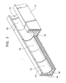
- Fig. 3 is a perspective view illustrating the guide rail body partially cut away to show the oil groove 50.
- Fig. 4 is a longitudinal cross sectional view illustrating the guide rail body and the lid member.
- the bar loader 2 is disposed adjacent to a NC automatic lathe "N" in front thereof.
- the bar loader 2 comprises a base 4 supported by a stand 3 and a guide rail 6 which is supported by the base 4 .
- the guide rail 6 extends straight toward the NC automatic lathe “N” to feed a bar “B” to the NC automatic lathe “N".
- the guide rail 6 comprises a channel -shaped guide rail body 10 whose upper portion is open to receive the bar which is taken out of a stock rack 8 described below, and a lid member 12 which sealingly closes the upper opening of the guide rail body 10. It is to be noted that both ends of the guide rail 6 are open.
- a stock rack 8 for holding a plurality of bars "B” is disposed diagonally above and in parallel to the guide rail 6. Further, a shaft 14 is provided vertically above and in parallel to the guide rail 6. It is rotatably driven by a motor (not shown). A plurality of index plates for taking out the bar “B” from the stock rack 8 are fixed to the shaft 14 at a distance from each other. Furthermore, as shown in Fig. 1 (a), a remnant ejecting outlet 18 having a hatch (not shown) which is opened and closed by a cylinder 17 is provided in a bottom wall of the guide rail body 10. A remnant collecting box 20 is located under the remnant ejecting outlet 18.
- a feeding rod 22 (22') for feeding the bar to the NC automatic lathe “N” is accomodated within the guide rail body 10.
- a finger chuck 24 (24') is provided at a leading end of the feeding rod 22 to hold the trailing end portion of the bar.
- a so-called “flag portion” 26 is mounted on the trailing end of the feeding rod 22 and it extends horizontally out of the upper opening of the guide rail body.
- the flag portion 26 is coupled with an endless chain which runs along a sprocket (not shown).
- a servo motor 28 having an encoder is provided at the rear end portion of the guide rail 6.
- the endless chain is driven by the servo motor 28 via the sprocket to move the feeding rod 22 in forward and backward directions within the guide rail 6.
- a pulse signal which corresponds to a moving distance of the endless chain, that is, a moving distance of the flag portion 26 of the feeding rod 22, is transmitted by the encoder 28 to a controller 30.
- a vibration suppresser 32 for preventing the bar "B” from vibrating is provided at the front end portion of the guide rail 6.
- the vibration suppresser 32 includes four rollers for holding the circumferential surface of the bar "B” between the collet chuck of the NC automatic lathe which holds the leading end portion of the bar "B” and the finger chuck 24 which holds the trailing end of the bar.
- the guide rail body 10 has the channel-like shape with a substantially U-shaped concave portion 36. It defines the bar passageway 34 which extends longitudinally.
- the lid member 12 also has a curved concave portion 38 which extends longitudinally and is opposite from the guide rail body 10.
- a bar feeding passage 42 is formed.
- the cross-section thereof is substantially circular which is defined by a curved surface. Since the bore "D" of the bar feeding passage 42 is slightly larger than the diameter of the bar "d”, a space is formed therebetween.
- each of the guide rail body 10 and the lid member 12 are made of U-shape iron core 46 and resin 48.
- the resin 48 is preferably urethane resin.
- the bar feeding passage 42 is formed with the resin 48 on the iron core 46.
- a plurality of oil grooves 50 are formed by molding the resin 48 on each of the inner wall surfaces of the guide rail body 10 and the lid member 12. When the guide rail body 10 is closed by the lid member 12, each oil groove 50 extends in a circumferential direction therein and forms a substantially annular shape groove.
- the oil grooves 50 are arranged at equal intervals in the longitudinal direction of the guide rail 6.
- the width "W” of the oil grooves 50 in the longitudinal direction and the distance “w” between the adjacent grooves 50 are approximately equal to each other and is about 3 cm in the present embodiment. Further, the depth “e” of the oil groove 50 is about 1 mm.
- the lid member 12 is transversely divided into two portions including the rear lid portion 49 and the front lid portion 51 with respect to a bar feeding direction.
- the lid portions 49, 51 are coupled with the rear cylinder 55 and the front cylinder 57, respectively.
- each lid portion 49, 51 is moved individually and independently between an opening position (shown by the dotted lines in Fig. 2) and a closing position (shown by the solid lines in Fig. 2) by the cylinders 55, 57.
- the flag portion 26 provided at the trailing end of the feeding rod 22 extends out of the guide rail body 10 through the upper opening 40.
- the rear lid portion 49 is moved to the opening position by the cylinder 55 to allow the feeding rod 22 to advance when the flag portion 26 approaches thereto.
- the finger chuck 24 of the feeding rod 22 and the bar both of which rotate at a high speed during the machining process, are accommodated within the bar feeding passage 42 which is closed by the front lid portion 51.
- each of the lid portions 49, 51 is provided with three inlets of the oil injecting inlets 52 ⁇ 62.
- the injecting inlets are located at substantially equal intervals in the longitudinal direction as shown in Fig. 1 (a).
- the entire guide rail 6 and the stock rack 8 are covered with an outer hood 72 to prevent the oil which leaks from both ends of the guide rail 6 from scattering.
- It comprises an upper wall 64, a side wall 66, an end wall 68 and a bottom wall 70.
- the upper wall 64 is hinged to the side wall 66 to enable an access to the guide rail 6.
- the bottom wall extends in the longitudinal direction along the guide rail 6 and is composed of an oil tray 70 which is large enough to receive the oil which leaks from the guide rail 6.
- the oil tray 70 collects the oil which flows out of the ends of the guide rail 6 as well as the oil collected by the upper wall 64, the side wall 66 and the end wall 68 of the oil dispersion preventive hood. Further, as shown in Fig.
- two oil pumps 76, 78 are mounted on the oil tray 70. They are for pumping the oil stored in the oil tray 70 and for supplying the oil to the oil injecting inlets 52 ⁇ 62.
- Each of the oil pumps 76, 78 is connected to the oil injecting inlets 52 ⁇ 62 by a tube (not shown), i.e., the rear three oil injecting inlets 52 ⁇ 56 are connected to the first oil pump 76 and the front three oil injecting inlets 58 ⁇ 62 are connected to the second oil pump 78.
- each of the oil pumps 76, 78 is provided with a thermal sensor 80. Further, a thermal sensor 82 is also mounted on the side wall of the guide rail body 10. The temperature of the oil pumps may rise caused by clogging of the pumps which may result in ignition of the ambient oil mist. Further, the guide rail 6 may be heated by the friction between the bar and the inner wall surface of the guide rail 6 when enough quantity of oil is not supplied to the guide rail 6 due to the clogging of the oil pumps.
- a controller 30 determines whether or not the temperature of the oil pump 76, 78 or the guide rail 6 has exceeded a predetermined temperature in response to the signal from the thermal sensor 80, 82, the controller 30 actuates an alarm to inform the operator if such abnormality occurs.
- a float switch 90 for detecting whether or not there is the oil in the oil tray is provided in the vicinity of the oil tray 70.
- the operation of the oil pumps 76, 78 without the oil in the oil tray may also cause the fire.
- the controller 30 actuates the alarm to let the operator know it as stated above.
- the controller 30 controls the cylinders 55, 57 to open and close the lid portions 49, 51 and the oil pumps 76, 78 to supply the oil to the oil injecting inlets 52 ⁇ 62.
- the bar loader 2 in accordance with the present invention is operated as follows. First, the two lid portions 49, 51 are at the opening position so that the upper opening 40 of the guide rail body 10 is open. Further, the feeding rod 22 is at the retracted position at the rear side of the guide rail 6 as shown in Fig. 1 (b) at the reference numeral 22. The index plate 16 is rotated to take out one bar from the stock rack 8 and to supply the bar into the guide rail body 10 through the upper opening 40 thereof. Next, a pusher (not shown) pushes the trailing end of the bar in the guide rail 6 toward the NC automatic lathe. When the bar advances to the NC automatic lathe, the leading end portion of the bar is clamped by a clamping device.
- the two lid portions 49, 51 are moved to the closing positions by the corresponding cylinders 55, 57 to close the upper opening 40 thereof.
- the feeding rod 22 advances forwardly and stops at the temporally stopping position shown in Fig. 1 (b) by the reference numeral 22' where the finger chuck 24 is covered by the lid member 12.
- a clamping device moves backwardly whereby the trailing end portion of the bar is inserted into the finger chuck 24 provided at the leading end of the feeding rod 22.
- the entire finger chuck 24 of the feeding rod 22 and the bar are accommodated within the bar feed passage 42 as shown in Fig. 1 (b).
- the guide rail 6 is a so-called half-closed system, i.e., the upper opening 40 of the guide rail body 10 is sealingly closed by the lid member 12 while both ends thereof are open to allow the oil to flow out therefrom whereas some of the oil remains in the oil grooves 50.
- the oil stored in the oil groove 50 is forced to move along the circumferential surface of the bar.
- the oil is guided along the oil groove 50 which substantially has the annular shape to form a substantially annular oil layer around the bar.
- the hydrodynamic centripetal force of the oil acts on the circumferential surface of the bar and the bar is moved toward the center of the bar feeding passage 42 of the guide rail 6. Since the oil grooves 50 are arranged at equal intervals with respect to the longitudinal direction of the guide rail 6, it enables to prevent the entire bar from making contact with the inner wall surface of the guide rail 6.
- the oil flowing out of the ends of the guide rail 6 and the scattered oil collected by the outer hood is collected in the oil tray 70 located thereunder. It is recycled into the bar passage 42 through the injecting inlets 52 ⁇ 62 into the bar feeding passage 42 by the oil pumps 76, 78.
- the temperature of the oil pumps 76, 78 is monitored by the thermal sensor 80.
- the controller 30 determines that the temperature of the oil pumps 76, 78 has risen above the predetermined temperature, it actuates the alarm to inform the operator.
- the encoder 28 transmits the pulse signal to the controller 30.
- the pulse signal represents the moving distance of the endless chain, that is, the moving distance of the flag portion 26 of the feeding rod 22.
- the controller 30 counts the number of pulse signals transmitted from the encoder 28. Based on the counted value, the position of the flag portion 26 of the feeding rod 22 is detected. The machined front end portion of the bar is separated by a cutting tool of the NC lathe "N".
- the feeding rod 22 advances to move the bar in the forward direction.
- the controller 30 determines that the flag portion 26 of the feeding rod 22 has approached to the rear lid portion 49
- the controller 30 actuates the cylinder 55 to move the rear lid portion 49 to the opening position so as to allow the flag portion 26 to advance forwardly.
- the bar and the finger chuck 24 are covered with the front lid portion 51 and are still accommodated in the bar feeding passage 42.
- the controller 30 stops the oil pump 76 connected to the oil injecting inlets 52 ⁇ 56 located at the rear lid portion 49 while it still keeps actuating the oil pump 78 connected to the oil injecting inlets 58 ⁇ 62 located at the front lid portion 51 to keep supplying the oil to the bar feeding passage 42 so as to supply the oil only to the portion of the passage 42 required. Therefore, it enables to prevent the bar from making contact with the inner wall surface of the guide rail 6 which results in reduction of the vibration and the noise.
- the leading end portion of the bar is cut into pieces as the machining process proceeds.
- the remnant is brought back to the ejecting outlet 18 to be collected in the remnant collecting box 20 by the finger chuck 24.
- the hatch for the ejecting outlet 18 is opened by the cylinder 17.
- the bar loader according to the present embodiment is the so-called half-closed system, i.e., the upper opening 40 of the guide rail body 10 is closed by the lid member 12 whereas both ends are open, the complex mechanism of opening and closing the lid member 12 and the precisely formed parts are not required as in the completely closed system in which the oil is sealingly enclosed in the guide rail 6. Therefore, the problems of the vibration and the noise can be solved by the system having a simple structure.
- all of the oil does not flow out of the ends of the guide rail 6 and some of the oil remains in the oil grooves 50. It enables the oil layer to be formed between the bar and the inner wall surface of the guide rail 6 by the spinning of the bar and to prevent the bar from making contact with the inner wall surface of the guide rail 6 so as to reduce the vibration and the noise.
- the oil is prevented from scattering around. Furthermore, since the oil is collected in the oil tray 70, the oil can be recycled.
- the lid member 12 is divided into two lid portions 49, 51. Therefore, part of the lid member 12 can be opened when the flag portion 26 approaches thereto to allow the flag portion 26 to advance. At the same time, it ensures that the bar and the finger chuck 24 stay inside the bar feeding passage 42 which results in the prevention of the vibration and the noise.
- the oil pumps 76, 78, the guide rail body 10 and the oil tray 70 are provided with the thermal sensor 80, the thermal sensor 36 and the float switch 90, respectively, the accident due to fire can be prevented.
- the lid member 12 sealingly closes the upper opening 40 of the guide rail body 10.
- the upper opening 40 of the guide rail body 10 does not have to be sealed completely.
- a space may be formed between the upper opening 40 of the guide rail body 10 and the lid member 12 or the guide rail does not necessarily have to have the lid member 12.
- the circumferential surface of the bar forces the oil stored in the oil groove 50 of the guide rail body 10 to move along with the inner wall surface of the guide rail 6.
- the oil layer is formed between the lower surface of the bar and the inner wall surface of the guide rail body 10 thereby. It enables to avoid the contact therebetween to reduce the vibration and noise.
- the depth and the width of the oil groove 50, and the distance between adjacent oil grooves 50 may be determined based on the noise level, the quantity of the oil flowing out of the end portions of the guide rail 6, the quantity of the oil to be remained in the oil groove 50, etc.
- the space between the bore of the bar passageway 34 and the diameter of the bar is determined so that the oil layer is formed around the bar.
- the bore of the bar passageway 34 may be relatively larger than the diameter of the bar. Even in this case, the oil flows into the oil grooves 50 of the guide rail body 10 to form the oil layer between the lower surface of the bar and the bottom surface of the inner wall of the guide rail body 10, which enables to avoid the contact therebetween to prevent the vibration and the noise.
- the oil is injected through the oil injecting inlets 52 ⁇ 56 or 58 ⁇ 62 provided in the guide rail body 10 which is closed by the lid portions 49, 51.
- the controller 30 may control the operation of the oil pumps 76, 78 so as to inject the oil only to the middle portion of the longitudinal bar where deflection is the largest.
- the oil is stored in the oil groove 50 in the vicinity of the middle portion of the bar.
- the hydrodynamic centripetal force of the oil makes the deflected portion of the bar to move toward the center of the bar feeding passage 42. It enables to prevent the bar from making contact with the inner wall surface of the guide rail 6.
Applications Claiming Priority (3)
| Application Number | Priority Date | Filing Date | Title |
|---|---|---|---|
| JP20425197 | 1997-07-30 | ||
| JP204251/97 | 1997-07-30 | ||
| JP20425197A JP3262745B2 (ja) | 1997-07-30 | 1997-07-30 | 棒材供給機 |
Publications (2)
| Publication Number | Publication Date |
|---|---|
| EP0894559A1 true EP0894559A1 (de) | 1999-02-03 |
| EP0894559B1 EP0894559B1 (de) | 2003-03-19 |
Family
ID=16487368
Family Applications (1)
| Application Number | Title | Priority Date | Filing Date |
|---|---|---|---|
| EP98306065A Expired - Lifetime EP0894559B1 (de) | 1997-07-30 | 1998-07-30 | Stangenzuführvorrichtung |
Country Status (5)
| Country | Link |
|---|---|
| US (1) | US6099226A (de) |
| EP (1) | EP0894559B1 (de) |
| JP (1) | JP3262745B2 (de) |
| DE (1) | DE69812242T2 (de) |
| TW (1) | TW376341B (de) |
Families Citing this family (5)
| Publication number | Priority date | Publication date | Assignee | Title |
|---|---|---|---|---|
| ITMI20012537A1 (it) * | 2001-11-30 | 2003-05-30 | Cucchi Pietro Spa | Alimentatore automatico di barre per torni plurimandrino |
| JP4542040B2 (ja) * | 2003-11-28 | 2010-09-08 | シチズンホールディングス株式会社 | 数値制御自動旋盤の棒材供給装置 |
| US8051755B2 (en) | 2006-10-24 | 2011-11-08 | Alps Tool Co., Ltd. | Bar feeder, feed rod vibration prevention support of material feeder and vibration stopper of material feeder |
| EP2139631B1 (de) * | 2007-04-27 | 2011-04-20 | Moser Mechanik | Zentrierfutter zur zentrierung von materialstangen |
| JP5519604B2 (ja) * | 2011-09-09 | 2014-06-11 | 育良精機株式会社 | 棒材供給機 |
Citations (4)
| Publication number | Priority date | Publication date | Assignee | Title |
|---|---|---|---|---|
| US3145513A (en) * | 1962-12-13 | 1964-08-25 | Gordon H Porath | Steady rests |
| US4628779A (en) * | 1984-03-27 | 1986-12-16 | Societe De Vente Et De Fabrication Pour Le Decolletage Lns Sa | Feed apparatus for machine tools |
| JPS63278704A (ja) * | 1987-05-08 | 1988-11-16 | Alps Tool:Kk | 棒材供給機の棒材支持パイプ |
| US5617769A (en) * | 1994-10-14 | 1997-04-08 | Hardinge Brothers, Inc. | Thermally compliant bar feeding machine |
Family Cites Families (9)
| Publication number | Priority date | Publication date | Assignee | Title |
|---|---|---|---|---|
| ES504082A0 (es) * | 1980-07-18 | 1982-12-01 | Sameca Sa | Equipo para el guiado de la bana de material, de diversos diametros, mecanizados en un torno automatico. |
| US4421446A (en) * | 1981-07-23 | 1983-12-20 | Manurhin Automatic Division Of Mitac, Inc. | Bar feed mechanism |
| JPS6071102A (ja) * | 1983-09-27 | 1985-04-23 | Citizen Watch Co Ltd | 棒材供給装置 |
| DE3668816D1 (de) * | 1985-09-10 | 1990-03-15 | Sameca Sa | Stangenfuehrungsvorrichtung. |
| GB2196557B (en) * | 1986-10-24 | 1990-10-17 | Alps Tool Kk | Rod feeding machine. |
| DE3877067T2 (de) * | 1987-06-24 | 1993-07-01 | Sameca Sa | Stangenfuehrungsvorrichtung fuer drehautomat und verfahren zu ihrer fertigung. |
| DE3926841A1 (de) * | 1989-08-14 | 1991-02-21 | Hainbuch Praez Spannwerkzeug | Fuehrungsvorrichtung fuer stangenfoermige werkstuecke von drehmaschinen |
| US5333524A (en) * | 1992-08-31 | 1994-08-02 | Spego, Inc. | Pressure stabilizer for barfeed apparatus |
| DE4431814A1 (de) * | 1994-09-07 | 1996-03-14 | Index Werke Kg Hahn & Tessky | Automatische Werkstoffstangen-Zuführeinrichtung für Werkzeugmaschinen, insbesondere Drehautomaten |
-
1997
- 1997-07-30 JP JP20425197A patent/JP3262745B2/ja not_active Expired - Lifetime
-
1998
- 1998-07-28 TW TW087112348A patent/TW376341B/zh not_active IP Right Cessation
- 1998-07-29 US US09/124,923 patent/US6099226A/en not_active Expired - Lifetime
- 1998-07-30 DE DE69812242T patent/DE69812242T2/de not_active Expired - Lifetime
- 1998-07-30 EP EP98306065A patent/EP0894559B1/de not_active Expired - Lifetime
Patent Citations (4)
| Publication number | Priority date | Publication date | Assignee | Title |
|---|---|---|---|---|
| US3145513A (en) * | 1962-12-13 | 1964-08-25 | Gordon H Porath | Steady rests |
| US4628779A (en) * | 1984-03-27 | 1986-12-16 | Societe De Vente Et De Fabrication Pour Le Decolletage Lns Sa | Feed apparatus for machine tools |
| JPS63278704A (ja) * | 1987-05-08 | 1988-11-16 | Alps Tool:Kk | 棒材供給機の棒材支持パイプ |
| US5617769A (en) * | 1994-10-14 | 1997-04-08 | Hardinge Brothers, Inc. | Thermally compliant bar feeding machine |
Non-Patent Citations (1)
| Title |
|---|
| PATENT ABSTRACTS OF JAPAN vol. 013, no. 077 (M - 801) 22 February 1989 (1989-02-22) * |
Also Published As
| Publication number | Publication date |
|---|---|
| EP0894559B1 (de) | 2003-03-19 |
| JP3262745B2 (ja) | 2002-03-04 |
| TW376341B (en) | 1999-12-11 |
| US6099226A (en) | 2000-08-08 |
| JPH1142502A (ja) | 1999-02-16 |
| DE69812242T2 (de) | 2004-01-29 |
| DE69812242D1 (de) | 2003-04-24 |
Similar Documents
| Publication | Publication Date | Title |
|---|---|---|
| EP0142232B1 (de) | Zuführeinrichtung für Stangenstahl | |
| EP0894559B1 (de) | Stangenzuführvorrichtung | |
| EP1293282B1 (de) | Flüssigkeitsaufgabevorrichtung für elektrochemisches abtragen | |
| US7025544B2 (en) | Machine tool and lubricant jetting state detector for machine tool | |
| EP0657243B1 (de) | Electrische entladungsbearbeitungsvorrichtung | |
| EP0111001B1 (de) | Gerät für schneiddrahtfunkenerosionsbearbeitung | |
| EP0906180B1 (de) | Einspritzvorrichtung | |
| GB2082105A (en) | Drawing and cooling wire | |
| EP0507741B1 (de) | Drahtschneide-Elektroentladungsmaschine | |
| DE4009450A1 (de) | Elektrodendrahtzufuhreinrichtung in einer elektrischen drahtschneide- und entladungsmaschine | |
| EP0999003B1 (de) | Stangenbehandlungsgerät und Stangenladegerät | |
| JPH03131441A (ja) | 張出部を備えた機械床 | |
| JP3337637B2 (ja) | 棒材供給機 | |
| JP3561771B2 (ja) | 自動パレット交換装置を有する工作機械のドア開閉機構 | |
| KR960005262B1 (ko) | 와이어 커트 방전 가공장치 | |
| US5866865A (en) | Wire direction changer assembly for a wire electrode spark erosion machine | |
| JP3572133B2 (ja) | 浸漬形ワイヤ放電加工機におけるワイヤ送り装置 | |
| JPH09216130A (ja) | 浸漬形ワイヤ放電加工機における加工槽への加工液供給装置 | |
| WO1986001445A1 (en) | Wire cutting discharge processing machine | |
| JP3193664B2 (ja) | 軽合金射出成形機における材料投入方法およびその装置 | |
| US4335985A (en) | Control apparatus for controlling a feed movement in a gear cutting machine | |
| JPS6057937B2 (ja) | 連続鋳造用パウダ−投入装置 | |
| EP0533944B1 (de) | Kopffuehrungsanlage in einer drahtschneidefunkenerosionsmaschine | |
| CN214446733U (zh) | 橡胶件切割装置 | |
| CN218144316U (zh) | 一种防损伤轴承进料装置 |
Legal Events
| Date | Code | Title | Description |
|---|---|---|---|
| PUAI | Public reference made under article 153(3) epc to a published international application that has entered the european phase |
Free format text: ORIGINAL CODE: 0009012 |
|
| AK | Designated contracting states |
Kind code of ref document: A1 Designated state(s): CH DE FR GB IT LI |
|
| AX | Request for extension of the european patent |
Free format text: AL;LT;LV;MK;RO;SI |
|
| 17P | Request for examination filed |
Effective date: 19990511 |
|
| AKX | Designation fees paid |
Free format text: CH DE FR GB IT LI |
|
| 17Q | First examination report despatched |
Effective date: 20000928 |
|
| GRAG | Despatch of communication of intention to grant |
Free format text: ORIGINAL CODE: EPIDOS AGRA |
|
| GRAG | Despatch of communication of intention to grant |
Free format text: ORIGINAL CODE: EPIDOS AGRA |
|
| GRAH | Despatch of communication of intention to grant a patent |
Free format text: ORIGINAL CODE: EPIDOS IGRA |
|
| GRAH | Despatch of communication of intention to grant a patent |
Free format text: ORIGINAL CODE: EPIDOS IGRA |
|
| GRAA | (expected) grant |
Free format text: ORIGINAL CODE: 0009210 |
|
| AK | Designated contracting states |
Designated state(s): CH DE FR GB IT LI |
|
| REG | Reference to a national code |
Ref country code: GB Ref legal event code: FG4D |
|
| REG | Reference to a national code |
Ref country code: CH Ref legal event code: NV Representative=s name: MICHELI & CIE INGENIEURS-CONSEILS Ref country code: CH Ref legal event code: EP |
|
| REF | Corresponds to: |
Ref document number: 69812242 Country of ref document: DE Date of ref document: 20030424 Kind code of ref document: P |
|
| ET | Fr: translation filed | ||
| PLBE | No opposition filed within time limit |
Free format text: ORIGINAL CODE: 0009261 |
|
| STAA | Information on the status of an ep patent application or granted ep patent |
Free format text: STATUS: NO OPPOSITION FILED WITHIN TIME LIMIT |
|
| 26N | No opposition filed |
Effective date: 20031222 |
|
| REG | Reference to a national code |
Ref country code: FR Ref legal event code: PLFP Year of fee payment: 19 |
|
| REG | Reference to a national code |
Ref country code: FR Ref legal event code: PLFP Year of fee payment: 20 |
|
| PGFP | Annual fee paid to national office [announced via postgrant information from national office to epo] |
Ref country code: FR Payment date: 20170428 Year of fee payment: 20 Ref country code: CH Payment date: 20170621 Year of fee payment: 20 |
|
| PGFP | Annual fee paid to national office [announced via postgrant information from national office to epo] |
Ref country code: DE Payment date: 20170727 Year of fee payment: 20 Ref country code: IT Payment date: 20170710 Year of fee payment: 20 Ref country code: GB Payment date: 20170726 Year of fee payment: 20 |
|
| REG | Reference to a national code |
Ref country code: DE Ref legal event code: R071 Ref document number: 69812242 Country of ref document: DE |
|
| REG | Reference to a national code |
Ref country code: CH Ref legal event code: PL |
|
| REG | Reference to a national code |
Ref country code: GB Ref legal event code: PE20 Expiry date: 20180729 |
|
| PG25 | Lapsed in a contracting state [announced via postgrant information from national office to epo] |
Ref country code: GB Free format text: LAPSE BECAUSE OF EXPIRATION OF PROTECTION Effective date: 20180729 |