EP0894367B1 - Verfahren und vorrichtung zur interferenzunterdrückung mit verschiedenen strahlen, polarisationen und phasenreferenzen - Google Patents
Verfahren und vorrichtung zur interferenzunterdrückung mit verschiedenen strahlen, polarisationen und phasenreferenzen Download PDFInfo
- Publication number
- EP0894367B1 EP0894367B1 EP97918672A EP97918672A EP0894367B1 EP 0894367 B1 EP0894367 B1 EP 0894367B1 EP 97918672 A EP97918672 A EP 97918672A EP 97918672 A EP97918672 A EP 97918672A EP 0894367 B1 EP0894367 B1 EP 0894367B1
- Authority
- EP
- European Patent Office
- Prior art keywords
- scalar
- signal samples
- produce
- impairment
- estimate
- Prior art date
- Legal status (The legal status is an assumption and is not a legal conclusion. Google has not performed a legal analysis and makes no representation as to the accuracy of the status listed.)
- Expired - Lifetime
Links
Images


Classifications
-
- H—ELECTRICITY
- H04—ELECTRIC COMMUNICATION TECHNIQUE
- H04B—TRANSMISSION
- H04B7/00—Radio transmission systems, i.e. using radiation field
- H04B7/02—Diversity systems; Multi-antenna system, i.e. transmission or reception using multiple antennas
- H04B7/04—Diversity systems; Multi-antenna system, i.e. transmission or reception using multiple antennas using two or more spaced independent antennas
- H04B7/08—Diversity systems; Multi-antenna system, i.e. transmission or reception using multiple antennas using two or more spaced independent antennas at the receiving station
- H04B7/0837—Diversity systems; Multi-antenna system, i.e. transmission or reception using multiple antennas using two or more spaced independent antennas at the receiving station using pre-detection combining
- H04B7/0842—Weighted combining
- H04B7/0848—Joint weighting
- H04B7/0854—Joint weighting using error minimizing algorithms, e.g. minimum mean squared error [MMSE], "cross-correlation" or matrix inversion
-
- H—ELECTRICITY
- H04—ELECTRIC COMMUNICATION TECHNIQUE
- H04B—TRANSMISSION
- H04B7/00—Radio transmission systems, i.e. using radiation field
- H04B7/02—Diversity systems; Multi-antenna system, i.e. transmission or reception using multiple antennas
-
- H—ELECTRICITY
- H04—ELECTRIC COMMUNICATION TECHNIQUE
- H04B—TRANSMISSION
- H04B7/00—Radio transmission systems, i.e. using radiation field
- H04B7/02—Diversity systems; Multi-antenna system, i.e. transmission or reception using multiple antennas
- H04B7/04—Diversity systems; Multi-antenna system, i.e. transmission or reception using multiple antennas using two or more spaced independent antennas
- H04B7/08—Diversity systems; Multi-antenna system, i.e. transmission or reception using multiple antennas using two or more spaced independent antennas at the receiving station
- H04B7/0837—Diversity systems; Multi-antenna system, i.e. transmission or reception using multiple antennas using two or more spaced independent antennas at the receiving station using pre-detection combining
- H04B7/0842—Weighted combining
- H04B7/0845—Weighted combining per branch equalization, e.g. by an FIR-filter or RAKE receiver per antenna branch
-
- H—ELECTRICITY
- H04—ELECTRIC COMMUNICATION TECHNIQUE
- H04B—TRANSMISSION
- H04B7/00—Radio transmission systems, i.e. using radiation field
- H04B7/02—Diversity systems; Multi-antenna system, i.e. transmission or reception using multiple antennas
- H04B7/04—Diversity systems; Multi-antenna system, i.e. transmission or reception using multiple antennas using two or more spaced independent antennas
- H04B7/08—Diversity systems; Multi-antenna system, i.e. transmission or reception using multiple antennas using two or more spaced independent antennas at the receiving station
- H04B7/0837—Diversity systems; Multi-antenna system, i.e. transmission or reception using multiple antennas using two or more spaced independent antennas at the receiving station using pre-detection combining
- H04B7/0842—Weighted combining
- H04B7/086—Weighted combining using weights depending on external parameters, e.g. direction of arrival [DOA], predetermined weights or beamforming
-
- H—ELECTRICITY
- H04—ELECTRIC COMMUNICATION TECHNIQUE
- H04B—TRANSMISSION
- H04B7/00—Radio transmission systems, i.e. using radiation field
- H04B7/02—Diversity systems; Multi-antenna system, i.e. transmission or reception using multiple antennas
- H04B7/10—Polarisation diversity; Directional diversity
-
- H—ELECTRICITY
- H04—ELECTRIC COMMUNICATION TECHNIQUE
- H04L—TRANSMISSION OF DIGITAL INFORMATION, e.g. TELEGRAPHIC COMMUNICATION
- H04L1/00—Arrangements for detecting or preventing errors in the information received
- H04L1/02—Arrangements for detecting or preventing errors in the information received by diversity reception
- H04L1/06—Arrangements for detecting or preventing errors in the information received by diversity reception using space diversity
-
- H—ELECTRICITY
- H04—ELECTRIC COMMUNICATION TECHNIQUE
- H04L—TRANSMISSION OF DIGITAL INFORMATION, e.g. TELEGRAPHIC COMMUNICATION
- H04L25/00—Baseband systems
- H04L25/02—Details ; arrangements for supplying electrical power along data transmission lines
- H04L25/03—Shaping networks in transmitter or receiver, e.g. adaptive shaping networks
- H04L25/03006—Arrangements for removing intersymbol interference
- H04L25/03178—Arrangements involving sequence estimation techniques
- H04L25/03331—Arrangements for the joint estimation of multiple sequences
-
- H—ELECTRICITY
- H04—ELECTRIC COMMUNICATION TECHNIQUE
- H04W—WIRELESS COMMUNICATION NETWORKS
- H04W16/00—Network planning, e.g. coverage or traffic planning tools; Network deployment, e.g. resource partitioning or cells structures
- H04W16/24—Cell structures
- H04W16/28—Cell structures using beam steering
Definitions
- the present invention pertains to processing of radio communication signals to offset the effects of multipath fading, time dispersion and channel interference.
- the invention more specifically pertains to performing the above identified signal processing using signals derived from a variety of different antenna designs, or using signals separated into in-phase and quadrature components.
- Non-orthogonal signals, or interference often come from radios operating on the same frequency (i.e. co-channel interference) or from radios operating on neighboring frequency bands (i.e. adjacent-channel interference).
- Non-orthogonal signal sources are referred to as interferers.
- Fading can be mitigated by having multiple receive antennas and employing some form of diversity combining, such as selective combining, equal gain combining, or maximal ratio combining.
- Diversity takes advantage of the fact that the fading on the different antennas is not the same, so that when one antenna has a faded signal, chances are the other antenna does not.
- Time dispersion may be advantageously corrected by using an equalizer.
- a maximum likelihood sequence est6imation (MLSE) equalizer such as described in Digital Communications, 2 nd Ed., by John G. Proakis, Mc-Gaw Hill Book Company, New York, New York, USA, 1989 may be used.
- ISI inter-symbol interference
- channel interference may be reduced by employing array processing techniques with multiple antennas.
- adaptive beamforming can be used to "steer" a null in the antenna pattern in the direction of an interferer.
- U.S. Patent 5,499,272 to Bottomley disclosed a further example of a diversity receiver for signals with multipath time dispersion. This system processes a plurality of diversity branches to produce complex receive data samples and synchronization information.
- the above-described techniques fail to provide a receiver design which could be easily adapted to a variety of antenna configurations, such as phased array antennas or antennas producing signals having different polarizations. It would be desirable to provide a technique for reducing the deleterious effects of signal transmission which would accommodate a wide variety of antenna configurations. There is further need to reduce deleterious effects of signal transmission in the situation where the in-phase and quadrature components of the interference are correlated.
- a method for reducing the effects of signal fading, time dispersion, and interference in a radio communications system using a technique of estimating a channel tap, estimating impairment correlation properties and forming branch metrics, comprising the steps of:
- an apparatus for reducing the effects of signal fading, time dispersion, and interference in a radio communications system using a technique of estimating a channel tap, estimating impairment correlation properties and forming branch metrics comprising:
- a radio transmitter and receiver system for a radio communication system is illustrated schematically in Figure 1.
- the radio communication system may operate using frequency division multiple access (FDMA), time division multiple access (TDMA), or code division multiple access (CDMA), or some combination thereof.
- a transmitter has a digital symbol generator 102 which receives an information carrying signal 101 and generates a corresponding digital symbol sequence, S.
- the symbol sequence S is subjected to digital to analog (D/A) conversion, modulation, pulse shape filtering, amplification, and is transmitted as analog signal Y by digital transmitter 103 according to known techniques.
- D/A digital to analog
- an interferer 108 transmitting signal X which may be non-orthogonal to signal Y.
- Signals Y and X travel through separate radio channels and are intercepted by antennas 104 which are D in number.
- Radio units 105 amplify, downconvert, and filter the received signals according to known methods to produce analog signals.
- Each analog signal is coupled to an analog-to-digital (A/D) converter 106, which converts the analog signal into a received signal sample stream r d (kT s ), where T s is the sample period, the reference numeral k is an integer counter, and the subscript d indicates that the signal arrives from the d th antenna 1 ⁇ d ⁇ D.
- the sampling period T may be less than the symbol period T.
- the received signal sample streams are collected in processor 107, which processes these streams to produce an estimate of the transmitted digital symbol stream, S and.
- transmission function 109 is used to refer to the signal path through digital transmitter 103, the radio transmission channel (not shown in Figure 1), antennas 104, radio units 105 and A/Ds 106 collectively.
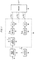
- the processing unit 107 is illustrated in greater detail in Figure 2 where, for simplicity, the number D of antennas is restricted to three: designated a, b, and c.
- Processing unit 107 may be, for example, a Digital Signal Processor (DSP) such as a TMS320C50 manufactured by Texas Instruments.
- DSP Digital Signal Processor
- TMS320C50 manufactured by Texas Instruments.
- the function of processing unit 107 is to produce an estimate of the transmitted digital symbol stream S and which accurately corresponds to the symbol sequence S which was originally transmitted.
- Transmission function 109 produces the received signal sample streams r a (kT s ), r b (Kt s ), and r c (kT s ) which are sent to processing unit 107 where they are processed in accordance with the present invention.
- the received signal sample streams r a (kT s ), r b (kT s ), and r c (kT s ) are coupled to a signal pre-processor, or sync, block 206 where the received signal sample streams are correlated with known timing/synchronization sequences as described, for example, by Giovanna, et al. "Fast Adaptive Equalizers for Narrow-Band TDMA Mobile Radio", IEEE Transactions on Vehicular Technology, Vol.
- the signal pre-processor 206 performs a decimation of the received signal sample streams r a (kT s ), r b (kT s ), and r c (kT s ) to produce one sample per symbol: designated r a (n), r b (n), and r c (n) respectively.
- r a (n), r b (n), and r c (n) respectively.
- fractionally-spaced demodulation more than one sample per symbol is generated.
- Estimating circuits 202a, 202c, and 202c produce channel tap estimates c a ( ⁇ ), c b ( ⁇ ), and c c ( ⁇ ) which are used to model the radio transmission channel associated with each particular antenna.
- Initial channel tap estimates can be obtained from sync correlation values or least-squares estimation according to known techniques. If the channel must be tracked, it is typical to use received data and tentative symbol estimate values generated in the sequence estimation processor 204. Channel tracking is known to those skilled in the art as discussed, for example, in Digital Communications 2nd Ed. by Proakis as previously mentioned, and by A. P. Clark and S. Hariharan, "Adaptive Channel Estimates for an HF Radio Link", IEEE Trans. on Communications, vol. 37, pp. 918-926, Sept. 1989.
- the channel tap estimates c a ( ⁇ ), c b ( ⁇ ), and c c ( ⁇ ) are coupled to the input of the branch metric processor 203.
- the estimate of the impairment correlation properties comprises information regarding the impairment correlation properties between the receive antennas 104.
- the impairment correlation estimator uses impairment process estimates to update and possibly track the estimate of the impairment correlation properties which is discussed in further detail in the ensuing text and figures.
- Branch metric processor 203 uses received signal samples r a (n), r b (n), and r c (n), channel tap estimates c a ( ⁇ ), c b ( ⁇ ), and c c ( ⁇ ), and the estimate of the impairment correlation properties to form branch metric M h (n). This branch metric is used, for example, in a sequence estimation processor 204 to develop tentative and final estimates of the transmitted symbols.
- the transmission function 109 is illustrated in greater detail in Figure 3 where, for simplicity, the number of interferers is restricted to one. It will be apparent to one skilled in the art that the present invention may also be used for the case where there are two or more interferers.
- the transmit function 109 begins with the signal path for the symbol sequence S through digital transmitter 103 which transmits analog signal Y.
- the analog signal Y propagates through a separate radio transmission channel to each of the three receiver antennas: radio channel 301a to receiver antenna 104a, radio channel 301b to receiver antenna 104b, and radio channel 301c to receiver antenna 104c.
- interference signal X also propagates through three other separate radio channels 302a-302c to receiver antennas 104a-104c respectively.
- Radio channels 301a-301c and 302a-302c may introduce fading and time dispersion.
- Omnipresent thermal noise processes n a - n c are also received by receiver antennas 104a-104c respectively.
- Each antenna 104a-104c is coupled to a radio unit 105a-105c respectively which amplifies, downconverts, and filters the received signals according to known methods to produce an analog signal.
- Each analog signal is coupled to an analog-to-digital (A/D) converter 106a-106c which converts the analog signals into received signal sample streams r a (kT s ), r b (kT s ), and r c (kT s ).
- log-polar signal processing As described in U. S. Patent 5,048,059 to Dent.
- a conversion from log-polar to rectangular samples is made, so that, for example, I and Q samples, sometimes referred to as complex samples, are used.
- log-polar signal processing initially, a limiting receiver which provides signal strength and phase samples can be used, and adaptive gain control can be made simple.
- hypothesized symbol values s h (n) are filtered by channel tap estimates c a ( ⁇ ), c b ( ⁇ ), and c c ( ⁇ ) to produce hypothesized received samples r a,h (n), r b,h (n), and r c,h (n) for each antenna.
- the differences between the hypothesized r a,h (n)-r c,h (n) and the actual r a (n)-r c (n) received signal sample streams, referred to as the hypothesis errors give an indication of how good a particular hypothesis is.
- the squared magnitude of the hypothesis error is used as a metric to evaluate a particular hypothesis.
- the metric is accumulated for different hypotheses for use in determining which hypotheses are better using the sequence estimation algorithm.
- This process may be efficiently realized using the Viterbi algorithm, which is a known form of dynamic programming.
- a description of the Viterbi algorithm may be found in Forney, G., "The Viterbi Algorithm", Proc. of the IEEE, vol. 61, pp. 268-278, March, 1973.
- other sequence estimation algorithms such as the M-algorithm, may also be used.
- an MLSE equalizer there are states associated with different symbol sequence hypotheses s h (n). At a given iteration, there are previous states: each associated with an accumulated metric. Each pairing of a previous state with a current state results in a branch metric, M h (n). The candidate metric for a current state is then the sum of the branch metric M h (n) and the previously accumulated metric. For each current state, the previous state which gives the smallest candidate metric is selected as the predecessor state, and the smallest candidate metric becomes the accumulated metric for the current state. For metric combining, as described in aforementioned U.S.
- N t is the number of channel taps estimated per antenna and K a , K b , K c are weighting coefficients for antennas 104a-104c respectively.
- This system takes advantage of the fact that, from a diversity and equalization point-of-view, the impairment (interference + noise) on multiple receive antennas 104 is often correlated at any specific moment in time, even though, on the average, it may be uncorrelated. By expanding diversity combining techniques to exploit this correlation, significant gains are realized. For optimal performance, a whitening, or decorrelation, process may be applied and the optimum branch metric may include the inverse of the impairment correlation matrix.
- a (n) R zz (n) -1 , or a related quantity
- e h (n) r(n)-c(n)s h (n)
- the time varying nature of the channel and the impairment correlation are denoted with time index n.
- the R zz (n) matrix is referred to as the impairment correlation matrix at discrete time, n.
- the A (n) matrix i.e ., the A-matrix
- R zz (n) and A (n) are specific examples of impairment correlation properties of which other forms are known.
- A-matrix is used generically to refer to any estimate of the impairment correlation properties.
- the impairments on antennas 104a-104c at time n are designated by z a (n), z b (n), and z c (n) respectively.
- e h (n) is an estimate of the impairment process.
- the A-matrix, A (n) is the inverse of the impairment correlation matrix R zz (n).
- the A-matrix reduces to diagonal matrix D.
- s det (n) [s det (n)s det (n-1) ⁇ ] T
- s det (n) is the known or detected symbol sequence at time n.
- Determination of the A-matrix for use in the present invention can be performed in a number of ways depending upon the specific application and the required performance.
- the simplest approach is to use a fixed set of values for the A-matrix, stored in memory. These values depend primarily on the configuration of the receive antennas and on the carrier frequencies being employed.
- An alternative approach is to determine the A-matrix from synchronization information and to keep the A-matrix values constant between synchronization, or other, known fields. At each new occurrence of the synchronization field, the A-matrix can be recomputed, with or without use of the previous A-matrix values.
- Another alternative approach is to use synchronization fields to initialize, or improve, the A-matrix values and then to use decisions made on the data field symbols to track the A-matrix values.
- the A-matrix comprises information regarding the impairment correlation properties between the antennas 104a, 104b, and 104c
- standard estimation methods for estimating correlation or inverse correlation matrices can be applied.
- impairment values can be obtained by taking the differences between the received signal sample streams r a (n)-r c (n) and the hypothesized received signal sample streams r a,h (n)-r c,h (n). At time n, this gives a vector of impairment values, denoted z(n); one value for each antenna.
- elements in the vector correspond to different antennas 104.
- R(n) ⁇ R(n-1) +Kz(n)z H (n)
- the A-matrix can be expressed and estimated in a variety of ways, as will be apparent to those skilled in the art. See, for example, the book by S. Haykin, Adaptive Filter Theory, Second Edition, Prentice-Hall, Englewood Cliffs, N.J., 1991.
- the present invention may also be applied to the blind equalization problem in which known synchronization sequences are absent. In this case, the A-matrix is estimated in a manner similar to how the channel is estimated.
- a processor 107 having a symbol-spaced (i.e., T-spaced) equalizer where the channel must be tracked over the data field, or burst.
- T-spaced symbol-spaced
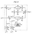
- the branch metric processor 203 is illustrated in greater detail in Figure 4 where, for simplicity, the number of antennas is further restricted to two: designated a and b.
- This particular embodiment has usefulness in that the use of two receive antennas is common in many cellular systems which already employ some form of diversity combining. As before, it will be apparent to those skilled in the art that this embodiment may also be employed in the case where there are three or more antennas.
- the impairment correlation matrix R zz and the inverse impairment correlation matrix A are defined as follows:
- the variable p aa denotes the impairment power received on antenna a;
- the variable p bb denotes the impairment power received on antenna b.
- the off-diagonal matrix elements are the cross correlation values:
- p ab denotes the correlation of the impairment received on antenna a with the conjugate of that received on antenna b.
- a symbol sequence generator 410 generates hypothesized symbol sequences s h (n). These sequences are filtered in filters 400 using channel tap estimates c a ( ⁇ ) and c b ( ⁇ ) for antennas a and b to produce hypothesized received signal samples r a,h (n) and r b,h (n), respectively.
- the hypothesized received signal samples, r a,h (n) are subtracted from the actual received signal samples from antenna a, r a (n), in summing junction 401 to produce error signal e a,h (n).
- Blocks 403 form the squared magnitudes of the error signals e a,h (n) and e b,h (n).
- the squared magnitude for error signal e a,h (n) is multiplied at junction 406 by multiplier m aa , the result being coupled to summing junction 408.
- the squared magnitude for error signal e b,h (n) is multiplied at junction 407 by multiplier m bb , the result being coupled to summing junction 408.
- multiplier 404 forms the product of e a,h (n) and e* b,h (n), the product of which is subsequently multiplied by multiplier m ab in multiplier 405, forming the real part only. The result is subtracted in summing junction 408, the output of which is the branch metric M h (n).
- w term is common to the branch metric calculation and may be applied in a different manner or even omitted when the denominator to w approaches zero.
- p ab (n+1) ⁇ p ab (n) +e a (n) e b * (n)K
- p bb (n+1) ⁇ p bb (n) +
- K is a scaling factor which, if equal to unity, is dropped from the calculation to reduce the number of computations.
- K may be derived from ⁇ which is the so-called "forgetting factor".
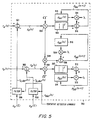
- FIG. 5 A schematic illustration of the impairment correlation matrix update is shown in Figure 5.
- Tentative detected symbol values s det (n) from sequence estimation processor 204 are filtered in filters 500 using channel tap estimates c a ( ⁇ ) and c b ( ⁇ ) from channel tap estimators 202 for antennas a and b to produce expected received samples r a,det (n) and r b,det (n), respectively.
- Impairment signal z a (n) is produced by subtracting, in summing junction 501 r a,det (n) from the actual received signal samples from antenna a, r a (n).
- impairment signal z b (n) is produced by subtracting, in summing junction 502 r b,det (n) from the actual received signal samples on antenna b, r b (n). If the tentative detected symbol values are correct and the channel tap estimates are accurate, then error signals z a (n) and z b (n) represent the impairment received on antennas a and b respectively. Impairment signals z a (n) and z b (n) are scaled by the root of the scaling factor K in multipliers 503 and 505 respectively to produce scaled impairment signals which are coupled to blocks 506 and 507, respectively.
- the impairment power received on antenna a, p aa (n), is multiplied in multiplier 511 by the forgetting factor, ⁇ , and summed in junction 510 with the squared magnitude of the scaled impairment signal from block 506 to produce the updated impairment power p aa (n+1).
- the value of p aa (n+1) is then used to overwrite the memory location 515 of the previous impairment power p aa (n).
- the previous impairment power received on antenna b, p bb (n) is multiplied in multiplier 513 by the forgetting factor, ⁇ , and summed in junction 512 with the squared magnitude of the scaled error signal from block 507 to produce the updated impairment power p bb (n+ 1) which is used to overwrite the memory location 514 of the previous impairment power p bb (n).
- the scaled error signal from multiplier 503 is multiplied with the conjugate of the scaled error signal from multiplier 505 in junction 504.
- the previous cross-correlation p ab (n) stored in memory 516, is scaled by the forgetting factor in multiplier 509.
- junction 504 The output of junction 504 is summed in junction 508 with the output of multiplier 509 to yield the updated cross correlation p ab (n+1). As before, the updated value p ab (n+1) is used to overwrite the memory location 516 of the previous value p ab (n).
- interference rejection is applied to signals that correspond to N different antenna elements, wherein the N antenna elements are selected from a number M ⁇ N possible antenna signals. Additionally, these selected antenna element signals may have passed through a specific beamforming process and/or the signals may come from antennas that have different polarizations. As a specific exemplary embodiment, three different cases of multi-element receive antennas are considered which employ the use of horizontal and vertical polarizations. However, other types of orthogonal polarizations may be used, such as plus and minus 45 degrées, or right and left circular.
- FIG. 6 shows the first embodiment where M co-phased antenna elements (which may be a combination of both horizontally and vertically polarized elements) given by signals 6010 through 6012 are first passed through a fixed beamforming processor 601 that results in M beamspace signals 6020 through 6021.
- the antenna elements in this embodiment typically are spaced closely (e.g. a half of a wavelength) together.
- the selection processor 602 chooses N beamspace signals 6022 through 6023 for further IRC processing.
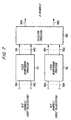
- Figure 7 is an embodiment where M co-phased antenna element signals 7001 through 7004 are passed through two beamforming processors 701 and 702, one each for the vertically and horizontally polarized elements.
- Signals 7001 through 7002 correspond to the vertical antenna elements and are processed by 701 giving outputs 7011 through 7012
- signals 7003 through 7004 correspond to the horizontal antenna elements and are processed by 702 giving outputs 7021 through 7022 .
- Signals 7011 through 7012 and 7021 through 7022 are processed by the selection processor 703 and N output signals 7030 through 7031 are selected.
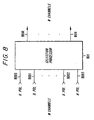
- Figure 8 is an embodiment that uses sector antennas, where the antennas may be either vertically or horizontally polarized.
- the antenna signals are 8000 through 8003 and are processed by the selection processor 801 to generate N output signals 8010 through 8011 .
- antennas with the same polarization may be physically separated (e.g. 10-20 wavelengths).
- FIGS 6-8 are not restricted to the use of horizontal and vertical polarizations.
- other types of orthogonal polarizations may be used, such as plus and minus 45 degrees, or right and left circular.
- more than two beam processors may be employed. For instance, different beam processors may be assigned to process groups of signals originating from different spatially separated groups of antenna elements.
- Figure 9 shows an embodiment of the branch selection processor.
- Each input signal branch 9000 through 9001 is first filtered by 901 through 902 and then passed through some signal quality measure device 903 through 904 which generates measures 9030 through 9040 that is used to compare the signal's quality relative to the other signals.
- the M signals 9010 through 9020 are sent to the selection multiplexor 905 , which chooses the N signals (out of M) that have the best measure 9030 through 9040 .
- the measure criteria may be defined to represent one or more of the following qualities: measured instantaneous branch power; measured average branch power; beam center direction relative to desired signal direction; signal quality as measured from sync word (measured (S+N)/N). "S” denotes signal power, whereas "N” denotes impairment power.
- the selection may be constrained to keeping at least one vertically polarized and one horizontally polarized signal. For example, choosing the horizontal beam with the maximum power and the vertical beam with the maximum power performs best in certain circumstances (such as the presence of Rayleigh fading). Again, other types of orthogonal signals may be used.
- Still a further embodiment may dispense with the selection processor altogether.
- the processor 107 is fed all of the M signals received from the antenna elements.
- This embodiment may employ antenna elements producing orthogonally polarized signals and/or one or more fixed beam processors as discussed above.
- interference rejection is applied to signals that correspond to different phase references. Normally, the in-phase (I) and quadrature (Q) components of the baseband signal are combined into one complex signal. However, when the interference is not rotationally invariant, then the two components must be treated as separate, scalar received signals. See, for example, B. Picinbono, "On circularity", IEEE Trans. Sig. Proc., Vol. 42, pp. 3473-3482, Dec. 1994.
- the channel tap estimates are denoted c ( ⁇ ), and there are N t of them.
- the real matrices A (n) and R -1 / WW ( n ) are specific examples of scalar impairment correlation properties of which other forms are known. Throughout the following, the term A-matrix is used generically to refer to any estimate of the impairment correlation properties.
- the A-matrix can be estimated and tracked in a variety of ways.
- One way is to form impairment samples z(n) by subtracting expected received samples from the actual received samples.
- Scalar impairment vector w(n) is then given by the equation given above.
- A( n ) R -1 WW ( n )
- p( n ) A( n -1)w( n ) Because the A-matrix is symmetric, only the elements on the diagonal and above need
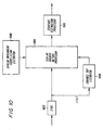
- processor given in Figure 10.
- the received signal is coupled to a signal pre-processor or sync, block 1002, where timing and synchronization information are determined, producing synchronized complex received samples r(n) .
- Channel tap estimator 1004 produces channel tap estimates c( ⁇ ) which model the fading, dispersive channel. These channel tap estimates are coupled to scalar branch metric processor 1006.
- the estimate of the impairment correlation properties includes information regarding the impairment correlation properties between the I and Q components of the received signal, which are scalar quantities.
- Scalar branch metric processor 1006 uses the received signal samples r(n) , channel tap estimates c( ⁇ ) , and an estimate of the impairment correlation properties to form branch metric M h (n) . This branch metric is used in sequence estimation processor 1010 to develop tentative and final estimates of the transmitted symbols.
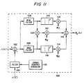
- a symbol sequence generator 1124 generates hypothesized symbol sequences s h (n) . These sequences are filtered by filter 1104 using channel estimates c( ⁇ ) to produce hypothesized received signal samples. The hypothesized received signal samples are subtracted from the actual received signal samples in summing junction 1102 to produce complex error signals.
- the real filter 1108 only passes the real part (in-phase component) of the complex error signals, and the image filter 1106 only passes the imaginary part (quadrature component) of the complex error signals.
- the real part of the error signal is squared in block 1110 then multiplied by multiplier m ll in block 1132, the result being coupled to summing junction 1116.
- the imaginary part of the error signal is squared in block 1118 then multiplied by multiplier m QQ in block 1114, the result being coupled to summing junction 1116.
- the real and imaginary parts of the error signal are multiplied together in block 1134, multiplied by multiplier m IQ in block 1112, then coupled to summing junction 1116.
- the output of summing junction 1116 is the branch metric M h ( n ).
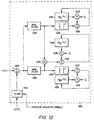
- FIG. 12 A specific embodiment of the scalar impairment correlation estimator is illustrated in Figure 12.
- Known or tentatively detected symbol values from sequence estimating processor 1010 are filtered by filter 1232 using channel tap estimates c( ⁇ ) from channel tap estimator 1004 to produce estimated received samples.
- Impairment samples are produced by subtracting estimated received samples from actual received samples in summing junction 1202.
- the real filter 1204 only passes the real parts (in-phase components) of the impairment samples, and the image filter 1206 only passes the imaginary parts (quadrature components) of the impairment samples.
- the in-phase components of the impairment samples are squared in block 1220 and provided to summing junction 1228.
- the in-phase impairment power estimate p II stored in memory 1224, is scaled in junction 1222 by scale factor ⁇ and provided to summing junction 1228. The output of junction 1228 gives the updated power estimate, which is written into memory 1224.
- the quadrature components of the impairment samples are squared in block 1210 and provided to summing junction 1212.
- the quadrature impairment power estimate p QQ stored in memory 1208, is scaled in junction 1214 by scale factor and provided to summing junction 1212. The output of junction 1212 gives the updated power estimate, which is written into memory 1208.
- the in-phase and quadrature components of the impairment samples are multiplied together in block 1250 and provided to summing junction 1216.
- the in-phase/quadrature cross-correlation estimate p IQ stored in memory 1218, is scaled in junction 1230 by scale factor ⁇ and provided to summing junction 1216.
- the output of junction 1216 gives the updated cross-correlation estimate, which is written into memory 1218.
- Per-Survivor processing techniques can be used to improve performance. For example, there can be one or more sets of channel tap estimates and impairment correlation estimates per state in the sequence estimation processor. This allows immediate updating of estimates, without the need for a decision delay to obtain reliable tentatively detected symbols.
- section B all of the techniques discussed in section B (above) can be employed here to cull out a number of N signals from a larger number of M signals prior to performing interference rejection combining using a scalar branch matrix processor.
- interference rejection is applied to sets of signals.
- the resulting metrics are then simply added together, with a possible weighting prior to adding. This trades performance for a reduction in complexity.
- the selection criteria can be adaptive, based on impairment correlation measurements, signal strength measurements, or other criteria. Also, the selection may be fixed.
- Figure 13 is an embodiment of processor 107 from Figure 1, where 2 antennas and fractionally-spaced sampling by a factor of 2 are used. Thus, for each antenna, two symbol-spaced data sequences are formed, corresponding to two sampling phases.
- Sync blocks 1302 and 1304 take the oversampled signal streams from antennas a and b and produce two symbol-spaced sample streams each. Denoting the antennas with subscripts a and b and the sampling phases with subscripts 0 and 1, the four resulting received signal sample sequences are denoted r a0 (n), r a1 (n), r b0 (n) and r b1 (n).
- the embodiment uses a fixed selection criteria, so that interference rejection is applied to the pair ⁇ r a0 (n), r b0 (n) ⁇ and the pair ⁇ r a1 (n), r b1 (n) ⁇ .
- received signal sample streams r a0 (n) and r b0 (n) are provided to branch metric processor 1306. Also provided to branch metric processor 1306 are channel tap estimates corresponding to streams r a0 (n) and r b0 (n), which are computed in channel tap estimators 1310 and 1312. Impairment correlation estimates corresponding to streams r a0 (n) and r b0 (n) are provided by impairment correlation estimator 1314.
- received signal sample streams r a1 (n) and r b1 (n) are provided to branch metric processor 1308. Also provided to branch metric processor 1308 are channel tap estimates corresponding to streams r a1 (n) and r b1 (n), which are computed in channel tap estimators 1316 and 1318. Impairment correlation estimates corresponding to streams r a1 (n) and r b1 (n) are provided by impairment correlation estimator 1320.
- branch metrics from branch metric processors 1306 and 1308 are summed in added 1322 , which produces a combined branch metric.
- the combined branch metric is then provided to sequence estimation processor 1324, which develops tentative and final estimates of the transmitted symbol sequence.
Landscapes
- Engineering & Computer Science (AREA)
- Computer Networks & Wireless Communication (AREA)
- Signal Processing (AREA)
- Power Engineering (AREA)
- Physics & Mathematics (AREA)
- Mathematical Physics (AREA)
- Radio Transmission System (AREA)
- Error Detection And Correction (AREA)
- Digital Transmission Methods That Use Modulated Carrier Waves (AREA)
- Monitoring And Testing Of Transmission In General (AREA)
Claims (10)
- Ein Verfahren zum Reduzieren der Wirkungen eines Signalschwunds, einer zeitlichen Steuerung und einer Interferenz in einem Kommunikationssystem unter Verwendung einer Technik zum Schätzen eines Kanalabgriffs, zum Schätzen von Beeinträchtigungskorrelationseigenschaften und zum Bilden von Zweigmetriken, enthaltend die Schritte:dadurch gekennzeichnet, dass der Schritt (e) das Bilden von skalaren Zeigmetriken (Mh(n)) in einem skalaren Zweigmetrikprozessor (1006) enthält, unter Verwendung der empfangenen Signalabtastwerte, der Kanalabgriffschätzung ((c(τ)), und der skalaren Schätzung der Beeinträchtigungskorrelationseigenschaften, und Trennung der empfangenen Signalabtastwerte in gleichphasige ((I(n)) und Quadratur (Q(n)) Komponenten und Verarbeiten dieser Komponenten so als ob ihr Ursprung die zwei jeweiligen Skalarkanäle sind.(a) Empfangen eines Funksignals bei zumindest einem Antennenelement zum Repräsentieren einer Übertragungssymbolsequenz;(b) Verarbeiten des Funksignals zum Erzeugen empfangener Signalabtastwerte ((r(n)) für die mindestens eine Antenne;(c) Schätzen eines Kanalabgriffs für die zumindest eine Antenne zum Erzeugen einer Kanalabgriffschätzung (c)τ));d) Schätzen skalarer Beeinträchtigungskorrelationseigenschaften zwischen den empfangenen Signalabtastwerten zum Erzeugen einer Schätzung von skalaren Beeinträchtigungskorrelationseigenschaften;(e) Bilden skalarer Zweigmetriken (Mh(n)); und(f) Einsetzen der skalaren Zweigmetriken in einem Sequenzschätzalgorithmus zum Schätzen der übertragenen Symbolsequenz;
- Ein Verfahren nach Anspruch 1, bei dem der Bildungsschritt (e) enthält:(g) Erzeugen hypothetischer Symbolsequenzen;(h) Filtern der hypothetischen Signalsequenzen mit der Kanalabgriffschätzung zum Erzeugen hypothetischer empfangener Signalabtastwerte für die zumindest eine Antenne;(i) Subtrahieren der hypothetischen empfangenen Signalabtastwerte anhand der empfangenen Signalabtastwerte zum Erzeugen komplexer Fehlersignale; und(j) Verarbeiten der komplexen Fehlersignale mit der skalaren Schätzung der Beeinträchtigungskorrelationseigenschaften zum Erzeugen von Zweigmetriken.
- Ein Verfahren nach Anspruch 2, bei dem der Bildungsschritt (j) ferner enthält:(k) Extrahieren einer gleichphasigen Komponente von dem komplexen Fehlersignal und Extrahieren einer Quadraturkomponente von dem komplexen Fehlersignal;(l) Verarbeiten der gleichfasrigen Komponente und der Quadraturkomponente zum Erzeugen der Zweigmetriken.
- Ein Verfahren nach Anspruch 1, bei dem der Schätzschritt (d) enthält:(g) Erzeugen vorläufiger detektierten Symbolsequenzen;(h) Filtern der vorläufigen detektierten Symbolsequenzen mit der skalaren Kanalabgriffschätzung zum Erzeugen geschätzter empfangener Signalabtastwerte für die zumindest eine Antenne;(i) Subtrahieren der geschätzten empfangenen Signalabtastwerte von den empfangenen Signalabtastwerten zum Erzeugen von Beeinträchtigungssignalabtastwerten; und(j) Verarbeiten der Beeinträchtigungssignalabtastwerte mit der Schätzung der skalaren Beeinträchtigungskorrelationseigenschaften zum Erzeugen einer aktualisierten Schätzung der skalaren Beeinträchtigungskorrelationseigenschaften.
- Ein Verfahren nach Anspruch 4, bei dem der Bildungsschritt (j) ferner enthält:(k) Extrahieren einer gleichfasrigen Komponente von den Beeinträchtigungssignalabtastwerten und Extrahieren einer Quadraturkomponente von den Beeinträchtigungssignalabtastwerten;(l) Verarbeiten der gleichfasrigen Komponenten der Quadraturkomponente zum Erzeugen einer aktualisierten Schätzung der skalaren Quadrationseigenschaften.
- Ein Gerät zum Reduzieren der Wirkungen des Signalschwunds der zeitlichen Steuerung und einer Interferenz in einem Kommunikationssystem unter Verwendung einer Technik zum Schätzen eines Kanalabgriffs zum Schätzen von Beeinträchtigungskorrelationseigenschaften und zum Bilden von Zweigmetriken, enthaltend:dadurch gekennzeichnet, dass die Vorrichtung (1006) zum Bilden skalarer Zweigmetriken (Mh(n)) eine Vorrichtung zum Bilden skalarer Zweigmetriken in einem Skalarzweigmetrikprozessor enthält, unter Verwendung der empfangenen Signalabtastwerte, der Kanalabgriffschätzungen und der Skalarschätzung der Beeinträchtigungskorrelationseigenschaften, sowie eine Vorrichtung zum Separieren der empfangenen Signalabtastwerte in gleichphasige (I(n)) und Quadratur (Q(n)) Komponenten und zur Verarbeiten dieser Komponenten so, als ob ihr Ursprung die zwei jeweiligen Skalarkanäle sind.eine Vorrichtung zum Empfangen eines Funksignals an zumindest einem Antennenelement zum Darstellen einer übertragenen Symbolsequenz;eine Vorrichtung zum Verarbeiten des Funksignals zum Erzeugen empfangener Signalabtastwerte (r(n)) für die zumindest eine Antenne;eine Vorrichtung (1004) zum Schätzen eines Kanalabgriffs für die zumindest eine Antenne zum Erzeugen einer Kanalabgriffschätzung (c(τ));eine Vorrichtung (1008) zum Schätzen skalarer Beeinträchtigungskorrelationseigenschaften zwischen den Funksignalabtastwerten zum Erzeugen einer Schätzung der skalaren Beeinträchtigungskorrelationseigenschaften;eine Vorrichtung (1006) zum Bilden skalarer Zweigmetriken (Mh(n)); undeine Vorrichtung zum Einsetzen der skalaren Zweigmetriken in einem Sequenzschätzalgorithmus zum Schätzen der übertragenen Symbolsequenz;
- Ein Gerät nach Anspruch 6, bei dem die Vorrichtung zum Bilden skalarer Zweigmetriken enthält:eine Vorrichtung zum Erzeugen hypothetischer Symbolsequenzen;eine Vorrichtung zum Filtern der hypothetischen Signalsequenzen mit der Kanalabgriffschätzung zum Erzeugen hypothetischer empfangener Signalabtastwerte für die zumindest eine Antenne;eine Vorrichtung zum Subtrahieren der hypothetischen empfangenen Signalabtastwerte anhand der empfangenen Signalabtastwerte zum Erzeugen komplexer Fehlersignale; undeine Vorrichtung zum Verarbeiten der komplexen Fehlersignale mit der skalaren Schätzung der Beeinträchtigungskorrelationseigenschaften zum Erzeugen von Zweigmetriken.
- Ein Gerät nach Anspruch 7, bei dem die Bildungsvorrichtung zum Verarbeiten der komplexen Fehlersignale ferner enthält:eine Vorrichtung zum Extrahieren einer gleichphasigen Phasenkomponente anhand des komplexen Fehlersignals und zum Extrahieren einer Quadraturkomponente anhand des komplexen Fehlersignals;eine Vorrichtung zum Verarbeiten der gleichphasigen Komponente und der Quadraturkomponente zum Erzeugen der Zweigmetriken.
- Ein Gerät nach Anspruch 6, bei dem die Vorrichtung zum Schätzen der skalaren Beeinträchtigungskorrelationseigenschaften enthält:eine Vorrichtung zum Erzeugen vorläufiger detektierter Symbolsequenzen;eine Vorrichtung zum Filtern der vorläufigen detektierten Symbolsequenzen mit der skalaren Kanalabgriffschätzung zum Erzeugen geschätzter empfangener Signalabtastwerte für die zumindest eine Antenne;eine Vorrichtung zum Subtrahieren der geschätzten empfangenen Signalabtastwerte zum Erzeugen von Beeinträchtigungssignalabtastwerten; undeine Vorrichtung zum Verarbeiten der Beeinträchtigungssignalabtastwerte mit der Schätzung der skalaren Beeinträchtigungskorrelationseigenschaften zum Erzeugen einer aktualisierten Schätzung und der skalaren Beeinträchtigungskorrelationsbeigenschaften.
- Ein Gerät nach Anspruch 9, bei dem die Vorrichtung zum Verarbeiten der Beeinträchtigungssignalabtastwerte ferner enthält:eine Vorrichtung zum Extrahieren einer gleichphasigen Phasenkomponente von den Beeinträchtigungssignalabtastwerten und zum Extrahieren einer Quadraturkomponente von den Beeinträchtigungssignalabtastwerten;eine Vorrichtung zum Verarbeiten der gleichphasigen Komponente und der Quadraturkomponente zum Erzeugen der aktualisierten Schätzung der skalaren Korrelationseigenschaften.
Applications Claiming Priority (3)
| Application Number | Priority Date | Filing Date | Title |
|---|---|---|---|
| US634719 | 1984-07-26 | ||
| US08/634,719 US6081566A (en) | 1994-08-02 | 1996-04-19 | Method and apparatus for interference rejection with different beams, polarizations, and phase references |
| PCT/US1997/006343 WO1997040588A1 (en) | 1996-04-19 | 1997-04-14 | Method and apparatus for interference rejection with different beams, polarizations, and phase references |
Publications (2)
| Publication Number | Publication Date |
|---|---|
| EP0894367A1 EP0894367A1 (de) | 1999-02-03 |
| EP0894367B1 true EP0894367B1 (de) | 2004-02-04 |
Family
ID=24544947
Family Applications (1)
| Application Number | Title | Priority Date | Filing Date |
|---|---|---|---|
| EP97918672A Expired - Lifetime EP0894367B1 (de) | 1996-04-19 | 1997-04-14 | Verfahren und vorrichtung zur interferenzunterdrückung mit verschiedenen strahlen, polarisationen und phasenreferenzen |
Country Status (11)
| Country | Link |
|---|---|
| US (1) | US6081566A (de) |
| EP (1) | EP0894367B1 (de) |
| JP (1) | JP2000509575A (de) |
| KR (1) | KR20000005543A (de) |
| AR (1) | AR008590A1 (de) |
| AU (1) | AU725189B2 (de) |
| CA (1) | CA2251843A1 (de) |
| DE (1) | DE69727476T2 (de) |
| ID (1) | ID19673A (de) |
| TW (1) | TW326114B (de) |
| WO (1) | WO1997040588A1 (de) |
Families Citing this family (69)
| Publication number | Priority date | Publication date | Assignee | Title |
|---|---|---|---|---|
| US6173014B1 (en) * | 1994-08-02 | 2001-01-09 | Telefonaktiebolaget Lm Ericsson | Method of and apparatus for interference rejection combining and downlink beamforming in a cellular radio communications system |
| US6501771B2 (en) * | 1997-02-11 | 2002-12-31 | At&T Wireless Services, Inc. | Delay compensation |
| US5933421A (en) * | 1997-02-06 | 1999-08-03 | At&T Wireless Services Inc. | Method for frequency division duplex communications |
| WO1998037654A2 (en) * | 1997-02-24 | 1998-08-27 | At & T Wireless Services, Inc. | Vertical adaptive antenna array for a discrete multitone spread spectrum communications system |
| US6408016B1 (en) * | 1997-02-24 | 2002-06-18 | At&T Wireless Services, Inc. | Adaptive weight update method and system for a discrete multitone spread spectrum communications system |
| US6584144B2 (en) | 1997-02-24 | 2003-06-24 | At&T Wireless Services, Inc. | Vertical adaptive antenna array for a discrete multitone spread spectrum communications system |
| US6359923B1 (en) * | 1997-12-18 | 2002-03-19 | At&T Wireless Services, Inc. | Highly bandwidth efficient communications |
| FI103618B (fi) * | 1997-07-04 | 1999-07-30 | Nokia Telecommunications Oy | Vastaanotetun signaalin tulkitseminen |
| US6185258B1 (en) | 1997-09-16 | 2001-02-06 | At&T Wireless Services Inc. | Transmitter diversity technique for wireless communications |
| EP0960487B1 (de) | 1997-10-31 | 2006-03-08 | AT&T Wireless Services, Inc. | Maximal-wahrscheinlichkeitsdetektion von verketteten raum/zeit kodes für schnurlose anwendungen mit sender-diversity |
| US6694154B1 (en) | 1997-11-17 | 2004-02-17 | Ericsson Inc. | Method and apparatus for performing beam searching in a radio communication system |
| JPH11266180A (ja) * | 1998-03-18 | 1999-09-28 | Fujitsu Ltd | 無線基地局のアレーアンテナシステム |
| FR2780844B1 (fr) * | 1998-07-06 | 2000-09-29 | Sfr Sa | Terminal mobile de radiocommunication comprenant au moins deux antennes presentant une diversite de polarisations pour la reception de signaux |
| US7076227B1 (en) * | 1998-12-03 | 2006-07-11 | Apex/Eclipse Systems, Inc. | Receiving system with improved directivity and signal to noise ratio |
| US6690754B1 (en) * | 1999-06-04 | 2004-02-10 | Agere Systems Inc. | Method and apparatus for reducing the computational complexity and relaxing the critical path of reduced state sequence estimation (RSSE) techniques |
| US6470192B1 (en) * | 1999-08-16 | 2002-10-22 | Telefonaktiebolaget Lm Ericcson (Publ) | Method of an apparatus for beam reduction and combining in a radio communications system |
| US6115406A (en) * | 1999-09-10 | 2000-09-05 | Interdigital Technology Corporation | Transmission using an antenna array in a CDMA communication system |
| US6278726B1 (en) * | 1999-09-10 | 2001-08-21 | Interdigital Technology Corporation | Interference cancellation in a spread spectrum communication system |
| US7106853B1 (en) | 1999-09-20 | 2006-09-12 | Apex/Eclipse Systems, Inc. | Method and means for increasing inherent channel capacity for wired network |
| US6754511B1 (en) * | 2000-02-04 | 2004-06-22 | Harris Corporation | Linear signal separation using polarization diversity |
| SE516846C2 (sv) * | 2000-07-07 | 2002-03-12 | Ericsson Telefon Ab L M | Förfarande och anordning i ett radiokommunikationssystem |
| US6907092B1 (en) * | 2000-07-14 | 2005-06-14 | Comsys Communication & Signal Processing Ltd. | Method of channel order selection and channel estimation in a wireless communication system |
| US6963619B1 (en) * | 2000-07-21 | 2005-11-08 | Intel Corporation | Spatial separation and multi-polarization of antennae in a wireless network |
| US6937592B1 (en) | 2000-09-01 | 2005-08-30 | Intel Corporation | Wireless communications system that supports multiple modes of operation |
| US6775340B1 (en) * | 2000-10-13 | 2004-08-10 | Ericsson Inc. | Synchronization and channel estimation with extended pilot symbols |
| US6567387B1 (en) | 2000-11-07 | 2003-05-20 | Intel Corporation | System and method for data transmission from multiple wireless base transceiver stations to a subscriber unit |
| WO2002051034A1 (en) * | 2000-12-21 | 2002-06-27 | Matsushita Electric Industrial Co., Ltd. | Base station device |
| US20020136287A1 (en) * | 2001-03-20 | 2002-09-26 | Heath Robert W. | Method, system and apparatus for displaying the quality of data transmissions in a wireless communication system |
| US7197282B2 (en) * | 2001-07-26 | 2007-03-27 | Ericsson Inc. | Mobile station loop-back signal processing |
| US6996380B2 (en) * | 2001-07-26 | 2006-02-07 | Ericsson Inc. | Communication system employing transmit macro-diversity |
| US7209511B2 (en) * | 2001-08-31 | 2007-04-24 | Ericsson Inc. | Interference cancellation in a CDMA receiving system |
| US7224942B2 (en) | 2001-07-26 | 2007-05-29 | Telefonaktiebolaget Lm Ericsson (Publ) | Communications system employing non-polluting pilot codes |
| US20030045297A1 (en) * | 2001-08-24 | 2003-03-06 | Dent Paul W. | Communication system employing channel estimation loop-back signals |
| US7149254B2 (en) * | 2001-09-06 | 2006-12-12 | Intel Corporation | Transmit signal preprocessing based on transmit antennae correlations for multiple antennae systems |
| US20030067890A1 (en) * | 2001-10-10 | 2003-04-10 | Sandesh Goel | System and method for providing automatic re-transmission of wirelessly transmitted information |
| US7336719B2 (en) * | 2001-11-28 | 2008-02-26 | Intel Corporation | System and method for transmit diversity base upon transmission channel delay spread |
| US7236548B2 (en) * | 2001-12-13 | 2007-06-26 | Koninklijke Philips Electronics N.V. | Bit level diversity combining for COFDM system |
| US8095857B2 (en) * | 2001-12-18 | 2012-01-10 | Agere Systems Inc. | Method and apparatus for joint equalization and decoding of multidimensional codes transmitted over multiple symbol durations |
| FR2833784B1 (fr) | 2001-12-18 | 2004-02-13 | Thales Sa | Procede d'antibrouillage pour recepteur de signaux radioelectriques a spectre etale |
| US7012978B2 (en) * | 2002-03-26 | 2006-03-14 | Intel Corporation | Robust multiple chain receiver |
| US20030235252A1 (en) * | 2002-06-19 | 2003-12-25 | Jose Tellado | Method and system of biasing a timing phase estimate of data segments of a received signal |
| KR100535638B1 (ko) * | 2002-06-19 | 2005-12-08 | 주식회사 케이티 | 무선 랜 시스템을 위한 직교주파수분할다중화 동기복조방법 및 그 장치 |
| US6907272B2 (en) * | 2002-07-30 | 2005-06-14 | UNIVERSITé LAVAL | Array receiver with subarray selection |
| CN100486126C (zh) * | 2002-12-30 | 2009-05-06 | Nxp股份有限公司 | 基于cdma系统的多用户检测的简化去相关的方法及其装置 |
| US7672401B2 (en) * | 2003-02-03 | 2010-03-02 | Mcgill University | System and method for data communication over multi-input, multi-output channels |
| US7437135B2 (en) | 2003-10-30 | 2008-10-14 | Interdigital Technology Corporation | Joint channel equalizer interference canceller advanced receiver |
| US7400692B2 (en) | 2004-01-14 | 2008-07-15 | Interdigital Technology Corporation | Telescoping window based equalization |
| EP1709745A4 (de) * | 2004-01-30 | 2012-03-14 | Univ Laval | Adaptiver mehrbenutzer-gruppenemfänger und verfahren |
| AU2005203278A1 (en) * | 2004-08-12 | 2006-03-02 | Nec Australia Pty Ltd | Method for calculating filter coefficients for an equaliser in a communication receiver |
| EP1717594A1 (de) * | 2005-04-21 | 2006-11-02 | Infineon Technologies AG | Empfänger mit erhöhter Empfindlichkeit |
| CA2504989C (en) * | 2005-04-22 | 2013-03-12 | Gotohti.Com Inc. | Stepped pump foam dispenser |
| US7796956B2 (en) * | 2005-05-03 | 2010-09-14 | Telefonaktiebolaget L M Ericsson (Publ) | Receiver for a multi-antenna, multi-band radio |
| CA2516000A1 (en) * | 2005-08-15 | 2007-02-15 | Research In Motion Limited | Joint space-time optimum filters (jstof) with at least one virtual antenna, at least one channel, and joint filter weight and cir estimation |
| US7697638B2 (en) * | 2005-08-16 | 2010-04-13 | Freescale Semiconductor, Inc. | Modulation detection in a SAIC operational environment |
| US7724816B2 (en) * | 2005-09-13 | 2010-05-25 | Freescale Semiconductor, Inc. | Dynamic switching between maximum likelihood sequence estimation (MLSE) and linear equalizer for single antenna interference cancellation (SAIC) in a global system for mobile communications (GSM) system |
| US8406721B2 (en) * | 2006-09-29 | 2013-03-26 | Broadcom Corporation | Method and system for reusing antennas in a multi-antenna system while operating in a narrowband receiving mode |
| US7634246B2 (en) * | 2006-09-29 | 2009-12-15 | Broadcom Corporation | Method and system for blocker attenuation using multiple receive antennas |
| US8279796B1 (en) * | 2007-11-16 | 2012-10-02 | Bnsf Railway Company | Multiple-channel software defined radios and systems using the same |
| US8666004B2 (en) * | 2008-05-21 | 2014-03-04 | Qualcomm Incorporated | Methods and systems for hybrid MIMO schemes in OFDM/A systems |
| CN101908935B (zh) * | 2009-06-08 | 2013-01-16 | 凌阳科技股份有限公司 | 用于多载波系统的信号信噪比的估算系统 |
| US8369793B2 (en) * | 2009-10-02 | 2013-02-05 | Telefonaktiebolaget L M Ericsson (Publ) | Channel-dependent scheduling and link adaptation |
| US8218692B2 (en) * | 2009-12-10 | 2012-07-10 | The Aerospace Corporation | Signal separator |
| GB2479549B (en) * | 2010-04-13 | 2012-10-03 | Toshiba Res Europ Ltd | Low complexity antenna selection methods for interference rejection receivers |
| US8503587B2 (en) * | 2011-05-23 | 2013-08-06 | Harris Corporation | Adaptive channel tracking using peak fade depth estimation over a slot |
| EP2748944B1 (de) | 2011-10-19 | 2019-12-04 | Telefonaktiebolaget LM Ericsson (publ) | Funkempfänger für ein polarisiertes antennensystem |
| US9401756B2 (en) * | 2012-05-03 | 2016-07-26 | Wistron Neweb Corporation | Method for configuring multiple antennas and related wireless communication device |
| EP2720424B1 (de) * | 2012-10-09 | 2016-11-30 | Alcatel Lucent | Vorrichtung, Verfahren und Computerprogramm zur Bestimmung von Schätzungen |
| EP3646462A1 (de) * | 2017-06-30 | 2020-05-06 | INTEL Corporation | Drahtlose architekturen und techniken zur digitalen vorverzerrung (dpd) unter verwendung von geschlossenem regelkreis für sender mit phasengesteuertem feld |
| US12349172B2 (en) | 2022-09-08 | 2025-07-01 | Ford Global Technologies, Llc | Adaptive out-of-band interference avoidance |
Family Cites Families (17)
| Publication number | Priority date | Publication date | Assignee | Title |
|---|---|---|---|---|
| US4713817A (en) * | 1985-04-25 | 1987-12-15 | Codex Corporation | Multidimensional, convolutionally coded communication systems |
| US4644562A (en) * | 1985-08-28 | 1987-02-17 | At&T Company | Combined cross polarization interference cancellation and intersymbol interference equalization for terrestrial digital radio systems |
| CA1338153C (en) * | 1987-11-10 | 1996-03-12 | Yoshihiro Nozue | Interference canceller |
| SE463540B (sv) * | 1988-09-19 | 1990-12-03 | Ericsson Telefon Ab L M | Saett foer att i ett radiokommunikationssystem digitalisera godtyckliga radiosignaler samt anordning foer utoevande av saettet |
| EP0381949A1 (de) * | 1989-02-01 | 1990-08-16 | Siemens Aktiengesellschaft | Diversity-Kombinator |
| SE464902B (sv) * | 1989-10-24 | 1991-06-24 | Ericsson Telefon Ab L M | Foerfarande att adaptera en viterbialgoritm till en kanal med skiftande oeverfoeringsegenskaper samt en anordning foer genomfoerande av foerfarandet |
| US5031193A (en) * | 1989-11-13 | 1991-07-09 | Motorola, Inc. | Method and apparatus for diversity reception of time-dispersed signals |
| SE465597B (sv) * | 1990-02-16 | 1991-09-30 | Ericsson Telefon Ab L M | Foerfarande att reducera inverkan av faedning hos en viterbimottagare med minst tvaa antenner |
| DE69228649T2 (de) * | 1991-11-18 | 1999-08-12 | Nec Corp., Tokio/Tokyo | Automatischer Entzerrer zur wirkungsvollen Kompensation der Nachbarsymbolinterferenz und der Kreuzpolarisationsinterferenz bei einer doppelten Gleichkanalpolarisation |
| GB9126944D0 (en) * | 1991-12-19 | 1992-02-19 | Secr Defence | A digital beamforming array |
| US5319677A (en) * | 1992-05-12 | 1994-06-07 | Hughes Aircraft Company | Diversity combiner with MLSE for digital cellular radio |
| JP2858508B2 (ja) * | 1992-08-13 | 1999-02-17 | 日本電気株式会社 | 干渉波除去装置 |
| GB2281007B (en) * | 1993-08-12 | 1998-04-15 | Northern Telecom Ltd | Base station antenna arrangement |
| US5351274A (en) * | 1993-08-20 | 1994-09-27 | General Electric Company | Post detection selection combining diversity receivers for mobile and indoor radio channels |
| US5499272A (en) * | 1994-05-31 | 1996-03-12 | Ericsson Ge Mobile Communications Inc. | Diversity receiver for signals with multipath time dispersion |
| US5481572A (en) * | 1994-08-02 | 1996-01-02 | Ericsson Inc. | Method of and apparatus for reducing the complexitiy of a diversity combining and sequence estimation receiver |
| US5680419A (en) * | 1994-08-02 | 1997-10-21 | Ericsson Inc. | Method of and apparatus for interference rejection combining in multi-antenna digital cellular communications systems |
-
1996
- 1996-04-19 US US08/634,719 patent/US6081566A/en not_active Expired - Lifetime
-
1997
- 1997-04-14 EP EP97918672A patent/EP0894367B1/de not_active Expired - Lifetime
- 1997-04-14 JP JP9538162A patent/JP2000509575A/ja active Pending
- 1997-04-14 DE DE69727476T patent/DE69727476T2/de not_active Expired - Lifetime
- 1997-04-14 KR KR1019980708343A patent/KR20000005543A/ko not_active Ceased
- 1997-04-14 AU AU26721/97A patent/AU725189B2/en not_active Ceased
- 1997-04-14 WO PCT/US1997/006343 patent/WO1997040588A1/en not_active Ceased
- 1997-04-14 CA CA002251843A patent/CA2251843A1/en not_active Abandoned
- 1997-04-15 ID IDP971245A patent/ID19673A/id unknown
- 1997-04-16 AR ARP970101532A patent/AR008590A1/es not_active Application Discontinuation
- 1997-07-11 TW TW086105026A patent/TW326114B/zh active
Also Published As
| Publication number | Publication date |
|---|---|
| AU725189B2 (en) | 2000-10-05 |
| JP2000509575A (ja) | 2000-07-25 |
| WO1997040588A1 (en) | 1997-10-30 |
| ID19673A (id) | 1998-07-30 |
| AU2672197A (en) | 1997-11-12 |
| TW326114B (en) | 1998-02-01 |
| AR008590A1 (es) | 2000-02-09 |
| US6081566A (en) | 2000-06-27 |
| KR20000005543A (ko) | 2000-01-25 |
| EP0894367A1 (de) | 1999-02-03 |
| DE69727476T2 (de) | 2004-12-23 |
| CA2251843A1 (en) | 1997-10-30 |
| DE69727476D1 (de) | 2004-03-11 |
Similar Documents
| Publication | Publication Date | Title |
|---|---|---|
| EP0894367B1 (de) | Verfahren und vorrichtung zur interferenzunterdrückung mit verschiedenen strahlen, polarisationen und phasenreferenzen | |
| EP0775405B1 (de) | Verfahren und vorrichtung zur interferenzunterdrückung in einem digitalen zellularen mehrfachantennenkommunikationssystem | |
| KR100346316B1 (ko) | 다중경로환경에서통신신호를수신하는방법및송신기간간섭을감소시키면서통신신호들을수신하는방법 | |
| EP1205007B1 (de) | Verfahren und vorrichtung zur reduzierung und zum kombinieren von strahlungskeulen in einem funkkommunikationssystem | |
| US5796788A (en) | Method and apparatus for interference decorrelation in time and space | |
| JP4703185B2 (ja) | サブアレイ選択付きアレイ受信機およびその使用方法ならびにそれを組み込んだ受信システム | |
| US6314147B1 (en) | Two-stage CCI/ISI reduction with space-time processing in TDMA cellular networks | |
| EP0951758B1 (de) | Verfahren und vorrichtung zur gelenksynchronisierung von mehreren empfangskanälen | |
| JP4847874B2 (ja) | マルチユーザ適応型アレイ受信機および方法 | |
| US6243415B1 (en) | Process of multisensor equalization allowing multisensor reception in the presence of interference and multiple propagation paths and receiver for the implementation thereof | |
| MXPA97000707A (en) | Method and apparatus to combine the rejection of interference in multip antenna cellular telecommunications systems | |
| JPH06204902A (ja) | 判定帰還形等化器 | |
| KR19990076683A (ko) | 다이버시티 신호의 어레이 프로세싱을 사용하여심볼간 간섭을 줄이는 방법 및 장치 | |
| US7546105B2 (en) | Interference rejection in radio receiver | |
| EP1311094A2 (de) | Errechnung und Übertragung von Strahlbildungs- sowie Entzerrungskoeffizienten | |
| EP1086538A1 (de) | Iterative projektion mit initialisierung unter verwendung einer netzwerkbenutzeridentifikation | |
| EP1255387A1 (de) | Schätzung mehrerer Kanäle in einem Diversitätsempfänger | |
| EP1336261B1 (de) | Auf determinanten basierende synchronisationstechniken und -systeme | |
| JP2823829B2 (ja) | 無線通信システム及び無線受信機 | |
| GB2346765A (en) | Radio communications receiver |
Legal Events
| Date | Code | Title | Description |
|---|---|---|---|
| PUAI | Public reference made under article 153(3) epc to a published international application that has entered the european phase |
Free format text: ORIGINAL CODE: 0009012 |
|
| 17P | Request for examination filed |
Effective date: 19981118 |
|
| AK | Designated contracting states |
Kind code of ref document: A1 Designated state(s): AT BE CH DE DK ES FI FR GB GR IE IT LI LU MC NL PT SE |
|
| 17Q | First examination report despatched |
Effective date: 19990730 |
|
| GRAP | Despatch of communication of intention to grant a patent |
Free format text: ORIGINAL CODE: EPIDOSNIGR1 |
|
| RBV | Designated contracting states (corrected) |
Designated state(s): DE FR GB SE |
|
| GRAS | Grant fee paid |
Free format text: ORIGINAL CODE: EPIDOSNIGR3 |
|
| GRAA | (expected) grant |
Free format text: ORIGINAL CODE: 0009210 |
|
| RAP1 | Party data changed (applicant data changed or rights of an application transferred) |
Owner name: ERICSSON INC. |
|
| AK | Designated contracting states |
Kind code of ref document: B1 Designated state(s): DE FR GB SE |
|
| PG25 | Lapsed in a contracting state [announced via postgrant information from national office to epo] |
Ref country code: FR Free format text: LAPSE BECAUSE OF FAILURE TO SUBMIT A TRANSLATION OF THE DESCRIPTION OR TO PAY THE FEE WITHIN THE PRESCRIBED TIME-LIMIT Effective date: 20040204 |
|
| REG | Reference to a national code |
Ref country code: GB Ref legal event code: FG4D |
|
| REF | Corresponds to: |
Ref document number: 69727476 Country of ref document: DE Date of ref document: 20040311 Kind code of ref document: P |
|
| PG25 | Lapsed in a contracting state [announced via postgrant information from national office to epo] |
Ref country code: SE Free format text: LAPSE BECAUSE OF FAILURE TO SUBMIT A TRANSLATION OF THE DESCRIPTION OR TO PAY THE FEE WITHIN THE PRESCRIBED TIME-LIMIT Effective date: 20040504 |
|
| PGFP | Annual fee paid to national office [announced via postgrant information from national office to epo] |
Ref country code: FR Payment date: 20040726 Year of fee payment: 8 |
|
| PLBE | No opposition filed within time limit |
Free format text: ORIGINAL CODE: 0009261 |
|
| STAA | Information on the status of an ep patent application or granted ep patent |
Free format text: STATUS: NO OPPOSITION FILED WITHIN TIME LIMIT |
|
| 26N | No opposition filed |
Effective date: 20041105 |
|
| EN | Fr: translation not filed | ||
| PGFP | Annual fee paid to national office [announced via postgrant information from national office to epo] |
Ref country code: GB Payment date: 20160427 Year of fee payment: 20 Ref country code: DE Payment date: 20160427 Year of fee payment: 20 |
|
| REG | Reference to a national code |
Ref country code: DE Ref legal event code: R071 Ref document number: 69727476 Country of ref document: DE |
|
| REG | Reference to a national code |
Ref country code: GB Ref legal event code: PE20 Expiry date: 20170413 |
|
| PG25 | Lapsed in a contracting state [announced via postgrant information from national office to epo] |
Ref country code: GB Free format text: LAPSE BECAUSE OF EXPIRATION OF PROTECTION Effective date: 20170413 |