EP0893342A2 - Structure de bord d'attaque pour une surface aérodynamique et procédé pour sa fabrication - Google Patents
Structure de bord d'attaque pour une surface aérodynamique et procédé pour sa fabrication Download PDFInfo
- Publication number
- EP0893342A2 EP0893342A2 EP98113713A EP98113713A EP0893342A2 EP 0893342 A2 EP0893342 A2 EP 0893342A2 EP 98113713 A EP98113713 A EP 98113713A EP 98113713 A EP98113713 A EP 98113713A EP 0893342 A2 EP0893342 A2 EP 0893342A2
- Authority
- EP
- European Patent Office
- Prior art keywords
- outer skin
- leading edge
- forming
- sheets
- hot air
- Prior art date
- Legal status (The legal status is an assumption and is not a legal conclusion. Google has not performed a legal analysis and makes no representation as to the accuracy of the status listed.)
- Granted
Links
- 238000004519 manufacturing process Methods 0.000 title claims description 18
- 238000009792 diffusion process Methods 0.000 claims abstract description 13
- 229910001069 Ti alloy Inorganic materials 0.000 claims abstract description 12
- 238000010438 heat treatment Methods 0.000 claims abstract description 8
- 238000003466 welding Methods 0.000 claims abstract description 8
- 238000005304 joining Methods 0.000 claims abstract description 5
- 238000000034 method Methods 0.000 claims description 18
- 229910045601 alloy Inorganic materials 0.000 claims description 9
- 239000000956 alloy Substances 0.000 claims description 9
- 238000009966 trimming Methods 0.000 claims description 5
- 239000003795 chemical substances by application Substances 0.000 description 51
- 239000007789 gas Substances 0.000 description 15
- 230000015572 biosynthetic process Effects 0.000 description 9
- 229920001296 polysiloxane Polymers 0.000 description 8
- 229910000838 Al alloy Inorganic materials 0.000 description 6
- 229920002430 Fibre-reinforced plastic Polymers 0.000 description 4
- 238000005452 bending Methods 0.000 description 4
- 239000011151 fibre-reinforced plastic Substances 0.000 description 4
- 238000007493 shaping process Methods 0.000 description 4
- 229910000883 Ti6Al4V Inorganic materials 0.000 description 3
- 239000010935 stainless steel Substances 0.000 description 3
- 229910001220 stainless steel Inorganic materials 0.000 description 3
- XKRFYHLGVUSROY-UHFFFAOYSA-N Argon Chemical compound [Ar] XKRFYHLGVUSROY-UHFFFAOYSA-N 0.000 description 2
- 239000003381 stabilizer Substances 0.000 description 2
- 229910002482 Cu–Ni Inorganic materials 0.000 description 1
- 239000000853 adhesive Substances 0.000 description 1
- 230000001070 adhesive effect Effects 0.000 description 1
- 229910052786 argon Inorganic materials 0.000 description 1
- 230000005484 gravity Effects 0.000 description 1
- 239000001307 helium Substances 0.000 description 1
- 229910052734 helium Inorganic materials 0.000 description 1
- SWQJXJOGLNCZEY-UHFFFAOYSA-N helium atom Chemical compound [He] SWQJXJOGLNCZEY-UHFFFAOYSA-N 0.000 description 1
- 239000011261 inert gas Substances 0.000 description 1
- 238000003754 machining Methods 0.000 description 1
- 239000000463 material Substances 0.000 description 1
- 238000012986 modification Methods 0.000 description 1
- 230000004048 modification Effects 0.000 description 1
- 238000002360 preparation method Methods 0.000 description 1
- 238000000638 solvent extraction Methods 0.000 description 1
Images


Classifications
-
- B—PERFORMING OPERATIONS; TRANSPORTING
- B64—AIRCRAFT; AVIATION; COSMONAUTICS
- B64D—EQUIPMENT FOR FITTING IN OR TO AIRCRAFT; FLIGHT SUITS; PARACHUTES; ARRANGEMENT OR MOUNTING OF POWER PLANTS OR PROPULSION TRANSMISSIONS IN AIRCRAFT
- B64D15/00—De-icing or preventing icing on exterior surfaces of aircraft
- B64D15/02—De-icing or preventing icing on exterior surfaces of aircraft by ducted hot gas or liquid
- B64D15/04—Hot gas application
-
- B—PERFORMING OPERATIONS; TRANSPORTING
- B21—MECHANICAL METAL-WORKING WITHOUT ESSENTIALLY REMOVING MATERIAL; PUNCHING METAL
- B21D—WORKING OR PROCESSING OF SHEET METAL OR METAL TUBES, RODS OR PROFILES WITHOUT ESSENTIALLY REMOVING MATERIAL; PUNCHING METAL
- B21D26/00—Shaping without cutting otherwise than using rigid devices or tools or yieldable or resilient pads, i.e. applying fluid pressure or magnetic forces
- B21D26/02—Shaping without cutting otherwise than using rigid devices or tools or yieldable or resilient pads, i.e. applying fluid pressure or magnetic forces by applying fluid pressure
- B21D26/053—Shaping without cutting otherwise than using rigid devices or tools or yieldable or resilient pads, i.e. applying fluid pressure or magnetic forces by applying fluid pressure characterised by the material of the blanks
- B21D26/055—Blanks having super-plastic properties
-
- B—PERFORMING OPERATIONS; TRANSPORTING
- B21—MECHANICAL METAL-WORKING WITHOUT ESSENTIALLY REMOVING MATERIAL; PUNCHING METAL
- B21D—WORKING OR PROCESSING OF SHEET METAL OR METAL TUBES, RODS OR PROFILES WITHOUT ESSENTIALLY REMOVING MATERIAL; PUNCHING METAL
- B21D26/00—Shaping without cutting otherwise than using rigid devices or tools or yieldable or resilient pads, i.e. applying fluid pressure or magnetic forces
- B21D26/02—Shaping without cutting otherwise than using rigid devices or tools or yieldable or resilient pads, i.e. applying fluid pressure or magnetic forces by applying fluid pressure
- B21D26/053—Shaping without cutting otherwise than using rigid devices or tools or yieldable or resilient pads, i.e. applying fluid pressure or magnetic forces by applying fluid pressure characterised by the material of the blanks
- B21D26/059—Layered blanks
-
- B—PERFORMING OPERATIONS; TRANSPORTING
- B21—MECHANICAL METAL-WORKING WITHOUT ESSENTIALLY REMOVING MATERIAL; PUNCHING METAL
- B21D—WORKING OR PROCESSING OF SHEET METAL OR METAL TUBES, RODS OR PROFILES WITHOUT ESSENTIALLY REMOVING MATERIAL; PUNCHING METAL
- B21D53/00—Making other particular articles
- B21D53/92—Making other particular articles other parts for aircraft
-
- B—PERFORMING OPERATIONS; TRANSPORTING
- B64—AIRCRAFT; AVIATION; COSMONAUTICS
- B64C—AEROPLANES; HELICOPTERS
- B64C3/00—Wings
- B64C3/28—Leading or trailing edges attached to primary structures, e.g. forming fixed slots
-
- B—PERFORMING OPERATIONS; TRANSPORTING
- B64—AIRCRAFT; AVIATION; COSMONAUTICS
- B64F—GROUND OR AIRCRAFT-CARRIER-DECK INSTALLATIONS SPECIALLY ADAPTED FOR USE IN CONNECTION WITH AIRCRAFT; DESIGNING, MANUFACTURING, ASSEMBLING, CLEANING, MAINTAINING OR REPAIRING AIRCRAFT, NOT OTHERWISE PROVIDED FOR; HANDLING, TRANSPORTING, TESTING OR INSPECTING AIRCRAFT COMPONENTS, NOT OTHERWISE PROVIDED FOR
- B64F5/00—Designing, manufacturing, assembling, cleaning, maintaining or repairing aircraft, not otherwise provided for; Handling, transporting, testing or inspecting aircraft components, not otherwise provided for
- B64F5/10—Manufacturing or assembling aircraft, e.g. jigs therefor
-
- Y—GENERAL TAGGING OF NEW TECHNOLOGICAL DEVELOPMENTS; GENERAL TAGGING OF CROSS-SECTIONAL TECHNOLOGIES SPANNING OVER SEVERAL SECTIONS OF THE IPC; TECHNICAL SUBJECTS COVERED BY FORMER USPC CROSS-REFERENCE ART COLLECTIONS [XRACs] AND DIGESTS
- Y10—TECHNICAL SUBJECTS COVERED BY FORMER USPC
- Y10T—TECHNICAL SUBJECTS COVERED BY FORMER US CLASSIFICATION
- Y10T29/00—Metal working
- Y10T29/49—Method of mechanical manufacture
- Y10T29/49316—Impeller making
- Y10T29/49336—Blade making
- Y10T29/49339—Hollow blade
-
- Y—GENERAL TAGGING OF NEW TECHNOLOGICAL DEVELOPMENTS; GENERAL TAGGING OF CROSS-SECTIONAL TECHNOLOGIES SPANNING OVER SEVERAL SECTIONS OF THE IPC; TECHNICAL SUBJECTS COVERED BY FORMER USPC CROSS-REFERENCE ART COLLECTIONS [XRACs] AND DIGESTS
- Y10—TECHNICAL SUBJECTS COVERED BY FORMER USPC
- Y10T—TECHNICAL SUBJECTS COVERED BY FORMER US CLASSIFICATION
- Y10T29/00—Metal working
- Y10T29/49—Method of mechanical manufacture
- Y10T29/49616—Structural member making
- Y10T29/49622—Vehicular structural member making
Definitions
- the present invention relates to a leading edge structure for an airfoil such as a main wing, a horizontal stabilizer, a vertical fin, an elevator or a rudder of an aircraft, and a method of fabricating such a leading edge structure. More particularly, the present invention relates to a leading edge structure for an aircraft, integrally formed with a hot air passage of an anti-icing system, and a method of fabricating the leading edge structure.
- the leading edge structure of an airfoil such as a main wing, a horizontal stabilizer, a vertical fin, an elevator or a rudder of an aircraft must have an anti-icing system to prevent the ice formation on the leading edge structure.
- the anti-icing system supplies hot air extracted from an engine compressor into the interior space of the leading edge structure covered by an outer skin so as to flow along the inner surface of the outer skin to raise the surface temperature of the outer skin and to prevent the ice formation on the outer surface of the leading edge structure.
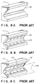
- FIG. 7 showing the prior art leading edge structure 100 for an aircraft disclosed in JP-A-9-71298 in a partially cutaway perspective view
- an inner skin 102 of a fiber-reinforced plastic and a front wall 103 are disposed on the inner side of an outer skin 101 of a fiber-reinforced plastic.
- the outer skin 101, the inner skin 102 and the front wall 103 are united by bonding to define a heating chamber 104 in the leading edge structure 100.
- a rear wall 105 is disposed behind the front wall 103 to define a hot air discharge chamber 106 between the front wall 103 and the rear wall 105.
- the heating chamber 104 is partitioned by the front wall 103 into a hot air jetting section 104a on the front side and a hot air passage section 104b on the rear side.
- An anti-icing duct 108 provided with a plurality of air jetting holes 108a is extended in the hot air jetting section 104a.
- Hot air flows through the anti-icing duct 108.
- Hot air ejected through the hot air jetting holes 108a of the anti-icing duct 108 flows from the hot air jetting section 104a into the hot air passage section 104b, flows along hot air passages 104c formed in the hot air passage section 140b into the hot air discharge chamber 106, and is discharged through a discharge hole formed in the tip of the wing into the atmosphere.
- the formation of ice on the leading edge structure 100 is prevented by thus making the hot air flow along the inner surface of the outer skin 101 of the leading edge structure 100.
- an outer skin prepreg sheet 112 for forming the outer skin 101 is placed on a shaping surface of a leading edge skin mold 111 having a shape corresponding to the external shape of the outer skin 101.
- a comb-shaped silicone block 113 is placed as shown in Fig. 8B on the inner surface of the outer skin prepreg sheet 112 before hardening.
- An inner skin prepreg sheet 114 for forming the inner skin 102 is placed on the silicone block 113 so that parts thereof are forced into spaces between adjacent teeth to form straightening fins defining the hot air passages 104c.
- the leading edge skin mold 111 holding the outer skin prepreg sheet 112, the silicone block 113 and the inner skin prepreg sheet 114 is placed in a vacuum bag, and the vacuum bag is evacuated, the outer skin prepreg sheet 112 and the inner skin prepreg sheet 114 are heated and compressed to unite the outer skin prepreg sheet 112 and the inner skin prepreg sheet 114 by bonding the straightening fins of the inner skin prepreg sheet 114 to the outer skin prepreg sheet 112. Subsequently, the silicone block 113 is removed, the front wall 103 formed by a separate process is joined to the assembly of the outer skin prepreg sheet 112 and the inner skin prepreg sheet 114 (Fig. 8C), and the anti-icing duct 108 is attached to the front wall 103 to complete the leading edge structure 100.
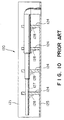
- Figs. 9 is a perspective view of an aluminum alloy leading edge structure 120
- Fig. 10 is a sectional view taken on line X-X in Fig. 9
- Fig. 11 is a sectional view taken on line X1-X1 in Fig. 9.
- the aluminum alloy leading edge structure 120 will be described with reference to Figs. 9, 10 and 11.
- An inner skin 122 formed by bending a corrugated sheet is extended along the inner surface of an outer skin 121 to form a hot air passage 123 extending along the inner surface of the outer skin 121 structure.
- a hot air outlet opening 122a is formed in a part of the inner skin 122 corresponding to the front edge of the leading edge structure 120.
- a plurality of ribs 124 are attached to the inner skin 124 to divide a space defined by the inner skin 122 into a plurality of sections.
- a front wall 125 are attached to the rear edges of the inner skin 124.
- Each rib 124 is provided with an opening 124a.
- An anti-icing duct 127 is extended through the openings 124a of the ribs 124, and the anti-icing duct 127 is fastened to the ribs 124 by clips 128 formed by bending a sheet. As shown in Fig. 12 in a perspective view, the anti-icing duct 127 is provided with a plurality of air outlet openings 127a.
- Hot air of a high temperature supplied into the anti-icing duct 127 is jetted through the air outlet openings 127a into the space defined by the inner skin 122 and the front wall 125. Then, the hot bleed air flows through the hot air outlet opening 122a formed in the inner skin 122 into the space between the outer skin 121 and the inner skin 122, flows through the same space along the inner surface of the outer skin 121 and is discharged through a discharge hole formed in the tip of the wing into the atmosphere.
- the hot air that flows along the inner surface of the outer skin structure 121 raises the surface temperature of the outer skin 121 to prevent the formation of ice on the surface of the leading edge structure 120.
- the outer skin 121, the inner skin 122 and the rib 124 of the leading edge structure 120 are built by forming aluminum alloy sheets by press forming or roll forming, and finished by shaping the external shape by trimming.
- the clips 128 for fastening the anti-icing duct 127 to the ribs 124 are formed by bending an aluminum alloy sheet.
- the anti-icing duct 127 is formed by bending a tube of a titanium alloy or a stainless steel, and forming the plurality of air outlet openings 127a in the tube.
- the leading edge structure 120 is constructed by positioning these components of the leading edge structure 120 relative to each other by using jigs and adjusting shims, forming holes for receiving fasteners in the components, and fastening together the components with fastening means, such as rivets and clips.
- the leading edge structure is formed by bonding together and hardening the outer skin 101 of a fiber-reinforced plastic, the inner skin 102 of a fiber-reinforced plastic, and the front wall 103. Therefore, firm joints are formed between the outer skin 101 and the inner skin 102 by its own adhesive strength of the outer skin 101 and the inner skin 102.
- the leading edge structure 100 cannot be formed in a required strength.
- leading edge structure 100 needs many processes and troublesome work because the leading edge structure 100 is fabricated by placing the outer skin prepreg sheet 112 for forming the outer skin 101 on the shaping surface of the leading edge skin mold 111 having a shape corresponding to the external shape of the outer skin 101, placing the comb-shaped silicone block 113 on the inner surface of the outer skin prepreg sheet 112, placing the inner skin prepreg sheet 114 for forming the inner skin 102 on the silicone block 113, placing the leading edge skin tool mold 111 holding the outer skin prepreg sheet 112, the silicone block 113 and the inner skin prepreg sheet 114 in the vacuum bag, evacuating the vacuum bag, heating and compressing the outer skin prepreg sheet 112 and the inner skin prepreg sheet 114 to unite and harden the outer skin prepreg sheet 112 and the inner skin prepreg sheet 114 , removing the silicone block 113, joining the front wall 103 formed by a separate process to the assembly of the outer skin prepreg sheet 112 and the inner skin prepreg sheet
- the outer skin 121, the inner skin structure, the plurality of ribs 124, the anti-icing duct 127 and the plurality of clips 128 respectively having different shapes need to be assembled when fabricating the latter prior art leading edge structure 120.
- Those components need to be formed in high accuracy and need expensive jigs to position the same correctly relative to each other, and the leading edge structure must be formed in an accurate external shape meeting severe aerodynamic requirements.
- the relative positions of the components must be adjusted by using shims, and much labor is required for forming the holes in the components and fastening together the components with fasteners, such as rivets, inserted in the holes.
- the anti-icing duct 127 Since the anti-icing duct 127 must be heat-resistant, the same is made of a titanium alloy or a stainless steel.
- the titanium alloy of the stainless steel are hard to work and hence the formation of the air outlet openings 127a in the anti-icing duct 127 needs the frequent changes of boring tools, troublesome work and much labor.
- Another object of the present invention is to provide a method of fabricating such a leading edge structure.
- a leading edge structure of an airfoil comprises: an outer skin continusously and integrally formed of upper and lower sections; a front wall extending in a spanwise direction of the leading edge structure in a front section of the outer skin; an air hole provided through the front wall; a plurality of ribs disposed between the upper and lower sections of the outer skin so as to form a hot air passage for a hot air supplied through the air hole of the front wall.
- the outer skin, the front wall and the ribs are made of a superplastic alloy, and are formed by superplastic forming.
- the anti-icing duct is formed by closing a front part of the inner space of the leading edge structure
- the hot air passages are formed by partitioning the inner space between the upper and the lower section of the outer skin by the ribs, and the outer skin
- the front wall and the ribs may be formed by constructing the laminar structure by superposing the sheets of a superplastic titanium alloy and bonding together the predetermined parts of the sheets by diffusion bonding or welding, and subjecting the laminar structure to superplastic forming. Therefore the leading edge structure has a high strength, work for mounting an anti-icing duct on the front wall can be omitted, and assembling work is simplified.
- a method of fabricating a leading edge structure of an airfoil according to a second aspect of the present invention comprises: a superposing step for forming a laminar structure by superposing a superplastic alloy upper sheet and a superplastic alloy lower sheet, inserting a pair of superplastic alloy core sheets between the upper and lower sheets, and applying release agent layers between the pair of core sheets in a region corresponding to anti-icing duct, between the upper sheet and one of the core sheets in regions corresponding to hot air passages and between the lower sheet and other core sheet in regions corresponding to the hot air passages; a laminar structure setting step for setting the laminar structure in a mold having a forming surface of a shape corresponding to an external shape of the leading edge structure; a forming step for forming a structure having an outer skin, a front wall and ribs by joining together parts of the superposed sheets corresponding to regions not applied with the release agent layers by diffusion bonding or welding, heating the laminar structure, supplying a superplastic forming gas into
- the leading edge structure comprising the outer skin, the anti-icing duct, the hot air passage and the ribs is thus constructed by properly superposing the core sheets, the upper and the lower sheet with the release agent layers applied in the appropriate regions between the sheets, properly joining together the sheets by diffusion bonding or welding and shaping the sheets by superplastic forming. Accordingly, component members which are necessary for forming the prior art leading edge structure including ribs and the like respectively having different shapes need not be individually fabricated, assembling work for assembling the component members is unnecessary, and many of jigs which are necessary for fabricating the prior art leading edge structure can be omitted.
- the mold may have a first half mold having a forming surface of a shape corresponding to that of an upper section of the outer skin of the leading edge structure, and a second half mold having a forming surface of a shape corresponding to that of a lower section of the outer skin of the leading edge structure, the laminar structure may be disposed between the first and the second half mold in the laminar structure setting step, and the upper and the lower sheet may be pressed against the forming surface of the first half mold and the forming surface of the second half mold, respectively, in the forming step.
- through holes may be formed in parts of the core sheets corresponding to the regions in which the release agent layers are applied to achieve efficient supply of the superplastic forming gas into spaces between corresponding parts of the superposed sheets applied with the release agent layers.
- the through holes may be formed so that the holes serve as air jetting openings formed in the front wall after the superplastic forming gas has been supplied into spaces between corresponding parts of the superposed sheets applied with the release agent layers to subject the same parts of the superposed sheets to superplastic deformation, and the upper sheet and the lower sheet have been pressed against the forming surfaces of the first and the second half mold, respectively.
- boring work for forming holes in the front wall can be omitted and thereby the work for fabricating the leading edge structure can be simplified.
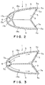
- the leading edge structure 1 has an ice formaiton preventing means wherein a high temperature air from an engine compressor is guided into the interior space of the leading edge structure enclosed by an outer skin 2 so as to flow along the inner surface of the outer skin 2 to raise the surface temperature of the skin 2 in order that the ice formation on the surface of the leading edge structure 1 is prevented.
- the leading edge structure members 1 are made of a superplastic titanium alloy, such as Ti-6Al-4V.
- the outer skin 2 has a substantially U-shaped cross section and integrally consists of an upper section 3 and a lower section 4.
- a rear wall 5 extends between a rear edge 3a of the upper section 3 and a rear edge 4a of the lower section 4.
- the outer skin 2 and the rear wall 5 define a hot air chamber 6.
- a front wall 7 formed integrally with the outer skin 2 extends along the length of the leading edge structure 1 to form an anti-icing duct 8 in a front section of the hot air chamber 6 together with a front end part of the outer skin 2.
- Honeycomb ribs 9 having a polygonal cross section are formed between the upper section 3 and the lower section 4 of the outer skin 2 so as to extend between the front wall 7 and the rear wall 5 to form a plurality of hot air passages 10 extending in the direction of the width of the wing.
- the front wall 7 separating the anti-icing duct 8 from the hot air passages 10 is provided with a plurality of air jetting holes 7a to eject hot air from the anti-icing duct 8 into the hot air passages 10.
- Superplastic forming is used to form the component members of the leading edge structure 1 including the upper section 3 of the outer skin 2, the lower section 4 of the outer skin 2, the rear wall 5, the front wall 7 and the ribs 9 defining the hot air chamber 6, the anti-icing duct 8 and the hot air passages 10.
- diffusion bonding is used to form the joint 12a of the sections 3 and 4 of the outer skin 2, the joint 15a of the rear edge 3a of the upper section 3 of the outer skin 2 and the rear wall 5, the joint 15a of the rear edge 4a of the lower section 4 of the outer skin 2, the joint 17a of the upper section 3 of the outer skin 2 and the front wall 7, the joint 17a of the lower section 4 of the outer skin 2, the joints 19a of the upper section 3 of the outer skin 2 and the ribs 9, and the joints 19b of the lower section 4 of the outer skin and the ribs 9.
- High temperature air supplied into the anti-icing duct 8 is supplied through the air jetting holes 7a formed in the front wall 7 into the hot air passages 10 defined by the upper section 3 of the outer skin 2 and the ribs 9, and into the hot air passages 10 defined by the lower section 4 of the outer skin 2 and the ribs 9. Then the hot bleed air flows along the inner surfaces of the upper section 3 and the lower section 4 of the outer skin 2 and is discharged through air outlet holes 5a formed in the rear wall 5 and through a discharge hole formed in the tip of the wing into the atmosphere.
- the hot air supplied into the anti-icing duct 8 and flowing along the inner surfaces of the upper section 3 and the lower section 4 of the outer skin 2 raises the surface temperature of the outer skin 2 to prevent the ice formation on the front surface of the wing.
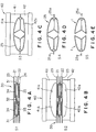
- a method of fabricating the leading edge structure 1 will be described with reference to Figs. 4A to 4E.
- Preparation is made of four superplastic titanium alloy sheets of, for example, Ti-6Al-4V, i.e., a pair of core sheets 21 and 22 for forming the anti-icing duct 8, the ribs 9 and the rear wall 5, an upper sheet 23 for forming the upper section 3 of the outer skin 2 and a lower sheet 24 for forming the lower section 4 of the outer skin 2.
- the sheets 21, 22, 23 and 24 have sizes sufficient to form the two leading edge structures 1 for the right and the left wing simultaneously and symmetrically in a united structure.
- the two leading edge structures 1 are formed in the united structure and the united structure is divided into the two leading edge structures 1.
- a forming device 40 employed in fabricating the leading edge structure 1 is provided with a mold having a first half mold 41 and a second half mold 42.
- the first half mold 41 and the second half mold 42 have generally concave forming surfaces 41a and 42a, respectively.
- the first half mold 41 and the second half mold 42 are disposed with the respective forming surfaces 41a and 42a thereof facing each other.
- the forming surface 41a of the first half mold 41 corresponds to the upper surface of a united structure formed by bonding together the rear edges 3a of the upper sections 3 of the pair of leading edge structures 1 for a wing and by bonding together the rear edges 4a of the lower sections 4 of the same pair of leading edge structures 1.
- the forming surface 42a of the second half mold 42 corresponds to the lower surface of the same united structure.
- the forming surfaces 41a and 42a form a closed surface of a shape corresponding to the external shape of the united structure.
- elongate longitudinal release agent layers 31 of a predetermined width are formed between the pair of core sheets 21 and 22 along the opposite end edges of the pair of core sheets 21 and 22 in regions corresponding to the anti-icing ducts 8 of the pair of leading edge structures 1 to be formed simultaneously.
- An elongate middle longitudinal release agent layer 32 of a predetermined width is formed between the pair of core sheets 21 and 22 in a region corresponding to the rear walls 5 of the pair of leading edge structures 1.
- a plurality of transverse release agent layers 33 are formed between the longitudinal release agent layers 31 and the middle longitudinal release agent layer 32.
- Transverse release agent layers 34 are formed between the core sheet 21 and the upper sheet 23 in regions excluding those corresponding to the joints 19a of the upper sections 3 of the outer skins 2 and the ribs 9, i.e., in regions corresponding to the hot air passages 10.
- the transverse release agent layers 34 formed between the core sheet 21 and the upper sheet 23 in regions corresponding to the hot air passages 10 partly overlap the release agent layers 31, 32 and 33 formed between the core sheets 21 and 22 as shown in Fig. 5.
- many through holes 21a which serve as the air jetting holes 7a, are formed in the core sheet 21 at positions in regions where the longitudinal release agent layers 31 and the transverse release agent layers 34 overlap each other.
- Through holes 21b which serve as the air outlet holes 5a, are formed in the core sheet 21 at positions in regions where the middle longitudinal release agent layer 32 and the transverse release agent layers 34 overlap each other.
- Through holes 21c are formed in the core sheet 21 at positions in regions where the transverse release agent layers 33 and 34 overlap each other to enable a space between the upper sheet 23 and the core sheet 21 and a space between the core sheets 21 and 22 communicate with each other.
- Transverse release agent layers 35 are formed between the core sheet 22 and the lower sheet 24 in regions excluding those corresponding to the joints 19b of the lower sections 4 of the outer skins 2 and the ribs 9, i.e., in regions corresponding to the hot air passages 10.
- the transverse release agent layers 35 formed between the core sheet 22 and the lower sheet 24 in regions corresponding to the hot air passages 10 partly overlap the release agent layers 31, 32 and 33 formed between the core sheets 21 and 22 as shown in Fig. 6.
- Through holes 22a which serve as the air jetting holes 7a, are formed in the core sheet 22 at positions in regions where the longitudinal release agent layers 31 and the transverse release agent layers 35 overlap each other.
- Through holes 22b which serve as the air outlet holes 5a, are formed in the core sheet 22 at positions in regions where the middle longitudinal release agent layer 32 and the transverse release agent layers 35 overlap each other.
- Through holes 22c are formed in the core sheet 22 at positions in regions where the transverse release agent layers 33 and 35 overlap each other.
- the core sheets 21 and 22, the upper sheet 23 and the lower sheet 24 provided with the release agent layers 31, 32, 33, 34 and 35 are superposed to construct a laminar structure 20 as shown in Fig. 4A and Fig. 6.
- the laminar structure 20 thus constructed in the superposing process S1 is positioned on the second half mold 42 of the forming device 40 as shown, and the laminar structure 20 is clamped between the first half mold 41 and the second half mold 42.
- the forming device 40 holding the laminar structure 20 between the first half mold 41 and the second half mold 42 is carried into a heating furnace, not shown.
- a superplastic forming gas i.e., an inert gas, such as argon or helium gas, of a predetermined pressure is supplied through a gas inlet port, not shown, formed in the forming device 40 into a cavity 41A (Fig.
- the cavities 41A and 42A are evacuated, and then a superplastic forming gas of a pressure in the range of 10 to 30 kgf/cm 2 is forced into spaces between parts of the core sheets 21 and 22 corresponding to the longitudinal release agent layers 31. Consequently, the parts of the core sheets 21 and 22 corresponding to the release agent layers 31, i.e., parts of the core sheets 21 and 22 for forming the anti-icing ducts 8, are subjected to superplastic deformation.
- the superplastic forming gas further flows through the through holes 21a and 22a of the core sheets 21 and 22 into spaces between parts of the core sheet 21 and the upper sheet 23 corresponding to the transverse release agent layers 34 and into spaces between parts of the core sheet 22 and the lower sheet 24 corresponding to the transverse release agent layers 35. Consequently, the parts of the core sheets 21 and 22, the upper sheet 23 and the lower sheet 24 corresponding to the transverse release agent layers 34 and 35, i.e., parts mainly for forming the hot air passages 10, are subjected to superplastic deformation.
- the superplastic forming gas flows also through the through holes 21c and 22c into space between parts of the core sheets 21 and 22 corresponding to the transverse release agent layers 33. Consequently, the parts of the core sheets 21 and 22 are subjected to superplastic deformation to form mainly the ribs 9.
- the superplastic forming gas flows through the through holes 21b and 22b into spaces between parts of the core sheets 21 and 22 corresponding to the middle longitudinal release agent layer 32, so that the same parts of the core sheets 21 and 22 are subjected to superplastic deformation to form the rear walls 5.
- the parts of the core sheets 21 and 22, the upper sheet 23 and the lower sheet 24 corresponding to the release agent layers 31, 32, 33, 34 and 35 are subjected to the superplastic deforming action of the superplastic forming gas.
- the superplastic forming gas is supplied continuously until the upper sheet 23 is pressed perfectly against the forming surface 41a of the first half mold 41, and the, lower sheet 24 is pressed perfectly against the forming surface 42a of the second half mold 42 as shown in Fig. 4C to complete a united structure 25.
- a trimming process S5 shown in Fig. 4E flanges 25a projecting from the periphery of the united structure 25 are removed, the united structure 25 is divided along the center axis into a pair of symmetrical structures, and the symmetrical structures are trimmed by grinding or the like to finish a pair of leading edge structures 1 respectively for the right and the left wing as shown in Figs. 1, 2 and 3.
- the outer skin 2 and the rear wall 5 define the hot air chamber 6, a front section of the hot air chamber 6 is closed by the front wall 7 to form the longitudinal anti-icing duct 8, the ribs 9 extend between the upper section 3 and the lower section 4 of the outer skin 2 from the front wall 7 to the rear wall 5. Since the component sheets 21, 22, 23 and 24 are united in an integral unit by diffusion bonding, the leading edge structure 1 has a high strength.
- the leading edge structure 1 having the anti-icing duct 8, the ribs 9 and the hot air passages 10 is formed by constructing the laminar structure 20 by superposing the core sheets 21 and 22, the upper sheet 23 and the lower sheet 24, by forming the release agent layers 31, 32, 33, 34 and 35 in appropriate regions between the core sheets 21 and 22, the upper sheet 23 and the lower sheet 24, and by subjecting the laminar structure 20 to the diffusion bonding process and the superplastic forming process. Accordingly, many component members with different shapes such as ribs as those of the prior art need not be individually fabricated, assembling work for assembling the component members is unnecessary, and many of jigs which are necessary for fabricating the prior art leading edge structure can be omitted. Since the through holes 21a and 22a used in the superplastic forming process serve as the air jetting holes 7a, the boring work for forming holes in the wall of the anti-icing duct 8 is unnecessary, which simplifies the work for fabricating the leading edge structure 1.
- the parts of the core sheets 21 and 22, the upper sheet 23 and the lower sheet 24 to be bonded together may be bonded by welding instead of diffusion bonding.
- a liquid-interface diffusion bonding which forms an insert layer, such as a Cu-Ni plated layer, between necessary portions of the sheets to be bonded together, may be employed in bonding the portions of the core sheets 21 and 22, the upper sheet 23 and the lower sheet 24 to be bonded together.
- the laminar structure may be provided with additional core sheets to form ribs different from those of the foregoing embodiment and necessary for forming a leading edge structure of a required strength.
- Sheets of a release agent may be used instead of the release agent layers.
- a front section of the internal space defined by the outer skin and the rear wall is closed by the front wall to form the anti-icing duct, and the ribs are formed between the upper and the lower section of the outer skin to form the hot air passages through which hot air flows along the inner surfaces of the outer skin.
- parts not coated with the release agent layers of the component members of a superplastic titanium alloy of the leading edge structure including the outer skin, the front wall and the ribs are bonded together by diffusion bonding or welding, and parts coated with the release agent layers of the component members are formed in desired shapes by the superplastic forming process to form the leading edge structure. Therefore, the leading edge structure has a high strength, any work for attaching an anti-icing duct to the leading edge structure is unnecessary and work for fabricating the leading edge structure is simplified.
- the method of fabricating the leading edge structure for an aircraft airfoil of the present invention forms the leading edge structure integrally provided with the anti-icing duct, the hot air passages and the ribs by constructing the laminar structure by superposing the core sheets, the upper sheet and the lower sheet and forming the release agent layers in appropriate regions between the sheets, bonding together the predetermined parts of the sheets by diffusion bonding or welding, and deforming the parts corresponding to the release agent layers of the sheets by superplastic forming. Therefore, many component members, such as ribs, of different shapes, and many of the jigs necessary for making and assembling the component members can be omitted.
- the superplastic forming gas can be efficiently supplied into the spaces between the parts of the sheets to be deformed.
Landscapes
- Engineering & Computer Science (AREA)
- Aviation & Aerospace Engineering (AREA)
- Mechanical Engineering (AREA)
- Manufacturing & Machinery (AREA)
- Physics & Mathematics (AREA)
- Fluid Mechanics (AREA)
- Transportation (AREA)
- Pressure Welding/Diffusion-Bonding (AREA)
- Shaping Metal By Deep-Drawing, Or The Like (AREA)
Applications Claiming Priority (3)
| Application Number | Priority Date | Filing Date | Title |
|---|---|---|---|
| JP19858497 | 1997-07-24 | ||
| JP19858497A JP3647612B2 (ja) | 1997-07-24 | 1997-07-24 | 航空機の前縁構造及びその製造方法 |
| JP198584/97 | 1997-07-24 |
Publications (3)
| Publication Number | Publication Date |
|---|---|
| EP0893342A2 true EP0893342A2 (fr) | 1999-01-27 |
| EP0893342A3 EP0893342A3 (fr) | 2001-03-21 |
| EP0893342B1 EP0893342B1 (fr) | 2004-09-29 |
Family
ID=16393615
Family Applications (1)
| Application Number | Title | Priority Date | Filing Date |
|---|---|---|---|
| EP98113713A Expired - Lifetime EP0893342B1 (fr) | 1997-07-24 | 1998-07-22 | Structure de bord d'attaque pour une surface aérodynamique et procédé pour sa fabrication |
Country Status (4)
| Country | Link |
|---|---|
| US (2) | US6119978A (fr) |
| EP (1) | EP0893342B1 (fr) |
| JP (1) | JP3647612B2 (fr) |
| DE (1) | DE69826576T2 (fr) |
Cited By (10)
| Publication number | Priority date | Publication date | Assignee | Title |
|---|---|---|---|---|
| EP1103462A1 (fr) * | 1999-11-23 | 2001-05-30 | The Boeing Company | Procédé et dispositif de protection contre le givre dans l'entrée d'air d'un avion |
| EP1327489A1 (fr) | 2002-01-11 | 2003-07-16 | Sonaca S.A. | Procédé de fabrication d'une structure cannelée et structure obtenue par ce procédé |
| US6688558B2 (en) | 1999-11-23 | 2004-02-10 | The Boeing Company | Method and apparatus for aircraft inlet ice protection |
| FR2867096A1 (fr) * | 2004-03-08 | 2005-09-09 | Snecma Moteurs | Procede de fabrication d'un bord d'attaque ou de fuite de renforcement pour une aube de soufflante |
| GB2440133A (en) * | 2006-07-18 | 2008-01-23 | Gkn Aerospace Transparency Sys | A de-icing heated leading edge component of an aircraft |
| US7965201B2 (en) | 2003-04-16 | 2011-06-21 | The Boeing Company | Method and apparatus for detecting conditions conducive to ice formation |
| FR2975929A1 (fr) * | 2011-06-01 | 2012-12-07 | Airbus Operations Sas | Procede de fabrication de la structure du bord d'attaque d'une surface aerodynamique |
| CN106881561A (zh) * | 2015-12-15 | 2017-06-23 | 航天特种材料及工艺技术研究所 | 一种钛合金薄壁多层中空结构的制备方法 |
| IT201600098196A1 (it) * | 2016-09-30 | 2018-03-30 | Torino Politecnico | Aeromobile dotato di sistema antighiaccio strutturalmente integrato. |
| US11247766B2 (en) | 2011-12-01 | 2022-02-15 | Airbus Operations Limited | Leading edge structure |
Families Citing this family (32)
| Publication number | Priority date | Publication date | Assignee | Title |
|---|---|---|---|---|
| US6702233B1 (en) * | 2001-02-07 | 2004-03-09 | Rohr, Inc. | Airfoil anti-icing assembly and method |
| ES2205961B2 (es) * | 2001-02-13 | 2005-03-01 | Eads Construcciones Aeronauticas, S.A. | Procedimiento de fabricacion de elementos de material compuesto mediante la tecnoclogia del coencolado. |
| JP4541576B2 (ja) * | 2001-02-26 | 2010-09-08 | 富士重工業株式会社 | 超塑性金属の一体成形方法 |
| BE1014254A3 (fr) * | 2001-06-20 | 2003-07-01 | Sonaca Sa | Structure tubulaire mince cloisonnee et son procede de fabrication. |
| DE10346982A1 (de) * | 2003-10-09 | 2005-05-04 | Airbus Gmbh | Tragwerk-Profilstruktur eines Flugzeuges |
| US6913064B2 (en) * | 2003-10-15 | 2005-07-05 | United Technologies Corporation | Refractory metal core |
| DE102004001666A1 (de) * | 2004-01-12 | 2005-08-04 | Mtu Aero Engines Gmbh | Verfahren zur Herstellung von Hohlschaufeln |
| US7210611B2 (en) | 2004-10-21 | 2007-05-01 | The Boeing Company | Formed structural assembly and associated preform and method |
| US7431196B2 (en) * | 2005-03-21 | 2008-10-07 | The Boeing Company | Method and apparatus for forming complex contour structural assemblies |
| FR2906320B1 (fr) * | 2006-09-26 | 2008-12-26 | Snecma Sa | Aube composite de turbomachine a renfort metallique |
| US7871041B2 (en) * | 2007-10-17 | 2011-01-18 | Lockheed Martin Corporation | System, method, and apparatus for leading edge structures and direct manufacturing thereof |
| US8123167B2 (en) * | 2008-12-15 | 2012-02-28 | Embraer S.A. | Impact resistant aircraft leading edge structures and aircraft including the same |
| US8061657B2 (en) | 2008-12-31 | 2011-11-22 | General Electric Company | Method and apparatus for aircraft anti-icing |
| GB0903281D0 (en) * | 2009-02-27 | 2009-04-08 | Rolls Royce Plc | Method of manufacturing a blade |
| GB0903280D0 (en) * | 2009-02-27 | 2009-04-08 | Rolls Royce Plc | Method of manufacturing a blade |
| JP4402160B1 (ja) * | 2009-03-02 | 2010-01-20 | 山田 正明 | 模型回転翼航空機の回転翼、及びその回転翼の製造方法 |
| GB2470043B (en) * | 2009-05-06 | 2011-06-08 | Gkn Aerospace Services Ltd | Heating system |
| GB0913061D0 (en) * | 2009-07-28 | 2009-09-02 | Rolls Royce Plc | A method of manufacturing a reinforcing edge for a turbo machine aerofoil |
| FR2954279B1 (fr) * | 2009-12-18 | 2014-08-22 | Airbus Operations Sas | Entree d'air d'une nacelle d'aeronef integrant des moyens d'injection en air chaud pour le traitement du givre optimises |
| JP2011183922A (ja) | 2010-03-08 | 2011-09-22 | Mitsubishi Heavy Ind Ltd | 航空機における翼前縁部の防除氷装置及び航空機主翼 |
| US10556670B2 (en) * | 2010-08-15 | 2020-02-11 | The Boeing Company | Laminar flow panel |
| JP5582927B2 (ja) | 2010-08-30 | 2014-09-03 | 三菱重工業株式会社 | 航空機の防除氷システム及びこれを備える航空機 |
| CN102996510A (zh) * | 2011-09-15 | 2013-03-27 | 中航商用航空发动机有限责任公司 | 空心叶片 |
| GB2533115A (en) | 2014-12-09 | 2016-06-15 | Airbusgroup Ltd | Aircraft wing rib |
| JP6666159B2 (ja) | 2016-01-21 | 2020-03-13 | 三菱航空機株式会社 | 防氷装置、及び、航空機 |
| JP2017136893A (ja) * | 2016-02-01 | 2017-08-10 | 三菱航空機株式会社 | 防氷装置、及び、航空機 |
| JP6839920B2 (ja) * | 2016-02-12 | 2021-03-10 | 三菱航空機株式会社 | 防氷装置、及び、航空機 |
| US20170314412A1 (en) * | 2016-05-02 | 2017-11-02 | General Electric Company | Dimpled Naccelle Inner Surface for Heat Transfer Improvement |
| US11156099B2 (en) * | 2017-03-28 | 2021-10-26 | General Electric Company | Turbine engine airfoil with a modified leading edge |
| DE102017130884B4 (de) * | 2017-12-21 | 2019-08-14 | Airbus Defence and Space GmbH | Luftfahrzeug und Verfahren zum Herstellen eines Luftfahrzeugs |
| FR3091263A1 (fr) * | 2018-12-28 | 2020-07-03 | Daher Aerospace | Bec de bord d’attaque à structure optimisée |
| EP4074602A1 (fr) * | 2021-04-13 | 2022-10-19 | Airbus Operations GmbH | Tube piccolo de dégivrage d'une structure de surface portante d'un aéronef, système de dégivrage et structure de surface portante |
Citations (1)
| Publication number | Priority date | Publication date | Assignee | Title |
|---|---|---|---|---|
| JPH0971298A (ja) | 1995-09-05 | 1997-03-18 | Honda Motor Co Ltd | 航空機の前縁構造及びその製造方法 |
Family Cites Families (6)
| Publication number | Priority date | Publication date | Assignee | Title |
|---|---|---|---|---|
| US4738416A (en) * | 1986-09-26 | 1988-04-19 | Quiet Nacelle Corporation | Nacelle anti-icing system |
| US5011098A (en) * | 1988-12-30 | 1991-04-30 | The Boeing Company | Thermal anti-icing system for aircraft |
| US5330092A (en) * | 1991-12-17 | 1994-07-19 | The Boeing Company | Multiple density sandwich structures and method of fabrication |
| FR2724127B1 (fr) * | 1994-09-07 | 1996-12-20 | Snecma | Procede de fabrication d'une aube creuse de turbomachine |
| FR2739832B1 (fr) * | 1995-10-12 | 1997-12-26 | Aerospatiale | Structure metallique creuse monobloc et dissymetrique telle qu'un bord de fuite d'un bec d'attaque d'une voilure d'aeronef et son procede de fabrication |
| FR2749784B1 (fr) * | 1996-06-13 | 1998-07-31 | Snecma | Procede de fabrication d'un aube creuse de turbomachine et presse-four a multiple effet utilisee dans sa mise en oeuvre |
-
1997
- 1997-07-24 JP JP19858497A patent/JP3647612B2/ja not_active Expired - Fee Related
-
1998
- 1998-07-20 US US09/118,870 patent/US6119978A/en not_active Expired - Lifetime
- 1998-07-22 DE DE69826576T patent/DE69826576T2/de not_active Expired - Lifetime
- 1998-07-22 EP EP98113713A patent/EP0893342B1/fr not_active Expired - Lifetime
-
2000
- 2000-08-08 US US09/634,986 patent/US6279228B1/en not_active Expired - Lifetime
Patent Citations (1)
| Publication number | Priority date | Publication date | Assignee | Title |
|---|---|---|---|---|
| JPH0971298A (ja) | 1995-09-05 | 1997-03-18 | Honda Motor Co Ltd | 航空機の前縁構造及びその製造方法 |
Cited By (21)
| Publication number | Priority date | Publication date | Assignee | Title |
|---|---|---|---|---|
| US6371411B1 (en) | 1999-11-23 | 2002-04-16 | The Boeing Company | Method and apparatus for aircraft inlet ice protection |
| US6457676B1 (en) | 1999-11-23 | 2002-10-01 | The Boeing Company | Method and apparatus for aircraft inlet ice protection |
| US6688558B2 (en) | 1999-11-23 | 2004-02-10 | The Boeing Company | Method and apparatus for aircraft inlet ice protection |
| EP1103462A1 (fr) * | 1999-11-23 | 2001-05-30 | The Boeing Company | Procédé et dispositif de protection contre le givre dans l'entrée d'air d'un avion |
| EP1327489A1 (fr) | 2002-01-11 | 2003-07-16 | Sonaca S.A. | Procédé de fabrication d'une structure cannelée et structure obtenue par ce procédé |
| BE1014570A4 (fr) * | 2002-01-11 | 2004-01-13 | Sonaca Sa | Procede de fabrication d'une structure cannelee et structure obtenue par ce procede. |
| US6739029B2 (en) | 2002-01-11 | 2004-05-25 | Sonaca S.A. | Manufacturing process for a grooved structure and structure obtained by this process |
| US7965201B2 (en) | 2003-04-16 | 2011-06-21 | The Boeing Company | Method and apparatus for detecting conditions conducive to ice formation |
| US7640661B2 (en) | 2004-03-08 | 2010-01-05 | Snecma | Process for manufacturing a reinforcing leading or trailing edge for a fan blade |
| FR2867096A1 (fr) * | 2004-03-08 | 2005-09-09 | Snecma Moteurs | Procede de fabrication d'un bord d'attaque ou de fuite de renforcement pour une aube de soufflante |
| EP1574270A1 (fr) * | 2004-03-08 | 2005-09-14 | Snecma Moteurs | Procédé de fabrication d'un bord d'attaque ou de fuite de renforcement pour une aube de soufflante |
| WO2008009921A1 (fr) * | 2006-07-18 | 2008-01-24 | Gkn Aerospace Services Limited | Structure d'aéronef |
| GB2440133A (en) * | 2006-07-18 | 2008-01-23 | Gkn Aerospace Transparency Sys | A de-icing heated leading edge component of an aircraft |
| US8302911B2 (en) | 2006-07-18 | 2012-11-06 | Gkn Aerospace Services Limited | Aircraft structure |
| FR2975929A1 (fr) * | 2011-06-01 | 2012-12-07 | Airbus Operations Sas | Procede de fabrication de la structure du bord d'attaque d'une surface aerodynamique |
| US11247766B2 (en) | 2011-12-01 | 2022-02-15 | Airbus Operations Limited | Leading edge structure |
| CN106881561A (zh) * | 2015-12-15 | 2017-06-23 | 航天特种材料及工艺技术研究所 | 一种钛合金薄壁多层中空结构的制备方法 |
| IT201600098196A1 (it) * | 2016-09-30 | 2018-03-30 | Torino Politecnico | Aeromobile dotato di sistema antighiaccio strutturalmente integrato. |
| WO2018060808A1 (fr) * | 2016-09-30 | 2018-04-05 | Politecnico Di Torino | Aéronef équipé d'un système de dégivrage structuralement intégré |
| CN110087994A (zh) * | 2016-09-30 | 2019-08-02 | 都灵理工学院 | 配备有结构上集成的除冰系统的飞机 |
| US12091177B2 (en) | 2016-09-30 | 2024-09-17 | Politecnico Di Torino | Aircraft equipped with a structurally integrated de-icing system |
Also Published As
| Publication number | Publication date |
|---|---|
| US6119978A (en) | 2000-09-19 |
| JP3647612B2 (ja) | 2005-05-18 |
| US6279228B1 (en) | 2001-08-28 |
| EP0893342A3 (fr) | 2001-03-21 |
| JPH1134993A (ja) | 1999-02-09 |
| EP0893342B1 (fr) | 2004-09-29 |
| DE69826576T2 (de) | 2005-11-17 |
| DE69826576D1 (de) | 2004-11-04 |
Similar Documents
| Publication | Publication Date | Title |
|---|---|---|
| US6119978A (en) | Leading edge structure of aircraft airfoil and method of fabricating the same | |
| US5692881A (en) | Hollow metallic structure and method of manufacture | |
| US5253419A (en) | Method of manufacturing a hollow blade for a turboshaft engine | |
| US6739029B2 (en) | Manufacturing process for a grooved structure and structure obtained by this process | |
| US5330092A (en) | Multiple density sandwich structures and method of fabrication | |
| JP3090324B2 (ja) | 多孔構造物およびその製作方法 | |
| US4549685A (en) | Method for superplastic forming and diffusion bonding Y shaped support structures | |
| RU2585147C2 (ru) | Способ изготовления металлического элемента усиления | |
| JP5235672B2 (ja) | チタニウム組立品の超塑性成形方法及びそれによって製造された航空機の構造 | |
| US5687900A (en) | Structural panel having a predetermined shape and an associated method for superplastically forming and diffusion bonding the structural panel | |
| US5243758A (en) | Design and processing method for manufacturing hollow airfoils (three-piece concept) | |
| US4294419A (en) | Airframe assembly and process | |
| EP0923425B1 (fr) | Formage superplastique d'un element de structure | |
| US4526312A (en) | Low cost method of making superplastically formed and diffusion bonded structures | |
| CN109207890B (zh) | 一种薄壁spf/db空心结构的热处理方法 | |
| WO1998007547A9 (fr) | Formage superplastique d'un element de structure | |
| US4801070A (en) | Engine duct and case construction | |
| EP1605135B1 (fr) | Méthode de fabrication et assemblage d'une aube de turbine et son pied | |
| US5975465A (en) | Asymmetrical, one-piece, hollow metal structure such as a trailing edge of an aircraft wing leading edge slat and its production process | |
| US6039239A (en) | Method of manufacturing structural parts, particularly for use in aircraft | |
| JP4541576B2 (ja) | 超塑性金属の一体成形方法 | |
| JP4412754B2 (ja) | 構造物の一体成形方法 | |
| JP7001391B2 (ja) | モノリシックな取り付け部材を有する多層構造を超塑性成形する方法 | |
| US20230136264A1 (en) | Method of manufacturing tubular hollow profile vehicle frame parts | |
| US20240308005A1 (en) | Method of manufacturing tubular hollow profile vehicle frame parts |
Legal Events
| Date | Code | Title | Description |
|---|---|---|---|
| PUAI | Public reference made under article 153(3) epc to a published international application that has entered the european phase |
Free format text: ORIGINAL CODE: 0009012 |
|
| 17P | Request for examination filed |
Effective date: 19980722 |
|
| AK | Designated contracting states |
Kind code of ref document: A2 Designated state(s): DE GB |
|
| AX | Request for extension of the european patent |
Free format text: AL;LT;LV;MK;RO;SI |
|
| PUAL | Search report despatched |
Free format text: ORIGINAL CODE: 0009013 |
|
| AK | Designated contracting states |
Kind code of ref document: A3 Designated state(s): AT BE CH CY DE DK ES FI FR GB GR IE IT LI LU MC NL PT SE |
|
| AX | Request for extension of the european patent |
Free format text: AL;LT;LV;MK;RO;SI |
|
| AKX | Designation fees paid |
Free format text: DE GB |
|
| 17Q | First examination report despatched |
Effective date: 20020826 |
|
| GRAP | Despatch of communication of intention to grant a patent |
Free format text: ORIGINAL CODE: EPIDOSNIGR1 |
|
| GRAS | Grant fee paid |
Free format text: ORIGINAL CODE: EPIDOSNIGR3 |
|
| GRAA | (expected) grant |
Free format text: ORIGINAL CODE: 0009210 |
|
| AK | Designated contracting states |
Kind code of ref document: B1 Designated state(s): DE GB |
|
| REG | Reference to a national code |
Ref country code: GB Ref legal event code: FG4D |
|
| REF | Corresponds to: |
Ref document number: 69826576 Country of ref document: DE Date of ref document: 20041104 Kind code of ref document: P |
|
| PLBE | No opposition filed within time limit |
Free format text: ORIGINAL CODE: 0009261 |
|
| STAA | Information on the status of an ep patent application or granted ep patent |
Free format text: STATUS: NO OPPOSITION FILED WITHIN TIME LIMIT |
|
| 26N | No opposition filed |
Effective date: 20050630 |
|
| PGFP | Annual fee paid to national office [announced via postgrant information from national office to epo] |
Ref country code: GB Payment date: 20120718 Year of fee payment: 15 |
|
| PGFP | Annual fee paid to national office [announced via postgrant information from national office to epo] |
Ref country code: DE Payment date: 20120718 Year of fee payment: 15 |
|
| GBPC | Gb: european patent ceased through non-payment of renewal fee |
Effective date: 20130722 |
|
| PG25 | Lapsed in a contracting state [announced via postgrant information from national office to epo] |
Ref country code: DE Free format text: LAPSE BECAUSE OF NON-PAYMENT OF DUE FEES Effective date: 20140201 Ref country code: GB Free format text: LAPSE BECAUSE OF NON-PAYMENT OF DUE FEES Effective date: 20130722 |
|
| REG | Reference to a national code |
Ref country code: DE Ref legal event code: R119 Ref document number: 69826576 Country of ref document: DE Effective date: 20140201 |