EP0893290B1 - Steuerungseinrichtung und hydraulischer Zylinder für eine schwenkbare Nutzfahrzeugachse - Google Patents
Steuerungseinrichtung und hydraulischer Zylinder für eine schwenkbare Nutzfahrzeugachse Download PDFInfo
- Publication number
- EP0893290B1 EP0893290B1 EP98113695A EP98113695A EP0893290B1 EP 0893290 B1 EP0893290 B1 EP 0893290B1 EP 98113695 A EP98113695 A EP 98113695A EP 98113695 A EP98113695 A EP 98113695A EP 0893290 B1 EP0893290 B1 EP 0893290B1
- Authority
- EP
- European Patent Office
- Prior art keywords
- piston
- chamber
- rod
- hydraulic
- rear axle
- Prior art date
- Legal status (The legal status is an assumption and is not a legal conclusion. Google has not performed a legal analysis and makes no representation as to the accuracy of the status listed.)
- Expired - Lifetime
Links
Images

Classifications
-
- B—PERFORMING OPERATIONS; TRANSPORTING
- B60—VEHICLES IN GENERAL
- B60G—VEHICLE SUSPENSION ARRANGEMENTS
- B60G17/00—Resilient suspensions having means for adjusting the spring or vibration-damper characteristics, for regulating the distance between a supporting surface and a sprung part of vehicle or for locking suspension during use to meet varying vehicular or surface conditions, e.g. due to speed or load
- B60G17/005—Suspension locking arrangements
-
- B—PERFORMING OPERATIONS; TRANSPORTING
- B60—VEHICLES IN GENERAL
- B60G—VEHICLE SUSPENSION ARRANGEMENTS
- B60G15/00—Resilient suspensions characterised by arrangement, location or type of combined spring and vibration damper, e.g. telescopic type
-
- B—PERFORMING OPERATIONS; TRANSPORTING
- B60—VEHICLES IN GENERAL
- B60G—VEHICLE SUSPENSION ARRANGEMENTS
- B60G9/00—Resilient suspensions of a rigid axle or axle housing for two or more wheels
- B60G9/02—Resilient suspensions of a rigid axle or axle housing for two or more wheels the axle or housing being pivotally mounted on the vehicle, e.g. the pivotal axis being parallel to the longitudinal axis of the vehicle
-
- B—PERFORMING OPERATIONS; TRANSPORTING
- B66—HOISTING; LIFTING; HAULING
- B66F—HOISTING, LIFTING, HAULING OR PUSHING, NOT OTHERWISE PROVIDED FOR, e.g. DEVICES WHICH APPLY A LIFTING OR PUSHING FORCE DIRECTLY TO THE SURFACE OF A LOAD
- B66F9/00—Devices for lifting or lowering bulky or heavy goods for loading or unloading purposes
- B66F9/06—Devices for lifting or lowering bulky or heavy goods for loading or unloading purposes movable, with their loads, on wheels or the like, e.g. fork-lift trucks
- B66F9/075—Constructional features or details
- B66F9/07586—Suspension or mounting of wheels on chassis
-
- F—MECHANICAL ENGINEERING; LIGHTING; HEATING; WEAPONS; BLASTING
- F15—FLUID-PRESSURE ACTUATORS; HYDRAULICS OR PNEUMATICS IN GENERAL
- F15B—SYSTEMS ACTING BY MEANS OF FLUIDS IN GENERAL; FLUID-PRESSURE ACTUATORS, e.g. SERVOMOTORS; DETAILS OF FLUID-PRESSURE SYSTEMS, NOT OTHERWISE PROVIDED FOR
- F15B15/00—Fluid-actuated devices for displacing a member from one position to another; Gearing associated therewith
- F15B15/08—Characterised by the construction of the motor unit
- F15B15/14—Characterised by the construction of the motor unit of the straight-cylinder type
-
- F—MECHANICAL ENGINEERING; LIGHTING; HEATING; WEAPONS; BLASTING
- F16—ENGINEERING ELEMENTS AND UNITS; GENERAL MEASURES FOR PRODUCING AND MAINTAINING EFFECTIVE FUNCTIONING OF MACHINES OR INSTALLATIONS; THERMAL INSULATION IN GENERAL
- F16F—SPRINGS; SHOCK-ABSORBERS; MEANS FOR DAMPING VIBRATION
- F16F9/00—Springs, vibration-dampers, shock-absorbers, or similarly-constructed movement-dampers using a fluid or the equivalent as damping medium
- F16F9/32—Details
- F16F9/3207—Constructional features
-
- B—PERFORMING OPERATIONS; TRANSPORTING
- B60—VEHICLES IN GENERAL
- B60G—VEHICLE SUSPENSION ARRANGEMENTS
- B60G2200/00—Indexing codes relating to suspension types
- B60G2200/30—Rigid axle suspensions
- B60G2200/32—Rigid axle suspensions pivoted
- B60G2200/322—Rigid axle suspensions pivoted with a single pivot point and a straight axle
-
- B—PERFORMING OPERATIONS; TRANSPORTING
- B60—VEHICLES IN GENERAL
- B60G—VEHICLE SUSPENSION ARRANGEMENTS
- B60G2202/00—Indexing codes relating to the type of spring, damper or actuator
- B60G2202/10—Type of spring
- B60G2202/15—Fluid spring
- B60G2202/154—Fluid spring with an accumulator
-
- B—PERFORMING OPERATIONS; TRANSPORTING
- B60—VEHICLES IN GENERAL
- B60G—VEHICLE SUSPENSION ARRANGEMENTS
- B60G2202/00—Indexing codes relating to the type of spring, damper or actuator
- B60G2202/40—Type of actuator
- B60G2202/41—Fluid actuator
- B60G2202/413—Hydraulic actuator
-
- B—PERFORMING OPERATIONS; TRANSPORTING
- B60—VEHICLES IN GENERAL
- B60G—VEHICLE SUSPENSION ARRANGEMENTS
- B60G2202/00—Indexing codes relating to the type of spring, damper or actuator
- B60G2202/40—Type of actuator
- B60G2202/41—Fluid actuator
- B60G2202/414—Fluid actuator using electrohydraulic valves
-
- B—PERFORMING OPERATIONS; TRANSPORTING
- B60—VEHICLES IN GENERAL
- B60G—VEHICLE SUSPENSION ARRANGEMENTS
- B60G2204/00—Indexing codes related to suspensions per se or to auxiliary parts
- B60G2204/40—Auxiliary suspension parts; Adjustment of suspensions
- B60G2204/46—Means for locking the suspension
-
- B—PERFORMING OPERATIONS; TRANSPORTING
- B60—VEHICLES IN GENERAL
- B60G—VEHICLE SUSPENSION ARRANGEMENTS
- B60G2206/00—Indexing codes related to the manufacturing of suspensions: constructional features, the materials used, procedures or tools
- B60G2206/01—Constructional features of suspension elements, e.g. arms, dampers, springs
- B60G2206/40—Constructional features of dampers and/or springs
-
- B—PERFORMING OPERATIONS; TRANSPORTING
- B60—VEHICLES IN GENERAL
- B60G—VEHICLE SUSPENSION ARRANGEMENTS
- B60G2300/00—Indexing codes relating to the type of vehicle
- B60G2300/02—Trucks; Load vehicles
-
- B—PERFORMING OPERATIONS; TRANSPORTING
- B60—VEHICLES IN GENERAL
- B60G—VEHICLE SUSPENSION ARRANGEMENTS
- B60G2300/00—Indexing codes relating to the type of vehicle
- B60G2300/02—Trucks; Load vehicles
- B60G2300/022—Fork lift trucks, Clark
-
- B—PERFORMING OPERATIONS; TRANSPORTING
- B60—VEHICLES IN GENERAL
- B60G—VEHICLE SUSPENSION ARRANGEMENTS
- B60G2400/00—Indexing codes relating to detected, measured or calculated conditions or factors
- B60G2400/20—Speed
- B60G2400/204—Vehicle speed
-
- B—PERFORMING OPERATIONS; TRANSPORTING
- B60—VEHICLES IN GENERAL
- B60G—VEHICLE SUSPENSION ARRANGEMENTS
- B60G2400/00—Indexing codes relating to detected, measured or calculated conditions or factors
- B60G2400/40—Steering conditions
- B60G2400/41—Steering angle
-
- B—PERFORMING OPERATIONS; TRANSPORTING
- B60—VEHICLES IN GENERAL
- B60G—VEHICLE SUSPENSION ARRANGEMENTS
- B60G2400/00—Indexing codes relating to detected, measured or calculated conditions or factors
- B60G2400/60—Load
- B60G2400/61—Load distribution
-
- B—PERFORMING OPERATIONS; TRANSPORTING
- B60—VEHICLES IN GENERAL
- B60G—VEHICLE SUSPENSION ARRANGEMENTS
- B60G2500/00—Indexing codes relating to the regulated action or device
- B60G2500/20—Spring action or springs
-
- B—PERFORMING OPERATIONS; TRANSPORTING
- B60—VEHICLES IN GENERAL
- B60G—VEHICLE SUSPENSION ARRANGEMENTS
- B60G2800/00—Indexing codes relating to the type of movement or to the condition of the vehicle and to the end result to be achieved by the control action
- B60G2800/01—Attitude or posture control
- B60G2800/012—Rolling condition
Definitions
- the present invention relates to hydraulic apparatus used in an industrial vehicle according to the preamble of claim 1.
- a forklift is generally provided with a rear axle beam and a body frame.
- the center of the rear axle beam can be supported such that the rear axle beam is pivotal with respect to the body frame.
- the body frame and the rear axle beam are connected to each other by a hydraulic cylinder.
- JP-U-56-25609 describes a rear axle beam having ends that are each connected to a body frame by a single action hydraulic cylinder.
- Each hydraulic cylinder has a piston and an oil chamber.
- the oil chambers of the hydraulic cylinders are connected with each other by a passage.
- each piston In accordance with the pivotal movement of the rear axle beam relative to the body frame, each piston is moved axially in its associated cylinder. Hydraulic oil flows between the oil chambers through the passage in accordance with the movement of each piston and restricts the pivotal movement of the rear axle beam.
- the pivotal movement of the rear axle beam can be locked by restricting the movement of the pistons.
- An electromagnetic control valve is arranged in the passage to restrict the movement of the pistons by stopping the flow of hydraulic oil in the passage.
- a forklift that restricts pivotal movements of the rear axle beam by employing two single action hydraulic cylinders requires a large number of components, which are installed on the forklift.
- the owner of the present application has proposed to arrange a multiple action hydraulic cylinder on just one end of the rear axle beam to connect the rear axle beam with the body frame.
- the multiple action hydraulic cylinder has a piston, which defines a first oil chamber and a second oil chamber.
- the first and second oil chambers are connected with each other by a passage.
- the piston is moved axially in accordance with the pivotal movements of the rear axle beam. This moves the hydraulic oil between the first and second oil chambers and restrains the pivotal movement of the rear axle beam relative to the body frame.
- the electromagnetic control valve restricts the movement of the piston by stopping the flow of the hydraulic oil in the passage between the first and second oil chambers.
- the pivotal movements of the rear axle beam are also restricted with this structure.
- this type of forklift employs only one cylinder. Therefore, the installation of the hydraulic cylinder is facilitated due to the smaller number of components.
- one end of the piston is connected to a rod, which extends through one of the hydraulic oil chambers.
- the cross sectional area of this chamber, on which pressure is applied is smaller than that of the other hydraulic oil chamber.
- the pressure applied to the piston differs when the piston moves in opposite directions.
- the velocity of the piston differs according to the moving direction.
- the difference in the velocity of the piston permits the forklift to tilt to the right and to the left in different manners such that the operator can feel the difference.
- the volume of oil that flows outward from one oil chamber is not the same as the volume of oil that enters the other oil chamber. It is thus necessary to eliminate the imbalance between the two oil volumes and permit the forklift to tilt to the right and to the left in the same manner.
- a generic hydraulic apparatus used in an industrial vehicle is shown in EP-A-0 454 474, which comprises the features mentioned in the preamble of claim 1 of the application.
- a hydraulic cylinder is interposed between a vehicle frame and an axle swingably coupled to the frame.
- a hydraulic passage connects a first chamber with a second chamber defined by a piston in a cylinder case.
- the piston is movable in accordance with differential pressure in the first chamber and the second chamber and has a first surface defining the first chamber and a second surface defining the second chamber.
- the first surface has an area equal to that of the second surface.
- a cylinder rod selectively extends and retracts in respect with the cylinder case to absorb a swinging motion of the axle.
- the hydraulic passage is selectively opened and closed.
- the piston rod projects from the first surface of the piston, extends through the first chamber and is connected with the axle.
- a guide rod projects from the second surface of the piston and extends through the second chamber.
- the piston rod has a cross section area equal
- JP-A-06 191 251 JP-A-58 183 307 JP-A-58 214 406 and DE-A-42 35 264.
- Fig. 1 shows a schematic rear view of a forklift having a body frame 1 and a rear axle beam 2.
- the rear axle beam 2 is pivotally supported by a central pin 3, which is arranged in a lower portion of the body frame 1.
- a shock absorbing elastic body 4 is provided between the body frame 1 and the rear axle beam 2 to absorb shocks produced by the pivotal movement of the rear axle beam 2.
- a steered wheel 5 is mounted on each end of the rear axle beam 2 and supported such that the wheel 5 can be pivoted to steer the forklift.
- a multiple action hydraulic cylinder 6 is arranged on one end of the rear axle beam 2.
- the hydraulic cylinder 6 connects the rear axle beam 2 to the body frame 1.
- An electromagnetic control valve 7 and an accumulator 8 are arranged on the body frame 1.
- the hydraulic cylinder 6 is connected to the electromagnetic control valve 7 and the accumulator 8 through passages 9a, 9b, 10a, 10b. Therefore, the passages 9a, 9b, 10a, 10b, the hydraulic cylinder 6, the electromagnetic control valve 7, and the accumulator 8 form a hydraulic circuit.
- An axle pivoting controller 11 is provided on the body frame 1.
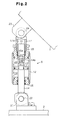
- Fig. 2 is a cross sectional view showing the hydraulic cylinder 6.
- the cylinder 6 includes a cylindrical tube 12, a piston 13, a piston rod 14, and a guide rod 15.
- the upper end of the piston 13 defines a head portion, and the lower end of the piston 13 defines a rod portion.
- the “upper” and “lower” directions referred to are taken from the upper and lower directions of Fig. 2.
- the tube 12 includes a body 12a.
- the upper end of the body 12a is closed by a head piece 16 and a guide piece 17.
- the lower end of the body 12a is closed by a rod piece 18.
- the piston 13 defines a rod chamber 19 and a head chamber 20 in the tube 12.
- the piston rod 14 extends through the rod chamber 19 and is fixed to the piston 13.
- the guide rod 15 extends through the head chamber 20 and is fixed to the piston 13.
- the piston rod 14 has a threaded male end 14a, which extends through the piston 13 and into the head chamber 20.
- the guide rod 15 has a threaded female end 15a, which engages the male end 14a.
- the other end of the piston rod 14 (the lower end) extends through the rod piece 18 and out of the tube 12.
- the other end of the guide rod 15 (the upper end) is slidably supported by a bearing 16a in the head piece 16 and is accommodated in a cavity 17a, which is defined in the guide piece 17.
- the threaded engagement between the male end 14a of the piston rod 14 and the female end 15a of the guide rod 15 forms a single integral rod.
- the piston 13 is located at the middle of the single rod.
- the cross sectional area of the guide rod 15 is equal to that of the piston rod 14. Therefore, the cross sectional area (or the piston are) that receives pressure is the same in the head side and in the rod side of the piston 13.
- the lower end of the piston rod 14 is pivotally supported about a pin 22 on a bracket 21, which is fixed to the rear axle beam 2.
- the upper end of the guide piece 17 is pivotally supported about a pin 24 on a bracket 23, which is fixed to the body frame 1.
- the electromagnetic control valve 7 has associated ports a, c, and associated ports b, d.
- the electromagnetic control valve 7 incorporates an electromagnetic solenoid 25, which shifts the control valve 7 between positions 7a and 7b. At position 7a, the electromagnetic control valve 7 disconnects port a from port c, and it disconnects port b from port d. At position 7b, the control valve 7 connects port a with port c, and port b with port d.
- a spring 26 is arranged in the control valve 7. When the electromagnetic solenoid 25 is de-excited, the control valve 7 is held at position 7a by the force of the spring 26. When the solenoid 25 is excited, the valve 7 is shifted to position 7b against the force of the spring 26. Therefore, the electromagnetic control valve 7 is normally closed.
- Port a is connected with the rod chamber 19 by way of the passage 9a.
- Port b is connected with the head chamber 20 by way of the passage 9b.
- Port c is connected with the accumulator 8 by way of the passage 10a.
- Port d is connected with the accumulator 8 by way of the passage 10b.
- the hydraulic cylinder 6 restricts the pivotal movement of the rear axle beam 2 relative to the body frame 1 by stopping the flow of the hydraulic oil between the chambers 19, 20.
- the control valve 7 is shifted to position 7b
- the rod chamber 19 and the head chamber 20 are connected to each other by way of the passages 9a, 9b and the accumulator 8.
- the hydraulic cylinder 6 permits the pivotal movement of the rear axle beam 2 relative to the body frame 1 by permitting the hydraulic oil to flow between the chambers 19, 20.
- the hydraulic cylinder 6 restrains the pivotal movement of the rear axle beam 2 by the resistance generated as hydraulic oil passes through passages 9a and 9b.
- the axle pivoting controller 11 excites the electromagnetic control valve 7.
- the axle pivoting controller 11 de-excites the electromagnetic control valve 7 and restricts the pivotal movement of the rear axle beam 2.
- the predetermined conditions are unsatisfied when the height to which the cargo is lifted, the angle of the steered wheels 5, and the traveling speed of the vehicle exceed certain values.
- the height of the cargo is detected by a height sensor H.
- the angle of the wheels 5 is detected by a steering angle sensor S.
- the traveling speed of the vehicle is detected by a velocity sensor V.
- the piston rod 14 projects from the cylinder 6.
- the piston 13 thus moves toward the rear axle beam 2 and receives pressure from the hydraulic oil in the rod chamber 19. This restrains the axial movement of the piston rod 14 and the pivotal movement of the rear axle beam 2 relative to the body frame 1.
- the rear axle beam 2 pivots counterclockwise at an appropriate velocity. Since the cross sectional area of the piston 13 is equal in the head chamber 20 and the rod chamber 19, the piston 13 receives the same pressure in the head chamber 20 and the rod chamber 19 when the piston 13 moves axially. Therefore, the retraction velocity of the piston 13 is equal to the projection velocity of the piston 13.
- the pivoting velocity of the rear axle beam 2 relative to the body frame 1 is the same when the rear axle beam 2 tilts clockwise and counterclockwise, as viewed in Fig. 2.
- volume of the hydraulic oil discharged from one of the oil chambers 19, 20 is the same as the volume of the hydraulic oil that enters the other oil chamber 19, 20.
- the electromagnetic control valve 7 may be normally open. In this case, if the controller 11 malfunctions and the electromagnetic control valve 7 cannot be controlled, the rod chamber 19 and the head chamber 20 are connected. This permits pivoting of the rear axle beam 2. Therefore, the rear axle beam 2 is permitted to pivot, even if the controller 11 malfunctions. Accordingly, traction is maintained by all four wheels of the forklift and the ground as the forklift travels along unpaved roads. Thus, the forklift can be driven even if the road is unpaved before being serviced.
- the piston rod 14 may be connected to the body frame 1 and the guide rod 15 may be connected to the rear axle beam 2.
- the cylinder 6 may be inverted from the orientation shown in Fig. 2.
- the piston rod 14 and the guide rod 15 may be fixed to the piston 13 by welding, fasteners such as bolts, press fitting, and other appropriate means.
- the cross sections of the piston rod 14 and the guide rod 15 do not have to be circular and may be polygonal.
- the head piece 16 and the guide piece 17 may be fixed to each other in an integral manner.
Landscapes
- Engineering & Computer Science (AREA)
- Mechanical Engineering (AREA)
- General Engineering & Computer Science (AREA)
- Structural Engineering (AREA)
- Transportation (AREA)
- Life Sciences & Earth Sciences (AREA)
- Civil Engineering (AREA)
- Geology (AREA)
- Physics & Mathematics (AREA)
- Fluid Mechanics (AREA)
- Vehicle Body Suspensions (AREA)
- Forklifts And Lifting Vehicles (AREA)
- Fluid-Damping Devices (AREA)
Claims (4)
- Hydraulische Vorrichtung, die bei einem Industriefahrzeug verwendet wird, die einen Hydraulikzylinder (6) hat, der zwischen einen Fahrzeugrahmen (1) und eine Achse (2) zwischengesetzt ist, die schwingfähig mit dem Rahmen (1) gekoppelt ist, wobei ein hydraulischer Durchgang (9a, 9b) eine erste Kammer (19) mit einer zweiten Kammer (20) verbindet, die durch einen Kolben (13) in einer Zylindereinfassung (12) definiert sind, wobei der Kolben (13) gemäß einem Differentialdruck in der ersten Kammer (19) und der zweiten Kammer (20) bewegbar ist und eine erste Fläche, die die erste Kammer (19) definiert, und eine zweite Fläche hat, die die zweite Kammer (20) definiert, wobei die erste Fläche einen Flächeninhalt hat, der derjenigen der zweiten Fläche gleich ist, wobei ein Zylinderstab (14) bezüglich der Zylindereinfassung (12) wahlweise ausfährt und einfährt, um eine Schwingbewegung der Achse (2) zu absorbieren, wobei der Hydraulikdurchgang (9a, 9b) wahlweise geöffnet und geschlossen wird, wobei der Kolbenstab (14) von der ersten Fläche des Kolbens (13) vorsteht, sich durch die erste Kammer (19) erstreckt und mit einem von dem Rahmen (1) und der Achse (2) verbunden ist, und wobei ein Führungsstab (15) von der zweiten Fläche des Kolben 13 vorsteht und sich durch die zweite Kammer (20) erstreckt, wobei der Kolbenstab (14) eine Querschnittsfläche hat, die derjenigen des Führungsstabs (15) gleich ist,
gekennzeichnet durch
ein zylindrisches Führungsstück (17), das gleitfähig den Führungsstab (15) aufnimmt, wobei das Führungsstück (17) zwischen den Führungsstab (15) und das andere von dem Rahmen und der Achse (2) zwischengesetzt ist, wobei der Hydraulikdurchgang (9a, 9b) auf der Grundlage von zumindest entweder einem Fahrzustand oder einem Lastzustand des Industriefahrzeugs wahlweise geöffnet und geschlossen wird, wobei ein Steuerventil (7) in dem Hydraulikdurchgang (9a, 9b) angeordnet ist, um wahlweise geöffnet und geschlossen zu werden, um eine Hydraulikströmung in dem Durchgang (9a, 9b) zu gestatten oder zu unterbinden, und wobei ein Speicher (8) in dem Hydraulikdurchgang (9a, 9b) angeordnet ist. - Vorrichtung gemäß Anspruch 1,
gekennzeichnet durch
eine Steuerung (11) zum Steuern des elektromagnetischen Steuerventils (7) gemäß zumindest entweder dem Fahrzustand oder dem Lastzustand des Industriefahrzeugs. - Vorrichtung gemäß Anspruch 1,
dadurch gekennzeichnet, dass
das elektromagnetische Steuerventil (7) den Hydraulikdurchgang (9a, 9b) schließt, wenn das Ventil (7) deaktiviert ist. - Vorrichtung gemäß Anspruch 1,
dadurch gekennzeichnet, dass
das Industriefahrzeug einen Gabelstapler umfasst.
Applications Claiming Priority (3)
| Application Number | Priority Date | Filing Date | Title |
|---|---|---|---|
| JP9197205A JPH1137204A (ja) | 1997-07-23 | 1997-07-23 | 産業車両用揺動規制装置及び油圧シリンダ |
| JP197205/97 | 1997-07-23 | ||
| JP19720597 | 1997-07-23 |
Publications (2)
| Publication Number | Publication Date |
|---|---|
| EP0893290A1 EP0893290A1 (de) | 1999-01-27 |
| EP0893290B1 true EP0893290B1 (de) | 2002-12-04 |
Family
ID=16370576
Family Applications (1)
| Application Number | Title | Priority Date | Filing Date |
|---|---|---|---|
| EP98113695A Expired - Lifetime EP0893290B1 (de) | 1997-07-23 | 1998-07-22 | Steuerungseinrichtung und hydraulischer Zylinder für eine schwenkbare Nutzfahrzeugachse |
Country Status (8)
| Country | Link |
|---|---|
| US (1) | US6206154B1 (de) |
| EP (1) | EP0893290B1 (de) |
| JP (1) | JPH1137204A (de) |
| KR (1) | KR100366470B1 (de) |
| AU (1) | AU708494B2 (de) |
| CA (1) | CA2243732C (de) |
| DE (1) | DE69809847T2 (de) |
| TW (1) | TW416916B (de) |
Cited By (1)
| Publication number | Priority date | Publication date | Assignee | Title |
|---|---|---|---|---|
| US7963528B2 (en) | 2007-07-21 | 2011-06-21 | J.C. Bamford Excavators Limited | Working machine |
Families Citing this family (5)
| Publication number | Priority date | Publication date | Assignee | Title |
|---|---|---|---|---|
| US6755113B2 (en) * | 2002-07-30 | 2004-06-29 | Ha Wse Company Limited | Accumulated semi-active hydraulic damper |
| US8328296B2 (en) * | 2004-06-10 | 2012-12-11 | Hitachi Construction Machinery Co., Ltd. | Work vehicle control device |
| JP2008008384A (ja) * | 2006-06-28 | 2008-01-17 | Nippon Yusoki Co Ltd | 油圧装置、及びこれを備えた産業車両の車輪懸架装置 |
| DE102010042673A1 (de) * | 2010-10-20 | 2012-04-26 | Deere & Company | Stabilisierungsvorrichtung für ein Kraftfahrzeug |
| CN118257750B (zh) * | 2024-05-31 | 2024-09-17 | 杭州安衡迅科技有限公司 | 液压作动系统及汽车减振结构 |
Family Cites Families (27)
| Publication number | Priority date | Publication date | Assignee | Title |
|---|---|---|---|---|
| GB736383A (en) * | 1952-08-29 | 1955-09-07 | Renault | Improvements in and relating to elastic suspensions for vehicles |
| AT283197B (de) | 1968-04-18 | 1970-07-27 | Wagner Appbau Ernst | Hubstapler, Transportfahrzeug od.dgl. |
| US3726368A (en) * | 1970-10-30 | 1973-04-10 | P Taylor | Fluid amplified liquid spring shocks and/or shock absorbers |
| JPS54108641A (en) | 1978-02-14 | 1979-08-25 | Toshiba Corp | Recording element |
| JPS58183307A (ja) | 1982-04-17 | 1983-10-26 | Toyoda Autom Loom Works Ltd | 産業車両における車軸固定装置 |
| JPS58214406A (ja) * | 1982-06-05 | 1983-12-13 | Toyoda Autom Loom Works Ltd | 産業車両における車軸固定装置 |
| SE451189B (sv) * | 1983-08-05 | 1987-09-14 | Umea Mekaniska Ab | Anordning vid terrenggaende fordon eller maskiner |
| DE3414257C2 (de) * | 1984-04-14 | 1993-12-02 | Bosch Gmbh Robert | Federelement mit veränderbarer Härte für Fahrzeuge |
| CH665940A5 (de) * | 1984-11-09 | 1988-06-30 | Giroflex Entwicklungs Ag | Verstellvorrichtung, insbesondere fuer neigbare und hoehenverstellbare stuehle. |
| US4703683A (en) * | 1985-02-04 | 1987-11-03 | Grumman Aerospace Corporation | Fluid actuator with internal locking |
| DE3524862A1 (de) | 1985-04-12 | 1986-10-30 | Robert Bosch Gmbh, 7000 Stuttgart | Vorrichtung zur daempfung von bewegungsablaeufen |
| US4810849A (en) * | 1987-01-21 | 1989-03-07 | Enertrols, Inc. | Weld gun control |
| JPH01135298A (ja) * | 1987-11-20 | 1989-05-26 | Matsushita Electric Ind Co Ltd | 超電導平板スピーカ |
| DE3803888A1 (de) * | 1988-02-09 | 1989-08-17 | Boge Ag | Regelbarer schwingungsdaempfer |
| US5188248A (en) * | 1990-04-27 | 1993-02-23 | Gehl Company | Stabilizing cylinder for a rough terrain forklift |
| FR2681563A1 (fr) | 1991-09-20 | 1993-03-26 | Faucheux Ind Sa | Dispositif stabilisateur pour vehicule agricole. |
| DE4235264B4 (de) * | 1992-10-20 | 2004-07-08 | Same Deutz-Fahr S.P.A., Treviglio | Hydraulische Vorderachssicherung und Blockierung für ein landwirtschaftliches Fahrzeug |
| US5639119A (en) * | 1992-12-04 | 1997-06-17 | Trak International, Inc. | Forklift stabilizing apparatus |
| JP3087487B2 (ja) * | 1992-12-26 | 2000-09-11 | 株式会社豊田自動織機製作所 | リーチ式フォークリフトのサスペンション装置 |
| PL170036B1 (pl) * | 1993-04-28 | 1996-10-31 | Urzadzen Mechanicznych Kamax S | Amortyzator elastomerowy PL |
| US5549281A (en) * | 1994-01-25 | 1996-08-27 | Hall; G. Gordon | Liquid spring for punch press |
| US5452883A (en) * | 1994-06-02 | 1995-09-26 | Ni-Tech, Inc. | Gas spring |
| US5813697A (en) * | 1994-12-05 | 1998-09-29 | Trak International, Inc. | Forklift stabilizing apparatus |
| GB2303193B (en) * | 1995-07-13 | 1998-10-14 | Draftex Ind Ltd | Gas spring |
| GB2304170A (en) * | 1995-08-08 | 1997-03-12 | Btr Antivibration Syst Inc | Fluid damping mount |
| CN1078857C (zh) * | 1996-03-19 | 2002-02-06 | 株式会社丰田自动织机制作所 | 工业车辆的控制装置 |
| US5725239A (en) * | 1996-03-26 | 1998-03-10 | Monroe Auto Equipment | Adaptive load dependent suspension system |
-
1997
- 1997-07-23 JP JP9197205A patent/JPH1137204A/ja active Pending
-
1998
- 1998-07-21 TW TW087111858A patent/TW416916B/zh not_active IP Right Cessation
- 1998-07-22 EP EP98113695A patent/EP0893290B1/de not_active Expired - Lifetime
- 1998-07-22 KR KR10-1998-0029378A patent/KR100366470B1/ko not_active Expired - Lifetime
- 1998-07-22 AU AU77445/98A patent/AU708494B2/en not_active Expired
- 1998-07-22 DE DE69809847T patent/DE69809847T2/de not_active Expired - Lifetime
- 1998-07-22 US US09/120,417 patent/US6206154B1/en not_active Expired - Lifetime
- 1998-07-22 CA CA002243732A patent/CA2243732C/en not_active Expired - Lifetime
Cited By (1)
| Publication number | Priority date | Publication date | Assignee | Title |
|---|---|---|---|---|
| US7963528B2 (en) | 2007-07-21 | 2011-06-21 | J.C. Bamford Excavators Limited | Working machine |
Also Published As
| Publication number | Publication date |
|---|---|
| TW416916B (en) | 2001-01-01 |
| KR100366470B1 (ko) | 2003-10-11 |
| AU7744598A (en) | 1999-02-04 |
| KR19990014043A (ko) | 1999-02-25 |
| DE69809847D1 (de) | 2003-01-16 |
| CA2243732C (en) | 2002-01-22 |
| AU708494B2 (en) | 1999-08-05 |
| CA2243732A1 (en) | 1999-01-23 |
| DE69809847T2 (de) | 2003-05-28 |
| US6206154B1 (en) | 2001-03-27 |
| EP0893290A1 (de) | 1999-01-27 |
| JPH1137204A (ja) | 1999-02-12 |
Similar Documents
| Publication | Publication Date | Title |
|---|---|---|
| JP3120859B2 (ja) | 切り替え可能なロール・スタビライザバー | |
| EP0867315B1 (de) | Achsregelungsvorrichtung für Industriefahrzeuge | |
| US5383680A (en) | Anti-roll system for wheeled vehicles | |
| AU708429B2 (en) | Axle tilt control apparatus for industrial vehicles | |
| EP0818332B1 (de) | Rollregelungssystem | |
| US6556907B1 (en) | Vehicle suspension system | |
| EP1116610B1 (de) | Aufhängungsvorrichtung für ein vierrädriges Fahrzeug | |
| EP0747281A2 (de) | Blockiermechanismus für eine selbstlenkende Achse | |
| US5505480A (en) | Controlled stabilizer bar attachment apparatus for improved suspension articulation | |
| US20040061292A1 (en) | Articulation compensated hydraulic suspension system | |
| EP0893290B1 (de) | Steuerungseinrichtung und hydraulischer Zylinder für eine schwenkbare Nutzfahrzeugachse | |
| US6203027B1 (en) | Structure for supporting fluid pressure cylinders used to control pivoting of vehicle axles | |
| WO2000069664A1 (en) | Active suspension system and components therefor | |
| KR20020055815A (ko) | 차량의 안티 롤 제어장치 | |
| JPH0722323Y2 (ja) | 連結車両の流体圧サスペンション装置 | |
| KR100534997B1 (ko) | 리이프스프링의 탄성력 조정장치 | |
| JP2861726B2 (ja) | 車両のサスペンション装置 | |
| AU4525200A (en) | Active suspension system and components therefor | |
| KR19980049929A (ko) | 충격감지 제어형 트랙터 현가장치 | |
| KR19980016976U (ko) | 차량의 수평유지용 현가장치 | |
| MXPA96001820A (en) | Suspension lock mechanism with auto-direcc | |
| JPS62273111A (ja) | 自動車用アンチロ−ルシステム |
Legal Events
| Date | Code | Title | Description |
|---|---|---|---|
| PUAI | Public reference made under article 153(3) epc to a published international application that has entered the european phase |
Free format text: ORIGINAL CODE: 0009012 |
|
| 17P | Request for examination filed |
Effective date: 19980722 |
|
| AK | Designated contracting states |
Kind code of ref document: A1 Designated state(s): DE FR GB |
|
| AX | Request for extension of the european patent |
Free format text: AL;LT;LV;MK;RO;SI |
|
| AKX | Designation fees paid |
Free format text: DE FR GB |
|
| 17Q | First examination report despatched |
Effective date: 20010403 |
|
| RAP1 | Party data changed (applicant data changed or rights of an application transferred) |
Owner name: KAYABA KOGYO KABUSHIKI KAISHA Owner name: KABUSHIKI KAISHA TOYOTA JIDOSHOKKI |
|
| GRAG | Despatch of communication of intention to grant |
Free format text: ORIGINAL CODE: EPIDOS AGRA |
|
| GRAG | Despatch of communication of intention to grant |
Free format text: ORIGINAL CODE: EPIDOS AGRA |
|
| GRAH | Despatch of communication of intention to grant a patent |
Free format text: ORIGINAL CODE: EPIDOS IGRA |
|
| GRAH | Despatch of communication of intention to grant a patent |
Free format text: ORIGINAL CODE: EPIDOS IGRA |
|
| GRAA | (expected) grant |
Free format text: ORIGINAL CODE: 0009210 |
|
| AK | Designated contracting states |
Kind code of ref document: B1 Designated state(s): DE FR GB |
|
| REG | Reference to a national code |
Ref country code: GB Ref legal event code: FG4D |
|
| REF | Corresponds to: |
Ref document number: 69809847 Country of ref document: DE Date of ref document: 20030116 |
|
| ET | Fr: translation filed | ||
| PLBE | No opposition filed within time limit |
Free format text: ORIGINAL CODE: 0009261 |
|
| STAA | Information on the status of an ep patent application or granted ep patent |
Free format text: STATUS: NO OPPOSITION FILED WITHIN TIME LIMIT |
|
| 26N | No opposition filed |
Effective date: 20030905 |
|
| REG | Reference to a national code |
Ref country code: DE Ref legal event code: R082 Ref document number: 69809847 Country of ref document: DE Representative=s name: TBK, DE Ref country code: DE Ref legal event code: R081 Ref document number: 69809847 Country of ref document: DE Owner name: KYB CORPORATION, JP Free format text: FORMER OWNERS: KABUSHIKI KAISHA TOYOTA JIDOSHOKKI, KARIYA-SHI, AICHI-KEN, JP; KAYABA KOGYO K.K., TOKIO/TOKYO, JP Ref country code: DE Ref legal event code: R081 Ref document number: 69809847 Country of ref document: DE Owner name: KABUSHIKI KAISHA TOYOTA JIDOSHOKKI, KARIYA-SHI, JP Free format text: FORMER OWNERS: KABUSHIKI KAISHA TOYOTA JIDOSHOKKI, KARIYA-SHI, AICHI-KEN, JP; KAYABA KOGYO K.K., TOKIO/TOKYO, JP |
|
| REG | Reference to a national code |
Ref country code: FR Ref legal event code: PLFP Year of fee payment: 19 |
|
| REG | Reference to a national code |
Ref country code: FR Ref legal event code: PLFP Year of fee payment: 20 |
|
| PGFP | Annual fee paid to national office [announced via postgrant information from national office to epo] |
Ref country code: FR Payment date: 20170613 Year of fee payment: 20 |
|
| PGFP | Annual fee paid to national office [announced via postgrant information from national office to epo] |
Ref country code: GB Payment date: 20170719 Year of fee payment: 20 Ref country code: DE Payment date: 20170719 Year of fee payment: 20 |
|
| REG | Reference to a national code |
Ref country code: DE Ref legal event code: R071 Ref document number: 69809847 Country of ref document: DE |
|
| REG | Reference to a national code |
Ref country code: GB Ref legal event code: PE20 Expiry date: 20180721 |
|
| PG25 | Lapsed in a contracting state [announced via postgrant information from national office to epo] |
Ref country code: GB Free format text: LAPSE BECAUSE OF EXPIRATION OF PROTECTION Effective date: 20180721 |