EP0892929B1 - Anordnung zur vermessung der koordinaten mehrerer, an einem objekt angebrachten, retroreflektoren - Google Patents
Anordnung zur vermessung der koordinaten mehrerer, an einem objekt angebrachten, retroreflektoren Download PDFInfo
- Publication number
- EP0892929B1 EP0892929B1 EP97916460A EP97916460A EP0892929B1 EP 0892929 B1 EP0892929 B1 EP 0892929B1 EP 97916460 A EP97916460 A EP 97916460A EP 97916460 A EP97916460 A EP 97916460A EP 0892929 B1 EP0892929 B1 EP 0892929B1
- Authority
- EP
- European Patent Office
- Prior art keywords
- light
- arrangement according
- sensor
- retroreflector
- retro
- Prior art date
- Legal status (The legal status is an assumption and is not a legal conclusion. Google has not performed a legal analysis and makes no representation as to the accuracy of the status listed.)
- Expired - Lifetime
Links
Images
Classifications
-
- G—PHYSICS
- G01—MEASURING; TESTING
- G01S—RADIO DIRECTION-FINDING; RADIO NAVIGATION; DETERMINING DISTANCE OR VELOCITY BY USE OF RADIO WAVES; LOCATING OR PRESENCE-DETECTING BY USE OF THE REFLECTION OR RERADIATION OF RADIO WAVES; ANALOGOUS ARRANGEMENTS USING OTHER WAVES
- G01S17/00—Systems using the reflection or reradiation of electromagnetic waves other than radio waves, e.g. lidar systems
- G01S17/02—Systems using the reflection of electromagnetic waves other than radio waves
- G01S17/06—Systems determining position data of a target
- G01S17/42—Simultaneous measurement of distance and other co-ordinates
-
- G—PHYSICS
- G01—MEASURING; TESTING
- G01S—RADIO DIRECTION-FINDING; RADIO NAVIGATION; DETERMINING DISTANCE OR VELOCITY BY USE OF RADIO WAVES; LOCATING OR PRESENCE-DETECTING BY USE OF THE REFLECTION OR RERADIATION OF RADIO WAVES; ANALOGOUS ARRANGEMENTS USING OTHER WAVES
- G01S17/00—Systems using the reflection or reradiation of electromagnetic waves other than radio waves, e.g. lidar systems
- G01S17/74—Systems using reradiation of electromagnetic waves other than radio waves, e.g. IFF, i.e. identification of friend or foe
-
- G—PHYSICS
- G01—MEASURING; TESTING
- G01S—RADIO DIRECTION-FINDING; RADIO NAVIGATION; DETERMINING DISTANCE OR VELOCITY BY USE OF RADIO WAVES; LOCATING OR PRESENCE-DETECTING BY USE OF THE REFLECTION OR RERADIATION OF RADIO WAVES; ANALOGOUS ARRANGEMENTS USING OTHER WAVES
- G01S17/00—Systems using the reflection or reradiation of electromagnetic waves other than radio waves, e.g. lidar systems
- G01S17/87—Combinations of systems using electromagnetic waves other than radio waves
- G01S17/875—Combinations of systems using electromagnetic waves other than radio waves for determining attitude
-
- G—PHYSICS
- G01—MEASURING; TESTING
- G01S—RADIO DIRECTION-FINDING; RADIO NAVIGATION; DETERMINING DISTANCE OR VELOCITY BY USE OF RADIO WAVES; LOCATING OR PRESENCE-DETECTING BY USE OF THE REFLECTION OR RERADIATION OF RADIO WAVES; ANALOGOUS ARRANGEMENTS USING OTHER WAVES
- G01S7/00—Details of systems according to groups G01S13/00, G01S15/00, G01S17/00
- G01S7/48—Details of systems according to groups G01S13/00, G01S15/00, G01S17/00 of systems according to group G01S17/00
- G01S7/497—Means for monitoring or calibrating
- G01S2007/4975—Means for monitoring or calibrating of sensor obstruction by, e.g. dirt- or ice-coating, e.g. by reflection measurement on front-screen
- G01S2007/4977—Means for monitoring or calibrating of sensor obstruction by, e.g. dirt- or ice-coating, e.g. by reflection measurement on front-screen including means to prevent or remove the obstruction
-
- G—PHYSICS
- G01—MEASURING; TESTING
- G01S—RADIO DIRECTION-FINDING; RADIO NAVIGATION; DETERMINING DISTANCE OR VELOCITY BY USE OF RADIO WAVES; LOCATING OR PRESENCE-DETECTING BY USE OF THE REFLECTION OR RERADIATION OF RADIO WAVES; ANALOGOUS ARRANGEMENTS USING OTHER WAVES
- G01S7/00—Details of systems according to groups G01S13/00, G01S15/00, G01S17/00
- G01S7/48—Details of systems according to groups G01S13/00, G01S15/00, G01S17/00 of systems according to group G01S17/00
- G01S7/497—Means for monitoring or calibrating
Definitions
- the invention relates to an arrangement for measuring the coordinates of a or several retroreflector (s) attached to an object according to the generic term of claim 1.
- A must at every object point of interest self-illuminating element can be attached.
- the element must be the surrounding one Illuminate the room so that enough light hits the sensor so that the image of the Elements in the sensor level can be clearly distinguished from the environment can. To do this, the element must be supplied with energy. It means that either an energy source must be attached - and the size of the Elements becomes relatively large - or supply cables are laid to the object have to. The effort involved in attaching to a measurement object is therefore relative large.
- the Contrast between the image of the environment and the image of the brand by a correspondingly intensive or selective illumination of the measurement volume becomes. If there are reflective or shiny surfaces in the measuring field, With this type of measurement, considerable measurement errors can occur under certain circumstances. Furthermore, the strong illumination of the measuring volume is often only relative by one great energy expenditure achievable.
- the methods based on the bearing of a retroreflector are very efficient are based, since this contains almost all of the light hitting it reflected parallel offset.
- the methods are based not on an image of the object or brand surface, but on one Bearing the retroreflector center with a laser beam. From the measuring position it is aligned with the retroreflector. Characteristic of these processes is that the position of the reflector is determined from the angular position of the laser.
- the Optical sensors used in these processes are used exclusively for Minimization or compensation of DF errors used: becomes the center of the Retroreflector hit by the laser beam, the beam is reflected back in itself, otherwise the beam is reflected back offset in parallel.
- the beam cross section of the Laser beam at the measuring position smaller (usually ⁇ 10%) of the cross-sectional area of the retroreflector.
- Another characteristic of these measuring methods is the Determination of the reflector coordinates by measuring the bearing angle must be set and determined accordingly.
- the measuring systems usually contain a high-precision - and accordingly expensive or maintenance-intensive - mechanics.
- Alignment of the laser beam on the retroreflector represents at least at the beginning a series of measurements - usually manually - must be carried out. In a big one Measurement field, this "trapping" of the beam may be very critical and with a considerable amount of time.
- WO 91/09325 describes a device for detecting the position of an object that are used for the purpose of performing a coupling maneuver of two Spacecraft has been designed.
- the device has at least three Retroreflectors, which are illuminated by a light beam, provided that Light source is sufficiently far from the location of the reflectors.
- the light source is on the first spacecraft, the retroreflectors on the second Spacecraft, both spacecraft approach each other for coupling.
- the second spacecraft provides a spherically curved mirror called Retroreflector is used, both spacecraft have a certain minimum distance below. That of the retroreflective surfaces on the second spacecraft reflected light rays pass a beam splitter, which a light detector in Form is subordinate to a CCD camera.
- the exact position detection of the second Spacecraft relative to the first spacecraft is done by evaluating Reflection events on at least three reflectors, each on three spatially different places are appropriate. Is the mutual distance the two approaching spaceships less than the one above Minimum distance, so it is necessary to activate two additional light sources again three reflection events - but now on the surface of the spherical Mirror - to be able to evaluate accordingly.
- the object of the invention is an arrangement for measuring the coordinates to specify at least one retroreflector attached to an object, that the technical effort for accurate measurement value acquisition should be reduced, with a constant or even improved measurement data quality.
- the detector unit is outside a point P ' is located in the point corresponding to the pupil of the lighting unit Beam path of the light reflected by the retroreflector corresponds to where the Position and / or shape of the detected light spot with the position of the Retroreflector changes, and that the lighting unit consists of two or more Light sources with different pupil positions exist that alternate in time are actuated and / or in the spectral composition or in Polarization state emit different light.
- the invention is based on the fact that it starts from a lighting unit Light that falls on a retroreflective brand, is reflected back into itself and with the help of a beam splitter attached in front of the lighting unit a detector is steered, the detector being outside the point P ', which the pupil corresponds to the lighting, is arranged, making a determination the brand position in the coordinate system of the lighting / detector unit becomes possible.
- the lighting / detector unit for this determination cannot be aimed precisely at the center of the reflector.
- the measurement of the reflector coordinates can be done directly, i.e. without determination of DF angles, from measuring the coordinates of the in the sensor plane resulting light spot occur. In contrast to the procedures with active or scattering brands, this is already without the use of imaging optical Elements possible.
- a contactless one can easily be made One or more object points are measured.
- a retroreflective mark for example a retroreflective one Foil.
- the mark can be small and therefore light. The Measuring the path movement of a small, fast object is under This is only possible under certain circumstances.
- the measuring head does not have to be precisely aligned with the reflector.
- the associated problems are not with an arrangement according to the invention more available.
- the beam path is very efficient, i.e. even for a sensor with a measuring range from several decimeters to meters (perpendicular to the optical axis), the lighting can already be made using a light-emitting diode (LED) respectively.
- LED light-emitting diode
- PSD position sensitive photo diode
- a modulated LED can measure frequencies in the MHz range and extreme interference suppression can be achieved.
- Imaging sensors used or the image visual or evaluated photographically can measure several object points or be recorded.
- a telecentric lighting (Direction or) plane perpendicular to the optical axis can be determined.
- the beam angle or two mutually perpendicular beam angles to the optical axis are determined.
- the effective area in the illuminated measuring field changes and thus the reflected intensity.
- telecentric lighting can over an intensity measurement of this tilt of the reflector can be determined. at divergent or convergent lighting, the intensity depends on the tilt and the distance of the reflector from the measuring head.
- a spherical reflector or a spherical section shaped reflector is used, the influence of a tilt on the measured Intensity eliminated because the effective area of the retroreflector Tilt does not change.
- the determination of the distance via a measurement of the the intensity of the sensor can then not be falsified by tilting become.
- the center of gravity coordinates of the light spot in the sensor plane provide a measure for the angle at which the reflector center is seen from the projection point, located. If it is illuminated from different projection points, so are different center of gravity coordinates measured in the sensor plane. From the difference in the center of gravity coordinates, the distance of the Reflector can be determined. This distance determination can alternatively or in addition to the distance measurement by means of the intensity.
- Another alternative measuring method for determining the distance is one simultaneous measurement of the beam angle with several, at different Reference points attached lighting / detector units. Because of everyone Illumination unit reflected back light reflected on the retroreflector there is no mutual interference (as is the case with the Measurement with the method according to A. would occur). The reflector coordinates are with a triangulation calculation from the measured beam angles derivable.
- the advantage of a corresponding design is the possible increase the measuring frequency.
- An alternative to this method is to measure with a imaging sensor (CCD matrix).
- the measuring frequency that can be achieved is in the Order of magnitude 10 Hz.
- the measurement of several points already with position-resolving sensors e.g. PSD
- two retroreflective marks at the origin and tip of a robotic hand be attached.
- the tilting of the Brand area can already be determined with position-resolving detectors.
- the tilt can be determined from the difference between these focal points determined and possibly the error of the distance measurement resulting from the tilting be compensated.
- the determined middle position of the mark with the lighting blue light versus that used when lighting with red light is determined to be postponed.
- a perpendicular to the optical axis of the Sensor-oriented brand is the distance between the light spot focal points in the Sensor level only depends on the distance to the measuring head or (with a telecentric lighting) constant.
- tilting the brand around the The axis is perpendicular to the optical axis and perpendicular to the color gradient a reduction in this measured distance. Is the course of the distance (for a tilt) in the measuring range or it becomes known for the brand measured, the tilting of the Brand can be determined.
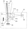
- the single figure shows an embodiment of the invention in which the Illumination beam path is split into partial beam paths that are temporal can be modulated differently.
- the light source for example, a multi-color light-emitting diode designated (6).
- a diffuser (7) which, for example, consists of a Hologram exists.
- the radiation emanating from it is homogeneous Illuminated light cone 1 (solid lines). It comes through the Beam splitter (11) on which the light of a similar illumination (6 ', 7') is coupled in, which is seen from the outside in a different position on or perpendicular to the optical axis and a different opening angle has (dashed line).
- each Brand acts like a combination of an (ideal) retroreflector with one each different color filters.
- mark 4 works in the red spectral range as a retroreflector and absorbs in the green spectral range.
- the mark 4 ' works exactly vice versa.
- the radiation striking these marks is in the measuring head reflected back. Part of this radiation reaches the beam splitter (3) Detector (5) (for example a PSD).
- the measurement frequency can be doubled by means of an additional wavelength-selective beam splitter (12) and a second one PSD (13), because then both LEDs at the same time (with each different colors) can be operated.
Description
Bei ihnen wird - sofern das Objekt selbst nicht die besondere optische Eigenschaft aufweist - am oder im zu vermessenden Objektpunkt eine besondere Markierung angebracht.
Gebräuchliche Markierungen sind:
- Probleme durch einen begrenzten Schärfentiefebereich bzw. Notwendigkeit der Fokussierung
- Verfälschung der Messung durch Abbildungsfehler, mangelnden Kontrast bzw. spiegelnde Oberflächen im Meßfeld.
- bei telezentrischer Beleuchtung ein Wert für die Verkippung der retroreflektierenden Marke, da es durch eine Verkippung der Marke zu einer Reduktion der wirksamen Retroreflektorfläche im beleuchteten Meßfeld kommt,
- bei divergenter oder konvergenter Beleuchtung kann der Abstand zwischen der Beleuchtungs- / Detektoreinheit und der Marke bestimmt werden.
Die Ausführung eines konvergenten Strahlengangs kann trotzdem in folgenden Fällen sinnvoll sein:
- Fremdlichtunterdrückung,
- Unterdrückung von Meßfehlern durch eine Verkippung der Marke,
- Unterdrückung des Einflusses einer Verschmutzung der Marke.
- die zeitlich aufeinanderfolgende Beleuchtung mit den unterschiedlichen Strahlungsarten,
- die Verwendung eines oder mehrerer farbempfindlicher Sensoren,
- die Aufteilung des Detektorstrahlengangs in mehrere Teilstrahlengänge zu Detektoren, die unterschiedlich auf die einzelnen Strahlungsarten ansprechen,
- eine wellenlängenselektive Strahlteilung oder
- die Aufteilung des Detektorstrahlengangs in mehrere unterschiedlich gefilterte Teilstrahlengänge zu den einzelnen Detektoren.
Claims (10)
- Anordnung zur Vermessung der Koordinaten mindestens eines, an einem Objekt angebrachten Retroreflektors, bei derdadurch gekennzeichnet,eine Beleuchtungseinheit vorgesehen ist, die Licht in Form eines Strahlenbündels über einen Strahlteiler derart auf die Objektoberfläche richtet, dass das Strahlenbündel eine größere Fläche als die Fläche des mindestens einen, auf der Objektoberfläche angebrachten Retroreflektors beleuchtet,vom Retroreflektor in sich zurückgeworfenes Licht am Strahlteiler vom Beleuchtungsstrahlengang getrennt wird, unddieses Licht auf eine Detektoreinheit auftrifft, mit der die Auftreffposition des detektierten Lichtflecks ermittelbar ist,daß sich die Detektoreinheit außerhalb eines Punktes P' befindet, der einem, der Pupille der Beleuchtungseinheit entsprechenden Punkt im Strahlengang des vom Retroreflektor zurückgeworfenen Lichts entspricht, wo sich die Position und/oder Form des detektierten Lichtflecks mit der Position des Retroreflektors ändert, unddaß die Beleuchtungseinheit aus zwei oder mehreren Lichtquellen mit unterschiedlicher Pupillenlage besteht, die zeitlich abwechselnd betätigbar sind und/oder in der spektralen Zusammensetzung oder im Polarisationszustand unterschiedliches Licht emittieren.
- Anordnung nach Anspruch 1,
gekennzeichnet durch Mittel zur Modulation des Lichts der Beleuchtungseinheit und zur Filterung des Signals der Detektoreinheit und/oder durch eine Blende (8) am Ort der Pupille P'. - Anordnung nach Anspruch 1 oder 2,
dadurch gekennzeichnet, dass der Retroreflektor als Kugel oder Kugelabschnitt ausgebildet ist und/oder aus einer retroreflektierenden Folie oder Schicht besteht. - Anordnung nach einem der Ansprüche 1 bis 3,
dadurch gekennzeichnet, dass der Detektor eine Mattscheibe, ein Film, eine Fotodiode, ein positionsauflösender Sensor oder bildauflösender Sensor in Art einer CCD-Zeile, Farbzeile, CCD-Matrixsensor oder CCD-Farbmatrixsensor ist. - Anordnung nach Anspruch 1,
dadurch gekennzeichnet, dass die Detektoreinheit einen für die unterschiedlichen Beleuchtungsarten geteilten Sensor, z.B. in Form eines Farbzeilen- oder Farbmatrix-Sensors, aufweist. - Anordnung nach Anspruch 1 oder 5,
dadurch gekennzeichnet, dass zwei oder mehrere Retroreflektoren mit wellenlängenselektiven oder polarisationsabhängigem Reflexionsverhalten vorgesehen sind. - Anordnung nach einem der Ansprüche 1 bis 7,
dadurch gekennzeichnet, dass die Retroreflektorfläche mehr als etwa 10% der ausgeleuchteten Fläche auf der Objektoberfläche beträgt und ein oder mehrere Filter auf der Retroreflektorfläche angebracht sind, die zu einer Änderung der zurückreflektierten Intensität in Abhängigkeit vom Spektralbereich oder vom Polarisationszustand der beleuchtenden Strahlung über eine oder zwei Richtungen der Reflektoroberfläche führen. - Anordnung nach einem der Ansprüche 1 bis 7,
dadurch gekennzeichnet, dass abbildende optische Elemente, insbesondere Linsen, Hohl- oder Parabolspiegel, in einzelnen Teilstrahlengängen angeordnet sind. - Anordnung zur Erfassung von Objekten, bei der mehrere der Anordnungen nach einem der Ansprüche 1 bis 8 auf der Objektoberfläche ausgerichtet sind.
- Verwendung der Anordnung nach einem der Ansprüche 1 bis 9 zur statischen oder dynamischen Vermessung der Genauigkeit von Robotern, zur Überwachung der Maßhaltigkeit oder der Flugbahn von Objekten, der Orts- oder Lageveränderung von Objekten oder der Orts- oder Lageveränderung von Körperteilen.
Applications Claiming Priority (3)
| Application Number | Priority Date | Filing Date | Title |
|---|---|---|---|
| DE19614108A DE19614108C1 (de) | 1996-04-10 | 1996-04-10 | Anordnung zur Vermessung der Koordinaten eines an einem Objekt angebrachten Retroreflektors |
| DE19614108 | 1996-04-10 | ||
| PCT/EP1997/001783 WO1997038327A1 (de) | 1996-04-10 | 1997-04-10 | Anordnung zur vermessung der koordinaten eines oder mehrerer, an einem objekt angebrachten, retroreflektor(en) |
Publications (2)
| Publication Number | Publication Date |
|---|---|
| EP0892929A1 EP0892929A1 (de) | 1999-01-27 |
| EP0892929B1 true EP0892929B1 (de) | 2002-11-13 |
Family
ID=7790857
Family Applications (1)
| Application Number | Title | Priority Date | Filing Date |
|---|---|---|---|
| EP97916460A Expired - Lifetime EP0892929B1 (de) | 1996-04-10 | 1997-04-10 | Anordnung zur vermessung der koordinaten mehrerer, an einem objekt angebrachten, retroreflektoren |
Country Status (5)
| Country | Link |
|---|---|
| US (1) | US6097491A (de) |
| EP (1) | EP0892929B1 (de) |
| AT (1) | ATE227852T1 (de) |
| DE (2) | DE19614108C1 (de) |
| WO (1) | WO1997038327A1 (de) |
Families Citing this family (25)
| Publication number | Priority date | Publication date | Assignee | Title |
|---|---|---|---|---|
| EP1220596A1 (de) * | 2000-12-29 | 2002-07-03 | Icos Vision Systems N.V. | Verfahren und Einrichtung zur Lageerfassung der Anschlusskontakte elektronischer Bauelemente |
| US7360703B2 (en) * | 2004-09-23 | 2008-04-22 | Ut-Battelle, Llc | Laser scanning system for object monitoring |
| CA2553474A1 (en) * | 2005-07-20 | 2007-01-20 | Boreal Laser Inc. | Laser sensing apparatus and method |
| US9482755B2 (en) | 2008-11-17 | 2016-11-01 | Faro Technologies, Inc. | Measurement system having air temperature compensation between a target and a laser tracker |
| DE102009028068B4 (de) * | 2009-07-29 | 2023-05-25 | Dr. Johannes Heidenhain Gmbh | Positionsmessvorrichtung |
| US8237934B1 (en) * | 2009-11-18 | 2012-08-07 | The Boeing Company | Center marking nest for method of precision locating |
| US9772394B2 (en) | 2010-04-21 | 2017-09-26 | Faro Technologies, Inc. | Method and apparatus for following an operator and locking onto a retroreflector with a laser tracker |
| US9400170B2 (en) | 2010-04-21 | 2016-07-26 | Faro Technologies, Inc. | Automatic measurement of dimensional data within an acceptance region by a laser tracker |
| US9377885B2 (en) | 2010-04-21 | 2016-06-28 | Faro Technologies, Inc. | Method and apparatus for locking onto a retroreflector with a laser tracker |
| US8619265B2 (en) | 2011-03-14 | 2013-12-31 | Faro Technologies, Inc. | Automatic measurement of dimensional data with a laser tracker |
| LU91737B1 (en) * | 2010-09-17 | 2012-03-19 | Iee Sarl | Lidar imager |
| DE102010046438A1 (de) * | 2010-09-24 | 2012-03-29 | Fraunhofer-Gesellschaft zur Förderung der angewandten Forschung e.V. | Vorrichtung und Verfahren zur optischen Charakterisierung von Materialien |
| GB2518769A (en) | 2011-03-03 | 2015-04-01 | Faro Tech Inc | Target apparatus and method |
| US8537376B2 (en) | 2011-04-15 | 2013-09-17 | Faro Technologies, Inc. | Enhanced position detector in laser tracker |
| US9686532B2 (en) | 2011-04-15 | 2017-06-20 | Faro Technologies, Inc. | System and method of acquiring three-dimensional coordinates using multiple coordinate measurement devices |
| US9164173B2 (en) | 2011-04-15 | 2015-10-20 | Faro Technologies, Inc. | Laser tracker that uses a fiber-optic coupler and an achromatic launch to align and collimate two wavelengths of light |
| US9482529B2 (en) | 2011-04-15 | 2016-11-01 | Faro Technologies, Inc. | Three-dimensional coordinate scanner and method of operation |
| CN104094081A (zh) | 2012-01-27 | 2014-10-08 | 法罗技术股份有限公司 | 利用条形码识别的检查方法 |
| EP2939235B1 (de) * | 2013-01-29 | 2016-11-16 | Fraunhofer-Gesellschaft zur Förderung der angewandten Forschung e.V. | Tonalitätsadaptive audiosignalquantisierung mit geringer komplexität |
| US9041914B2 (en) | 2013-03-15 | 2015-05-26 | Faro Technologies, Inc. | Three-dimensional coordinate scanner and method of operation |
| US9395174B2 (en) | 2014-06-27 | 2016-07-19 | Faro Technologies, Inc. | Determining retroreflector orientation by optimizing spatial fit |
| US10928307B2 (en) * | 2016-06-02 | 2021-02-23 | Fraunhofer-Geseilschaft zurförderung der angewandten Forschung e.V. | Configurable retro-reflective sensor system for the improved characterization of the properties of a sample |
| EP3705843A1 (de) * | 2019-03-07 | 2020-09-09 | Siemens Aktiengesellschaft | Optisches ermitteln einer orientierung eines objekts |
| JP2021110626A (ja) * | 2020-01-09 | 2021-08-02 | ソニーセミコンダクタソリューションズ株式会社 | 測距装置、および測距方法 |
| US11473888B2 (en) | 2020-08-25 | 2022-10-18 | General Dynamics OTS—Canada Inc. | Spotter ammunition projectile and method for making the same |
Family Cites Families (7)
| Publication number | Priority date | Publication date | Assignee | Title |
|---|---|---|---|---|
| US4171910A (en) * | 1977-04-20 | 1979-10-23 | The United States Of America As Represented By The Secretary Of The Navy | Retroreflectance measurement system |
| US4123165A (en) * | 1977-05-31 | 1978-10-31 | The United States Of America As Represented By The Secretary Of The Army | Attitude determination using two color, dual-sweeping laser system |
| US4763361A (en) * | 1986-02-13 | 1988-08-09 | The United States Of America As Represented By The Secretary Of The Army | System and device for recognition or IFF use |
| US4736247A (en) * | 1987-05-04 | 1988-04-05 | The United States Of America As Represented By The Administrator Of The National Aeronautics And Space Administration | Range and range rate system |
| DE3921661C1 (de) * | 1989-06-30 | 1991-01-17 | Fraunhofer-Gesellschaft Zur Foerderung Der Angewandten Forschung Ev, 8000 Muenchen, De | |
| SE8904235D0 (sv) * | 1989-12-15 | 1989-12-15 | Saab Space Ab | Anordning foer moejliggoerande av naermande och sammanfoerande av tvaa foeremaal, saerskilt rymdfarkoster |
| GB2285550B (en) * | 1994-01-05 | 1997-09-17 | Creo Products Inc | Optical coordinate measuring system for large objects |
-
1996
- 1996-04-10 DE DE19614108A patent/DE19614108C1/de not_active Expired - Lifetime
-
1997
- 1997-04-10 EP EP97916460A patent/EP0892929B1/de not_active Expired - Lifetime
- 1997-04-10 AT AT97916460T patent/ATE227852T1/de not_active IP Right Cessation
- 1997-04-10 DE DE59708716T patent/DE59708716D1/de not_active Expired - Fee Related
- 1997-04-10 WO PCT/EP1997/001783 patent/WO1997038327A1/de active IP Right Grant
- 1997-04-10 US US09/155,980 patent/US6097491A/en not_active Expired - Fee Related
Also Published As
| Publication number | Publication date |
|---|---|
| WO1997038327A1 (de) | 1997-10-16 |
| DE19614108C1 (de) | 1997-10-23 |
| US6097491A (en) | 2000-08-01 |
| ATE227852T1 (de) | 2002-11-15 |
| DE59708716D1 (de) | 2002-12-19 |
| EP0892929A1 (de) | 1999-01-27 |
Similar Documents
| Publication | Publication Date | Title |
|---|---|---|
| EP0892929B1 (de) | Anordnung zur vermessung der koordinaten mehrerer, an einem objekt angebrachten, retroreflektoren | |
| EP2801841B1 (de) | Lasertracker mit einer Zielerfassungseinheit für eine Zielverfolgung und eine Orientierungserkennung | |
| EP1710602B1 (de) | Messsystem zur Bestimmung von sechs Freiheitsgraden eines Gegenstandes | |
| DE19840049C2 (de) | Vorrichtung zur optischen Distanzmessung | |
| EP1812810B1 (de) | Verfahren zur bestimmung der ausrichtung eines ausrichtungsindikators | |
| EP3054264B1 (de) | Vorrichtung und Verfahren zum Ermitteln der Solllagen-Abweichung zweier Körper | |
| EP2458363B1 (de) | Messung der Positionen von Krümmungsmittelpunkten optischer Flächen eines mehrlinsigen optischen Systems | |
| EP3845859B1 (de) | Koordinatenmessgerät mit automatischer zielobjekterkennung | |
| EP2805180A1 (de) | Lasertracker mit funktionalität zur graphischen zielbereitstellung | |
| DE4211875A1 (de) | Optischer Abstandssensor | |
| WO2009094979A2 (de) | Optisches system zur projektion eines ir- oder uv-testsignals mit optischer ausrichtung der projektionsachse im sichtbaren spektralbereich | |
| DE69927367T2 (de) | Optoelektronische Formerfassung durch chromatische Kodierung mit Beleuchtungsebenen | |
| EP2801788B1 (de) | Vorrichtung und Verfahren zum Ermitteln der relativen Lage von mechanischen Elementen | |
| EP0962746B1 (de) | Verfahren und Vorrichtung, ob zwei hintereinander angeordnete Wellen fluchten | |
| EP3581881A1 (de) | Oberflächenvermessung mittels angeregter fluoreszenz | |
| EP2926087B1 (de) | Zielobjekt für ein lasermessgerät und verfahren zum identifizieren des zielobjektes | |
| EP0322356A2 (de) | Verfahren und Vorrichtung zur optischen Distanzmessung | |
| DE102013205456A1 (de) | Ausrichtelement für einen optischen Sensor, optische Sensoranordnung und Verfahren zur Ausrichtung eines optischen Sensors | |
| WO2012076182A1 (de) | Verfahren und system zur bestimmung der position und/oder lage eines objektes in einem räumlichen messvolumen | |
| EP2690398B1 (de) | Vorrichtung zum Ermitteln der Lage von mechanischen Elementen | |
| DE4134299A1 (de) | Optischer sensor mit einer ausrichtvorrichtung | |
| WO2013079525A1 (de) | Vorrichtung zum ermitteln der lage von mechanischen elementen | |
| DE3833659A1 (de) | Verfahren und einrichtung zum beruehrungslosen geschwindigkeitsmessen | |
| WO1988004422A1 (en) | Surface inspection device | |
| DE3643842A1 (de) | Verfahren zur beruehrungslosen bestimmung der raeumlichen lage eines auf der oberflaeche eines koerpers befindlichen objektpunkts |
Legal Events
| Date | Code | Title | Description |
|---|---|---|---|
| PUAI | Public reference made under article 153(3) epc to a published international application that has entered the european phase |
Free format text: ORIGINAL CODE: 0009012 |
|
| 17P | Request for examination filed |
Effective date: 19981001 |
|
| AK | Designated contracting states |
Kind code of ref document: A1 Designated state(s): AT BE CH DE FR GB LI NL SE |
|
| 17Q | First examination report despatched |
Effective date: 19990817 |
|
| GRAG | Despatch of communication of intention to grant |
Free format text: ORIGINAL CODE: EPIDOS AGRA |
|
| RTI1 | Title (correction) |
Free format text: DEVICE FOR MEASURING THE CO-ORDINATES OF SEVERAL RETROREFLECTORS APPLIED ON AN OBJECT |
|
| RTI1 | Title (correction) |
Free format text: DEVICE FOR MEASURING THE CO-ORDINATES OF SEVERAL RETROREFLECTORS APPLIED ON AN OBJECT |
|
| GRAG | Despatch of communication of intention to grant |
Free format text: ORIGINAL CODE: EPIDOS AGRA |
|
| GRAG | Despatch of communication of intention to grant |
Free format text: ORIGINAL CODE: EPIDOS AGRA |
|
| GRAH | Despatch of communication of intention to grant a patent |
Free format text: ORIGINAL CODE: EPIDOS IGRA |
|
| GRAH | Despatch of communication of intention to grant a patent |
Free format text: ORIGINAL CODE: EPIDOS IGRA |
|
| GRAA | (expected) grant |
Free format text: ORIGINAL CODE: 0009210 |
|
| AK | Designated contracting states |
Kind code of ref document: B1 Designated state(s): AT BE CH DE FR GB LI NL SE |
|
| PG25 | Lapsed in a contracting state [announced via postgrant information from national office to epo] |
Ref country code: NL Free format text: LAPSE BECAUSE OF FAILURE TO SUBMIT A TRANSLATION OF THE DESCRIPTION OR TO PAY THE FEE WITHIN THE PRESCRIBED TIME-LIMIT Effective date: 20021113 |
|
| REF | Corresponds to: |
Ref document number: 227852 Country of ref document: AT Date of ref document: 20021115 Kind code of ref document: T |
|
| REG | Reference to a national code |
Ref country code: GB Ref legal event code: FG4D Free format text: NOT ENGLISH |
|
| REG | Reference to a national code |
Ref country code: CH Ref legal event code: EP |
|
| REF | Corresponds to: |
Ref document number: 59708716 Country of ref document: DE Date of ref document: 20021219 |
|
| PG25 | Lapsed in a contracting state [announced via postgrant information from national office to epo] |
Ref country code: SE Free format text: LAPSE BECAUSE OF FAILURE TO SUBMIT A TRANSLATION OF THE DESCRIPTION OR TO PAY THE FEE WITHIN THE PRESCRIBED TIME-LIMIT Effective date: 20030213 |
|
| PGFP | Annual fee paid to national office [announced via postgrant information from national office to epo] |
Ref country code: GB Payment date: 20030324 Year of fee payment: 7 |
|
| REG | Reference to a national code |
Ref country code: CH Ref legal event code: NV Representative=s name: OK PAT AG PATENTE MARKEN LIZENZEN |
|
| NLV1 | Nl: lapsed or annulled due to failure to fulfill the requirements of art. 29p and 29m of the patents act | ||
| GBT | Gb: translation of ep patent filed (gb section 77(6)(a)/1977) |
Effective date: 20030315 |
|
| PGFP | Annual fee paid to national office [announced via postgrant information from national office to epo] |
Ref country code: AT Payment date: 20030410 Year of fee payment: 7 |
|
| PGFP | Annual fee paid to national office [announced via postgrant information from national office to epo] |
Ref country code: FR Payment date: 20030417 Year of fee payment: 7 |
|
| PGFP | Annual fee paid to national office [announced via postgrant information from national office to epo] |
Ref country code: CH Payment date: 20030425 Year of fee payment: 7 |
|
| PG25 | Lapsed in a contracting state [announced via postgrant information from national office to epo] |
Ref country code: BE Free format text: LAPSE BECAUSE OF NON-PAYMENT OF DUE FEES Effective date: 20030430 |
|
| ET | Fr: translation filed | ||
| PLBE | No opposition filed within time limit |
Free format text: ORIGINAL CODE: 0009261 |
|
| STAA | Information on the status of an ep patent application or granted ep patent |
Free format text: STATUS: NO OPPOSITION FILED WITHIN TIME LIMIT |
|
| BERE | Be: lapsed |
Owner name: *FRAUNHOFER-GESELLSCHAFT ZUR FORDERUNG DER ANGEWAN Effective date: 20030430 |
|
| 26N | No opposition filed |
Effective date: 20030814 |
|
| REG | Reference to a national code |
Ref country code: CH Ref legal event code: PFA Owner name: FRAUNHOFER-GESELLSCHAFT ZUR FOERDERUNG DER ANGEWA Free format text: FRAUNHOFER-GESELLSCHAFT ZUR FOERDERUNG DER ANGEWANDTEN FORSCHUNG E.V.#LEONRODSTRASSE 54#80636 MUENCHEN (DE) -TRANSFER TO- FRAUNHOFER-GESELLSCHAFT ZUR FOERDERUNG DER ANGEWANDTEN FORSCHUNG E.V.#HANSASTRASSE 27 C#80686 MUENCHEN (DE) |
|
| PG25 | Lapsed in a contracting state [announced via postgrant information from national office to epo] |
Ref country code: GB Free format text: LAPSE BECAUSE OF NON-PAYMENT OF DUE FEES Effective date: 20040410 Ref country code: AT Free format text: LAPSE BECAUSE OF NON-PAYMENT OF DUE FEES Effective date: 20040410 |
|
| PG25 | Lapsed in a contracting state [announced via postgrant information from national office to epo] |
Ref country code: LI Free format text: LAPSE BECAUSE OF NON-PAYMENT OF DUE FEES Effective date: 20040430 Ref country code: CH Free format text: LAPSE BECAUSE OF NON-PAYMENT OF DUE FEES Effective date: 20040430 |
|
| GBPC | Gb: european patent ceased through non-payment of renewal fee |
Effective date: 20040410 |
|
| REG | Reference to a national code |
Ref country code: CH Ref legal event code: PL |
|
| PG25 | Lapsed in a contracting state [announced via postgrant information from national office to epo] |
Ref country code: FR Free format text: LAPSE BECAUSE OF NON-PAYMENT OF DUE FEES Effective date: 20041231 |
|
| REG | Reference to a national code |
Ref country code: FR Ref legal event code: ST |
|
| PGFP | Annual fee paid to national office [announced via postgrant information from national office to epo] |
Ref country code: DE Payment date: 20070625 Year of fee payment: 11 |
|
| PG25 | Lapsed in a contracting state [announced via postgrant information from national office to epo] |
Ref country code: DE Free format text: LAPSE BECAUSE OF NON-PAYMENT OF DUE FEES Effective date: 20081101 |