EP0892267A1 - Flüssigkeitschromatograph mit Schaltventil - Google Patents
Flüssigkeitschromatograph mit Schaltventil Download PDFInfo
- Publication number
- EP0892267A1 EP0892267A1 EP98113110A EP98113110A EP0892267A1 EP 0892267 A1 EP0892267 A1 EP 0892267A1 EP 98113110 A EP98113110 A EP 98113110A EP 98113110 A EP98113110 A EP 98113110A EP 0892267 A1 EP0892267 A1 EP 0892267A1
- Authority
- EP
- European Patent Office
- Prior art keywords
- column
- sample
- precolumn
- solvent
- analyzing
- Prior art date
- Legal status (The legal status is an assumption and is not a legal conclusion. Google has not performed a legal analysis and makes no representation as to the accuracy of the status listed.)
- Withdrawn
Links
Images


Classifications
-
- G—PHYSICS
- G01—MEASURING; TESTING
- G01N—INVESTIGATING OR ANALYSING MATERIALS BY DETERMINING THEIR CHEMICAL OR PHYSICAL PROPERTIES
- G01N30/00—Investigating or analysing materials by separation into components using adsorption, absorption or similar phenomena or using ion-exchange, e.g. chromatography or field flow fractionation
- G01N30/02—Column chromatography
- G01N30/26—Conditioning of the fluid carrier; Flow patterns
- G01N30/38—Flow patterns
- G01N30/46—Flow patterns using more than one column
- G01N30/468—Flow patterns using more than one column involving switching between different column configurations
-
- G—PHYSICS
- G01—MEASURING; TESTING
- G01N—INVESTIGATING OR ANALYSING MATERIALS BY DETERMINING THEIR CHEMICAL OR PHYSICAL PROPERTIES
- G01N30/00—Investigating or analysing materials by separation into components using adsorption, absorption or similar phenomena or using ion-exchange, e.g. chromatography or field flow fractionation
- G01N30/02—Column chromatography
- G01N30/04—Preparation or injection of sample to be analysed
- G01N30/16—Injection
- G01N30/20—Injection using a sampling valve
- G01N2030/202—Injection using a sampling valve rotary valves
-
- G—PHYSICS
- G01—MEASURING; TESTING
- G01N—INVESTIGATING OR ANALYSING MATERIALS BY DETERMINING THEIR CHEMICAL OR PHYSICAL PROPERTIES
- G01N30/00—Investigating or analysing materials by separation into components using adsorption, absorption or similar phenomena or using ion-exchange, e.g. chromatography or field flow fractionation
- G01N30/02—Column chromatography
- G01N30/04—Preparation or injection of sample to be analysed
- G01N30/16—Injection
- G01N30/20—Injection using a sampling valve
- G01N2030/207—Injection using a sampling valve with metering cavity, e.g. sample loop
-
- G—PHYSICS
- G01—MEASURING; TESTING
- G01N—INVESTIGATING OR ANALYSING MATERIALS BY DETERMINING THEIR CHEMICAL OR PHYSICAL PROPERTIES
- G01N30/00—Investigating or analysing materials by separation into components using adsorption, absorption or similar phenomena or using ion-exchange, e.g. chromatography or field flow fractionation
- G01N30/02—Column chromatography
- G01N30/26—Conditioning of the fluid carrier; Flow patterns
- G01N30/38—Flow patterns
- G01N30/40—Flow patterns using back flushing
- G01N2030/402—Flow patterns using back flushing purging a device
-
- G—PHYSICS
- G01—MEASURING; TESTING
- G01N—INVESTIGATING OR ANALYSING MATERIALS BY DETERMINING THEIR CHEMICAL OR PHYSICAL PROPERTIES
- G01N30/00—Investigating or analysing materials by separation into components using adsorption, absorption or similar phenomena or using ion-exchange, e.g. chromatography or field flow fractionation
- G01N30/02—Column chromatography
- G01N30/26—Conditioning of the fluid carrier; Flow patterns
- G01N30/38—Flow patterns
Definitions
- the present invention relates to a liquid chromatograph apparatus with a switching valve.
- a liquid chromatograph apparatus in which a flowing direction of solvent in a first column is reversed with the switching valve.
- a liquid chromatograph apparatus provided with a sample injecting means which is preferably used for high temperature liquid chromatography capable of analyzing under an elevated temperature condition.
- the precolumn after having been used for a predetermined time, is disposed to be replaced by a new one, or it is removed from the liquid flowing system so that it is subjected to a cleaning/regeneration treatment (hereinbelow, referred to simply as regeneration), and then, the regenerated precolumn is returned to the system.
- a cleaning/regeneration treatment hereinbelow, referred to simply as regeneration
- the solvent for regeneration is fed only in the precolumn followed by discharging it out of the liquid flowing system, and on the other hand, a flow path for feeding the solvent for analyzing in the analyzing column is formed.
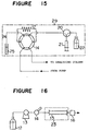
- Figure 16 is a diagram showing a typical example of a mechanical structure for HPLC wherein reference numeral 12 designates a solvent, 13 a liquid supply pump, 14 a sample injecting apparatus, 15 an analyzing column, 23 a column oven and 16 a detector. A sample is injected through the sample injecting apparatus along with a flow of solvent to be introduced into a flow path for HPLC. Then, the sample is separated in the analyzing column 15 and is fed into the detector in which the concentration of the sample is measured.
- a generally used polymer can be dissolved in a solvent at about 60°C. Accordingly, it is relatively easy to conduct analysis on a distribution of the molecular weight. However, it is difficult to dissolve polyolefin such as polyethylene or polypropylene in the solvent at about 60°C.
- a conventional technique proposes to add a high-boiling solvent such as o-dichlorobenzene (ODCB) or trichlorobenzene (TCB) and to heat it to about 150°C to dissolve whereby the analysis of a distribution of the molecular weight is conducted by GPC.
- a sample injecting means (a 6-port-switching valve) 14 including a sample 25, a sampling needle 24 and a sampling loop 17, a syringe 21 as a metering means and a cleaning liquid containing vessel 22 are arranged in an oven 29 so that they are kept in the same elevated temperature condition as the analyzing column.
- the apparatus comprises the sample injecting means 14 provided with the sampling needle and the sampling loop 17, the metering means 21 such as a syringe, the cleaning liquid containing vessel 22 and the oven 29 and so on as shown in Figure 15.
- the sampling needle and mechanically movable parts such as the syringe as a metering means for sucking a predetermined amount of liquid are kept under a temperature condition so as to assure reliable operations. Since movable mechanical parts perform a vertical movement, a lateral movement and a rotational movement, durability is apt to decrease under a high temperature condition with the result that a trouble such as a defective movement may occur.
- portions such as a sealing material which are in contact with liquid components such as the sample, the solvent, the cleaning liquid and so on are mainly composed of a fluoride resin such as polytetrafluoroethylene or the like from the viewpoints of solvent resistance and pressure resistance.
- the fluoride resin shows a remarkable reduction of strength under a high temperature condition such as 100°C or more whereby liquid leakage may take place.
- the cleaning liquid is heated to a high temperature so that the sampling needle stained with the sample liquid is washed while preventing the precipitation of the sample. Accordingly, a cleaning liquid containing vessel is placed in an oven to keep the cleaning liquid in the vessel under a high temperature condition in the same manner as the analyzing column. Under such high temperature condition, however, the cleaning liquid may evaporate to leak out of the apparatus.
- a liquid chromatograph apparatus comprising a first column and a second column which are connected through a switching means, the liquid chromatograph apparatus being characterized in that the switching means comprises a valve body capable of switching between two movable positions wherein a flow path for a solvent directing from the first column to the second column is formed in one of the two movable positions; a flow path for the solvent directing from the second column to the first column is formed in the other of the two movable positions, and the flow paths formed in the two movable positions are such that flowing directions of the solvent in the first column are opposite and flowing directions of the solvent in the second column are the same.
- the switching means is a two-position-switching valve having at least 8 ports.
- the switching means is formed by combining two or more two-position-switching valves each having at least 6 ports.
- the liquid chromatograph apparatus which further comprises a sample injecting apparatus including a sample injecting means provided with a sampling needle and a sampling loop, a first heat exchanger, a second heat exchanger, a metering means and a cleaning liquid containing vessel, wherein a portion of the sample injecting means excluding at least the sampling needle and the first heat exchanger are kept under the same temperature condition as the columns; at least the second heat exchanger, the metering means and the cleaning liquid containing vessel are kept at a temperature different from the temperature in that portion and the first heat exchanger; and the sample injecting means, the first heat exchanger, the second heat exchanger, the metering means and the cleaning liquid containing vessel are connected in series.
- the liquid chromatograph apparatus according to the fourth aspect, wherein the sample injecting means is a two-position-switching valve having 6 ports.
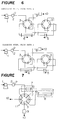
- Figure 1 shows schematically the liquid chromatograph apparatus according to the second aspect of the present invention, which is provided with a two-position-switching valve having 8 ports (hereinbelow, referred to as a 8-port-2-position-switching valve) as the switching means.
- reference numeral 1 designates a pump
- numeral 2 a sample injecting apparatus
- numeral 3 a 8-port-2-position-switching valve
- numeral 4 a filter
- numeral 5 a precolumn (a first column)
- numeral 6 an analyzing column
- numeral 9 a detector
- numeral 10 an outlet of waste solution.
- the precolumn and the analyzing column may respectively be housed in an oven 7 for precolumn and an oven 8 for analyzing column as shown in Figure 7.
- An upper portion of Figure 1 shows a flow path formed when analysis is conducted and a lower portion of Figure 1 shows a flow path formed when the precolumn is regenerated.
- the sample injecting apparatus shown in Figure 2 may have such structure described below.
- a flow path a port A of switching valve-a port H-the precolumn 5-a port C-a port B-the analyzing column 6-a port D-a port E-the detector 9, whereby the solvent is supplied successively through the precolumn (at a side A)-the precolumn (at a side B)-the analyzing column 6-the detector 9 in this order, during which impurities of the solvent and the sample and/or scraps of the sealing material for the pump and so on are deposited at an end (at a side A) of the precolumn 5.
- a switching operation is performed for the switching valve whereby there is formed a flow path: a port A of switching valve-a port B-the analyzing column 5-a port D-a port C-the precolumn 5-a port H-a port G.
- the solvent is supplied successively through the analyzing column 6-the precolumn (at a side B)-the precolumn (at a side A) to be discharged.
- the impurities of the solvent and the sample deposited at the end of the precolumn 5 (at a side A) and/or the scraps of the sealing material of the pump and so on are washed off by the solvent discharged out of the system. In this case, the washed-off impurities and so on are discharged out of the system without passing through the analyzing column 6, and accordingly, there is no danger of damaging the analyzing column.
- FIG. 2 shows in more detail the 8-port-2-position-switching valve shown in Figure 1.
- the switching valve is mainly constituted by a fixed face referred to as a stator and a working face referred to as a rotor.
- the rotor has through holes formed at equal angular intervals of 45°.
- the stator has grooves which are alternately formed at equal angular intervals of 45°.
- Figure 2 shows the stator and the rotor in a separated state in order to clarify the structure of the switching valve. In fact, however, the both members are in close contact with each other and flowing paths are formed by rotating the rotor by 45°.
- Figure 3 is a diagram showing directions of solvent flowing in the precolumn (the first column).
- the solvent flows in a direction of analyzing column 6.
- the solvent flows in the direction opposite to the case of analyzing.
- the solvent is always passed in a constant direction irrespective of analyzing or regenerating. Namely, although two ways of solvent flow path are formed depending on movable positions by operating the switching valve, the flowing directions of the solvent are opposite to each other in the first column while the flowing directions of the solvent are the same in the second column.
- Figure 4 is a diagram for explaining a case that the precolumn is exchanged.
- the precolumn can easily be regenerated to thereby minimize the necessity of exchange. However, these are also effective even in a case of exchanging the precolumn.
- the exchange of the precolumn should be conducted by stopping the liquid supplying operation of the pump (as shown in a left side in Figure 4). The stop of the liquid supply is essential because the precolumn is connected in series to the analyzing column. After the precolumn has been exchanged, it is necessary to conduct equilibration of the interior of the columns and the detector by restarting liquid supply by the pump.
- a new precolumn is filled with a solvent (a preserving solvent) other than the solvent used for analyzing. After the exchange, it is gradually substituted with the solvent used for analyzing. Since the preserving solvent flows successively through the precolumn, the analyzing column and the detector, the equilibrium of the analyzing column which was in a stable state is once lost. Further, since a temperature of the new column is different from that of the analyzing column, equilibrium of temperature is also lost. Thus, after the precolumn has been exchanged, it takes a much time to obtain a state of equilibrium.
- a solvent a preserving solvent
- the exchange of the precolumn and the equilibrating operation of the precolumn can be performed in a shorter time by switching the valve (as shown in a right side of Figure 4).
- the flow path used for regenerating the precolumn is used.
- the preserving solvent in the new precolumn is discharged directly out of the system without being introduced into the analyzing column.
- the switching operation is conducted to form the flow path usable for analyzing whereby an analyzing operation can be restarted in a shorter time. In this case, it is unnecessary to stop the liquid supply by the pump during the exchange of the precolumn.
- the liquid chromatograph apparatus with the 8-port-2-position-switching valve according to the second aspect of the present invention
- the liquid chromatograph apparatus may be provided with a switching valve having more than 8 ports.
- needless ports may be plugged or a bypass may be formed so that substantially the same flow path as the above-mentioned embodiment can be formed.
- the same flow paths can be formed by bypassing the flow path between ports F and G as shown in Figure 5.
- an outlet of waste solution used for analyzing and an outlet of waste solution used for regeneration are commonly used.
- the same flow paths as described above can be formed by combining a plurality of switching valves having at least 6 ports.
- Figure 6 shows an embodiment of the liquid chromatograph apparatus according to the third aspect of the present invention wherein two switching valves having 6 ports are used in combination.
- the first column and/or the second column may be a group of columns connected in series.
- the liquid chromatograph apparatus comprises, in addition to the elements as described in the first aspect, a sample injecting apparatus including a sample injecting means provided with a sampling needle and a sampling loop, a first heat exchanger, a second heat exchanger, a metering means and a cleaning liquid containing vessel, wherein a portion of the sample injecting means excluding at least the sampling needle and the first heat exchanger are kept under the same temperature condition as the columns; at least the second heat exchanger, the metering means and the cleaning liquid containing vessel are kept at a temperature different from the temperature in that portion and the first heat exchanger; and the sample injecting means, the first heat exchanger, the second heat exchanger, the metering means and the cleaning liquid containing vessel are connected in series.
- the sample injecting apparatus is suitable for conducting high temperature HPLC by which a sample is analyzed under a high temperature condition, and the sample injecting apparatus itself can provide a sufficient effect without being added to the liquid chromatograph apparatus.
- a preferably high temperature HPLC apparatus can be provided.
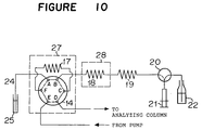
- FIG 10 shows an embodiment of the sample injecting apparatus incorporated in the liquid chromatograph apparatus according to the fifth aspect of the present invention.
- reference numeral 24 designates a sampling needle
- numeral 14 a sample injecting means (a 6-port-switching valve)
- numeral 17 a sampling loop
- numerals 27 and 28 designate ovens which keep the sample injecting means 14 including the sampling loop 17 and a preheating loop (the first heat exchanger) 18 under the same temperature condition as the analyzing column (not shown)
- numeral 19 a cooling loop (the second heat exchanger)
- numeral 20 a switching valve
- numeral 21 a metering means (syringe)
- numeral 22 a cleaning liquid including vessel.
- the sampling needle 24 is driven in XYZ directions by a needle driving means (not shown) to be immersed in a sample 25.
- a cleaning liquid in the vessel 22 may be the same solvent as the solvent supplied from the liquid supply pump (not shown).
- the above-mentioned analyzing apparatus in which the first column and the second column are connected by means of the switching valve, is connected to a port D in the 6-port-switching valve. More specifically, a port A in the 8-port-switching valve in Figure 1 is connected to the port D in this embodiment. On the other hand, a port E is connected to the liquid supply pump 1 shown in Figure 1.
- the sampling loop 17 in this embodiment is of a spirally wound pipe, the capacity of which is determined depending on an amount of the sample supplied for analyzing.
- the preheating loop 18 as the first heat exchanger and the cooling loop 19 as the second heat exchanger are both of spirally wound pipes and of a type capable of heat-exchanging when the liquid is passed through these loops.
- the first heat exchanger 18 is housed in the oven 28 so as to be under a high temperature condition whereby the liquid in the heat exchanger is elevated to a predetermined temperature.
- the second heat exchanger 19 is, in a case of this embodiment, under a room temperature condition whereby the liquid in the second heat exchanger is brought to the room temperature.
- the second heat exchanger 19 may be housed in a cooling box other than being placed under the room temperature condition. However, determination as to whether or not the cooling box or the like is used is suitably made in consideration of temperature conditions for the syringe 21 and the cleaning liquid 22.
- the sample injecting means 14 including the sampling loop 17 and the preheating loop (the first heat exchanger) 18 are respectively housed in the ovens 27, 28 separately. However, they may be disposed in the same oven.
- the oven or ovens can be one or ones usable for the ordinary HPCL. Temperature in the ovens is controlled to be under the same temperature condition as that in the analyzing means comprising the analyzing column and so on (e.g., the precolumn, the analyzing column, the switching valve and detector in the first to third aspects of the present invention) whereby deposition of the sample can be prevented.
- the liquid chromatograph apparatus is suitably usable for high temperature HPLC wherein the sample dissolved under a high temperature condition is analyzed by an analyzing means such as the analyzing column.
- an analyzing means such as the analyzing column.
- GPC is conducted for the before-mentioned polyolefin or the like (in this case, the sample should be heated to about 150°C).
- the needle in the sample injecting means, the metering means and the cleaning liquid containing vessel can be subjected to a temperature different from the temperature condition for the sample, e.g., under the room temperature condition, whereby problems such as a defective movement of mechanical elements or the evaporation of the cleaning liquid can be prevented.
- the first heat exchanger can be used as a cooling loop while the second heat exchanger is for a heating loop.
- Figure 10 shows an example of using the 6-port-switching valve as the sample injecting means.
- the present invention is not limited thereto and a 8-port-switching valve can be used, for example.
- the switching valve 20 in Figure 10 may be such one as to be used for the ordinary HPLC, e.g. an electromagnetic valve or the like.
- the syringe pump as a metering means may be substituted with another liquid supply means.
- FIG 11 shows in detail the 6-port-switching valve which is suitable as the sample injecting means 14.
- the 6-port-switching valve is also constituted by a fixed face referred to as a stator and a working face referred to as a rotor in the same manner as the 8-port-switching valve shown in Figure 2.
- the stator has through holes formed at angular intervals of 60° and the rotor has three grooves formed at angular intervals of 60° in a triangular form.
- the stator and the rotor are in close contact with each other to form flow paths.
- two kinds of flow path By turning the rotor by 60°, two kinds of flow path: a flow path 1 and a flow path 2, can be formed.
- the reference numerals in Figure 11 are the same as those of Figure 10.
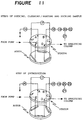
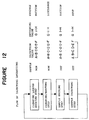
- Sample injecting operations by the sample injecting apparatus shown in Figure 10 comprises four steps: a cleaning liquid sucking step, a cleaning/heating step, a sample sucking step and a sample injecting step.
- Figure 12 shows a flow chart of these steps, and Figure 13 shows actual operations of the sample injecting apparatus.
- the cleaning liquid sucking step is conducted by using a flow path shown in Figure 13a.
- the sample injecting means (6-port-switching valve) 14 is in a state that ports A-B, C-D and E-F are respectively communicated, and the switching valve 20 is in a state that ports I-H are communicated.
- the metering means (syringe) 21 is operated (by pulling the plunger) to inject the cleaning liquid kept at the room temperature into the sample injecting means 14.
- a flow path shown in Figure 13b is used.
- the sample injecting means (6-port-switching valve) is in a state that ports A-B, C-D and E-F are respectively communicated, and the switching valve 20 is in a state that ports I-G are communicated.
- the metering means (syringe) 21 is operated by pushing the plunger, whereby the cleaning liquid 22 in the sample injecting means is discharged through the sampling needle 24 via the second heat exchanger (cooling loop) 19, the first heat exchanger (preheating loop) 18 and the sample injecting means 14.
- the cleaning liquid 22 is heated to the same temperature as in the analyzing column while it is passed through the first heat exchanger (preheating loop) 18 in the oven 23 which is controlled to have the same temperature condition as the analyzing column.
- the cleaning liquid is heated finally to the same temperature as the analyzing column, namely a temperature capable of dissolving the sample, and then, the cleaning liquid is discharged through the sampling needle 24.
- the sampling needle 24 is kept under a room temperature condition and the cleaning liquid of high temperature can be passed therethrough. Even in a case of conducting the analyzing repeatedly, the needle 24 can be washed off without a danger that the sample in the last sample sucking operation is deposited on the needle 24.
- the sample sucking step is conducted by using a flow path shown in Figure 13c.
- the sample injecting means (6-port-switching valve) 14 is in a state that ports A-B, C-D and E-F are respectively communicated, and the switching valve 20 is in a state that ports I-G are communicated.
- the sample 25 dissolved at a high temperature is placed below the sampling needle 24, and then, the needle 24 is descended into the sample.
- the metering means (syringe) 21 is operated by pulling the plunger so that the sampling loop 17 is filled with the sample 25.
- the cleaning liquid remaining in the sampling loop 17 and the first heat exchanger (preheating loop) 18 is passed through the second heat exchanger (cooling loop) 19 to be returned to the metering means (syringe) 21. Since the cleaning liquid in the sampling loop 17 and the first heat exchanger (preheating loop) 18 is under a high temperature condition by means of the oven 23, it is kept at substantially the same temperature as the analyzing column. Then, the temperature of the cleaning liquid is decreased during being passed through the second heat exchanger (cooling loop) 19 before it is returned to the metering means (syringe) 21.
- the sample injecting step is conducted by using a flow path shown in Figure 13d.
- the sample injection means (6-port-switching valve) 14 is in a state that ports B-C, D-E and F-A are respectively communicated, and the sample introduced into the sampling loop 17 is supplied to the analyzing column in which separation and detection are carried out.
- sample injecting apparatus having the structure shown in Figure 10 makes it unnecessary to place the sampling needle and the metering means having a movable mechanical parts under a high temperature condition even in HPLC for analyzing the sample under a high temperature condition. Further, since it is unnecessary to place the cleaning liquid under a high temperature condition, the evaporation of the cleaning liquid and the leakage of it outside of the apparatus can be prevented. Accordingly, when the sample injecting apparatus is combined with the structure according to the first to third aspects of the present invention in which the precolumn and the analyzing column are connected through the switching valve, double effects of easiness of regenerating the precolumn and being applicable suitably to high temperature HPLC can be achieved.
- the standard polystyrene was used as a sample; the amount of the sample injected was 300 ⁇ l and the amount of liquid supplied from the pump was 1 ml/min.
- the precolumn used was a commercially available column (tradename: TSKgel GMH manufactured by TOSOH CORPORATION, 7.8 mm (inner diameter) ⁇ 3 cm (length)).
- the analyzing column used was three commercially available analyzing columns connected in series (tradename: TSKgel GMH manufactured by TOSOH CORPORATION, 7.8 mm (inner diameter) ⁇ 30 cm (length)). Ovens 7 and 8 for housing these columns were controlled to be at 50°C. These columns were previously used for analyzing standard polystyrene for a long term prior to measuring the pressure of the pump.
- Figure 8 is a diagram showing a change of pressure in the pump in switching operations of the valve.
- a zone A shows a pressure change in an analyzing operation
- a zone B shows a pressure change when the flow path for analyzing operation is switched to the flow path for regeneration
- a zone C shows a pressure change when the flow path for regeneration is again switched to the flow path for analyzing.
- the sample injecting apparatus shown in Figure 10 was applied to the high temperature GPC.
- the conditions for the high temperature GPC were as follows. ODCB was used as the solvent (cleaning liquid) 22; polyethylene was used as the sample 25 to be analyzed; and the capacity of the metering means (syringe pump) 21 was 1 ml.
- the sample was dissolved in the solvent which was heated to 150°C, and temperature in the ovens 27 and 28 was set to 150°C.
- An amount of the sample to be analyzed was 300 ⁇ l, and accordingly, the capacity of the sampling loop 17 was 300 ⁇ l.
- the capacities of the first heat exchanger (preheating loop) 18 and the second heat exchanger (cooling loop) 19 were respectively 2 ml so as to obtain sufficient heat exchange.
- An amount of the liquid supplied from the pump (not shown) was 1 ml/min.
- a serial connection of commercially available analyzed columns (three columns connected in series, tradename: TSKgel GMH manufactured by TOSOH CORPORATION, each 7.8 mm (inner diameter) ⁇ 30 cm (length)), the three columns being housed in an oven which was temperature-controlled to be about 150°C and a commercially available refractometer is connected to a port D. No precolumn was connected.
- the sample injecting means 14 was brought into a state that ports A-B, C-D and E-F were communicated, and the switching valve 20 was brought into a state that ports I-H were communicated, and then, the cleaning liquid sucking step was conducted. Namely, the plunger of the syringe 21 was pulled to fill the 1 ml syringe with the cleaning liquid 22.
- the sample injecting means 14 was brought into a state that ports A-B, C-D and E-F were communicated and the switching valve 20 was brought into a state that ports I-G were communicated, and then, the cleaning/heating step was conducted. Namely, the plunger of the syringe 21 was pushed to discharge the cleaning liquid in an amount of 1 ml through the sampling needle 24 while the cleaning liquid was heated during which the analyzing columns is washed and the sampling needle is heated.
- the sample injecting means 14 was brought into a state that ports A-B, C-D and E-F were communicated, and the switching valve was brought to a state that ports I-G were communicated, and the sample sucking step was conducted. Namely, the dissolved sample 25 was placed below the sampling needle 24, and the needle 24 was descended into the sample. Then, the plunger of the syringe 21 was pulled to suck the sample by an amount of 0.5 ml to fill the sample in the sampling loop 17.
- the sample injecting means 14 was brought into a state that ports B-C, D-E and F-A were communicated, and an amount of 300 ⁇ l of the sample in the sampling loop 17 was introduced into the analyzing column (not shown). After the sample was injected, the cleaning liquid sucking step and cleaning/heating step were conducted to wash off the sample remaining in the sampling needle.
- Figure 14 shows a result of the analysis wherein symbol a indicates a signal of the refractometer, symbol b indicates the pressure of the pump, and the symbol c indicates the time of starting injection of the sample. Deposition of the injected sample in the flow path frequently cause clogging of the flow path to result a pressure increase and a large disturbance of signal in the refractometer. However, in the apparatus shown in Figure 10, there was no found an increase of pressure in the pump and a disturbance of signal in the detector whereby a preferred chromatogram was obtainable.
- the regeneration of the precolumn is possible without detaching the precolumn. Accordingly, since the work for detaching the precolumn is unnecessary, the regenerating treatment can quickly, easily be conducted with the result that interruption of analysis can be short. Further, the quick, easy regeneration of the precolumn can reduce the occurrence of a pressure increase of pump due to the deposition of scraps on the precolumn.
- the washing-off and regeneration of the precolumn can be conducted by using only the solvent for analyzing without using the solvent for regeneration. Further, use of a single pump is enough to supply the liquid in the regeneration.
- the same kind of solvent can be introduced into the first column and the second column to regenerate the precolumn. Accordingly, there is no problem that it takes a longer time to equilibrate the analyzing column after the regeneration. Even in HPLC in a mode other than GPC, the same kind of solvent can be supplied to the first column and the second column irrespective of analyzing or regenerating.
- the metering means, the cleaning liquid and so on under a different temperature condition, normally, under a room temperature condition from that for the analyzing column, by placing only minimum necessary mechanical elements under the same temperature condition as the analyzing column. Accordingly, occurrence of a defective movement of the mechanical elements in the sample injecting apparatus can be minimized. Further, since an element (such as a sealing material) used in a portion in contact with the sample or the solvent and so on is disposed under a room temperature condition, a danger of decreasing its strength can be minimized.
- the sample injecting apparatus is suitable as an apparatus for injecting the sample into the analyzing column under a high temperature condition of exceeding 100°C.
- the liquid chromatograph apparatus provided with the sample injecting apparatus according to the fourth and fifth aspects can provide quick, easy regeneration of the precolumn and minimizes occurrence of a defective operation of the mechanical elements in the sample injecting apparatus.
- the liquid chromatograph apparatus is suitable for high temperature HPLC.
Landscapes
- Physics & Mathematics (AREA)
- Health & Medical Sciences (AREA)
- Life Sciences & Earth Sciences (AREA)
- Chemical & Material Sciences (AREA)
- Analytical Chemistry (AREA)
- Biochemistry (AREA)
- General Health & Medical Sciences (AREA)
- General Physics & Mathematics (AREA)
- Immunology (AREA)
- Pathology (AREA)
- Sampling And Sample Adjustment (AREA)
- Treatment Of Liquids With Adsorbents In General (AREA)
Applications Claiming Priority (5)
| Application Number | Priority Date | Filing Date | Title |
|---|---|---|---|
| JP189827/97 | 1997-07-15 | ||
| JP18982797A JP3673884B2 (ja) | 1997-07-15 | 1997-07-15 | 切り替え弁を用いた液体クロマトグラフ |
| JP19853097A JP3673885B2 (ja) | 1997-07-24 | 1997-07-24 | 液体クロマトグラフィにおける試料注入装置 |
| JP198530/97 | 1997-07-24 | ||
| US09/114,497 US5958227A (en) | 1997-07-15 | 1998-07-13 | Liquid chromatograph apparatus with a switching valve |
Publications (1)
| Publication Number | Publication Date |
|---|---|
| EP0892267A1 true EP0892267A1 (de) | 1999-01-20 |
Family
ID=27326231
Family Applications (1)
| Application Number | Title | Priority Date | Filing Date |
|---|---|---|---|
| EP98113110A Withdrawn EP0892267A1 (de) | 1997-07-15 | 1998-07-14 | Flüssigkeitschromatograph mit Schaltventil |
Country Status (2)
| Country | Link |
|---|---|
| US (1) | US5958227A (de) |
| EP (1) | EP0892267A1 (de) |
Cited By (9)
| Publication number | Priority date | Publication date | Assignee | Title |
|---|---|---|---|---|
| WO2001090722A1 (fr) * | 2000-05-23 | 2001-11-29 | Hocer | Installation et procede pour la preparation automatique d'echantillons |
| EP1288656A2 (de) * | 2001-09-03 | 2003-03-05 | Shiseido Company, Ltd. | Flüssigchromatographiesystem und Probenaufgeber sowie Reinigungsvorrichtung und Reinigungsverfahren |
| US7526947B2 (en) * | 2005-03-02 | 2009-05-05 | Shimadzu Corporation | Automatic sample introduction apparatus |
| EP2343549A1 (de) * | 2008-10-03 | 2011-07-13 | Arkray, Inc. | Analysevorrichtung und verfahren zu ihrer steuerung |
| CN108152334A (zh) * | 2017-11-17 | 2018-06-12 | 海南核电有限公司 | 一种移动式阴阳离子分析装置 |
| EP3396372A1 (de) * | 2017-04-26 | 2018-10-31 | Watrex Praha, s.r.o. | Vorrichtung und verfahren zur rückführung von flüssigkeiten mit zwei 2-wegeventilen |
| EP2667188B1 (de) * | 2012-05-25 | 2021-06-23 | Manol Roussev | Trennsäulenofen |
| US11630091B2 (en) | 2020-05-14 | 2023-04-18 | Lg Chem, Ltd. | On-line system for improving detection level of analytes by liquid chromatography and analysis method using same |
| WO2023219845A1 (en) * | 2022-05-09 | 2023-11-16 | Waters Technologies Corporation | Fluidic network for aseptic sampling |
Families Citing this family (18)
| Publication number | Priority date | Publication date | Assignee | Title |
|---|---|---|---|---|
| US6136197A (en) * | 1998-05-27 | 2000-10-24 | Battelle Memorial Institute | Systems for column-based separations, methods of forming packed columns, and methods of purifying sample components |
| DE19926163B4 (de) * | 1998-06-19 | 2008-07-03 | Shimadzu Corp. | Flüssigchromatograph |
| JP3476417B2 (ja) * | 2000-06-05 | 2003-12-10 | 株式会社島津製作所 | 液体クロマトグラフによる分析方法 |
| US7316769B2 (en) * | 2001-03-19 | 2008-01-08 | Cornell Research Foundation, Inc. | Length-dependent recoil separation of long molecules |
| DE10301601B3 (de) * | 2003-01-16 | 2004-08-12 | Sls Micro Technology Gmbh | Miniaturisierter Gaschromatograph und Injektor hierfür |
| JP3816883B2 (ja) * | 2003-03-06 | 2006-08-30 | 株式会社日立ハイテクノロジーズ | 液体クロマトグラフ質量分析装置 |
| JP3823092B2 (ja) * | 2003-03-11 | 2006-09-20 | 株式会社日立ハイテクノロジーズ | 分離分析装置 |
| DE102005025440B4 (de) | 2005-06-02 | 2018-04-05 | Waters Gmbh | System und Verfahren zur Probenvorbereitung |
| WO2007001984A2 (en) | 2005-06-21 | 2007-01-04 | Waters Investments Limited | Apparatus and methods for performing steps of a multi-step process in parallel |
| WO2010083147A1 (en) * | 2009-01-14 | 2010-07-22 | Waters Technologies Corporation | Rotating valve |
| JP2012117945A (ja) * | 2010-12-02 | 2012-06-21 | Hitachi High-Technologies Corp | 液体クロマトグラフ,液体クロマトグラフ用試料導入装置、および液体クロマトグラフ用試料導入装置の洗浄方法 |
| US9546986B2 (en) * | 2011-08-19 | 2017-01-17 | Waters Technologies Corporation | Column manager with a multi-zone thermal system for use in liquid chromatography |
| EP3234587B1 (de) * | 2014-12-15 | 2021-01-27 | Cytiva Sweden AB | Drehventile und systeme |
| CA3028243C (en) * | 2017-01-13 | 2022-11-29 | Van So Le | Alternating flow column chromatography apparatus and method of use |
| CN111902196A (zh) * | 2018-03-29 | 2020-11-06 | 沃特世科技公司 | 用于解决具有挑战性的分离问题的自动化双柱循环色谱方法 |
| JP7303723B2 (ja) * | 2019-10-17 | 2023-07-05 | 株式会社日立ハイテク | 流路切替バルブシステムおよび液体クロマトグラフ |
| CN115087866A (zh) * | 2020-02-21 | 2022-09-20 | 株式会社岛津制作所 | 液相色谱仪 |
| US11733218B2 (en) * | 2021-09-08 | 2023-08-22 | Dionex Corporation | Automated valve switching setup for ion chromatography (IC) that facilitates equilibration of consumables or allows for normal IC operation |
Citations (7)
| Publication number | Priority date | Publication date | Assignee | Title |
|---|---|---|---|---|
| US4017262A (en) * | 1973-08-06 | 1977-04-12 | The Dow Chemical Company | Chromatographic apparatus for analysis of ionic species |
| US4452067A (en) * | 1982-08-30 | 1984-06-05 | The Dow Chemical Company | Apparatus for analysis of a vapor phase sample |
| US4567753A (en) * | 1984-12-12 | 1986-02-04 | The Dow Chemical Company | Independent analysis of anions and cations using indirect photometric chromatography |
| US4577492A (en) * | 1983-05-12 | 1986-03-25 | Phillips Petroleum Company | Analytical method and apparatus |
| EP0230307A2 (de) * | 1986-01-21 | 1987-07-29 | Millipore Corporation | Verfahren und Vorrichtung für die Ionenchromatographie |
| EP0359322A2 (de) * | 1988-09-16 | 1990-03-21 | Koninklijke Philips Electronics N.V. | Flüssigchromatographie |
| US5567307A (en) * | 1994-09-30 | 1996-10-22 | Lachat Instruments | System and a method for using a small suppressor column in performing liquid chromatography |
Family Cites Families (3)
| Publication number | Priority date | Publication date | Assignee | Title |
|---|---|---|---|---|
| US5071547A (en) * | 1990-03-23 | 1991-12-10 | Separations Technology, Inc. | Column chromatographic column apparatus with switching capability |
| US5547497A (en) * | 1992-09-30 | 1996-08-20 | Chromatofast, Inc. | Apparatus for gas chromatography |
| DE69601035T2 (de) * | 1995-03-03 | 1999-04-15 | Microsensor Technology, Inc., Fremont, Calif. | Festvolumeninjektor mit rückspülfähigkeit |
-
1998
- 1998-07-13 US US09/114,497 patent/US5958227A/en not_active Expired - Fee Related
- 1998-07-14 EP EP98113110A patent/EP0892267A1/de not_active Withdrawn
Patent Citations (7)
| Publication number | Priority date | Publication date | Assignee | Title |
|---|---|---|---|---|
| US4017262A (en) * | 1973-08-06 | 1977-04-12 | The Dow Chemical Company | Chromatographic apparatus for analysis of ionic species |
| US4452067A (en) * | 1982-08-30 | 1984-06-05 | The Dow Chemical Company | Apparatus for analysis of a vapor phase sample |
| US4577492A (en) * | 1983-05-12 | 1986-03-25 | Phillips Petroleum Company | Analytical method and apparatus |
| US4567753A (en) * | 1984-12-12 | 1986-02-04 | The Dow Chemical Company | Independent analysis of anions and cations using indirect photometric chromatography |
| EP0230307A2 (de) * | 1986-01-21 | 1987-07-29 | Millipore Corporation | Verfahren und Vorrichtung für die Ionenchromatographie |
| EP0359322A2 (de) * | 1988-09-16 | 1990-03-21 | Koninklijke Philips Electronics N.V. | Flüssigchromatographie |
| US5567307A (en) * | 1994-09-30 | 1996-10-22 | Lachat Instruments | System and a method for using a small suppressor column in performing liquid chromatography |
Cited By (16)
| Publication number | Priority date | Publication date | Assignee | Title |
|---|---|---|---|---|
| WO2001090722A1 (fr) * | 2000-05-23 | 2001-11-29 | Hocer | Installation et procede pour la preparation automatique d'echantillons |
| FR2809490A1 (fr) * | 2000-05-23 | 2001-11-30 | Hocer | Installation et procede pour la preparation automatique d'echantillons |
| US7517698B2 (en) | 2000-05-23 | 2009-04-14 | Hocer | Installation and process for automatic preparation of samples |
| EP1288656A2 (de) * | 2001-09-03 | 2003-03-05 | Shiseido Company, Ltd. | Flüssigchromatographiesystem und Probenaufgeber sowie Reinigungsvorrichtung und Reinigungsverfahren |
| EP1288656A3 (de) * | 2001-09-03 | 2004-07-14 | Shiseido Company, Ltd. | Flüssigchromatographiesystem und Probenaufgeber sowie Reinigungsvorrichtung und Reinigungsverfahren |
| US7526947B2 (en) * | 2005-03-02 | 2009-05-05 | Shimadzu Corporation | Automatic sample introduction apparatus |
| EP2343549A4 (de) * | 2008-10-03 | 2012-04-04 | Arkray Inc | Analysevorrichtung und verfahren zu ihrer steuerung |
| CN102171560A (zh) * | 2008-10-03 | 2011-08-31 | 爱科来株式会社 | 分析装置及其控制方法 |
| EP2343549A1 (de) * | 2008-10-03 | 2011-07-13 | Arkray, Inc. | Analysevorrichtung und verfahren zu ihrer steuerung |
| CN102171560B (zh) * | 2008-10-03 | 2014-06-04 | 爱科来株式会社 | 分析装置及其控制方法 |
| US8939018B2 (en) | 2008-10-03 | 2015-01-27 | Arkray, Inc. | Analyzing device and method for controlling same |
| EP2667188B1 (de) * | 2012-05-25 | 2021-06-23 | Manol Roussev | Trennsäulenofen |
| EP3396372A1 (de) * | 2017-04-26 | 2018-10-31 | Watrex Praha, s.r.o. | Vorrichtung und verfahren zur rückführung von flüssigkeiten mit zwei 2-wegeventilen |
| CN108152334A (zh) * | 2017-11-17 | 2018-06-12 | 海南核电有限公司 | 一种移动式阴阳离子分析装置 |
| US11630091B2 (en) | 2020-05-14 | 2023-04-18 | Lg Chem, Ltd. | On-line system for improving detection level of analytes by liquid chromatography and analysis method using same |
| WO2023219845A1 (en) * | 2022-05-09 | 2023-11-16 | Waters Technologies Corporation | Fluidic network for aseptic sampling |
Also Published As
| Publication number | Publication date |
|---|---|
| US5958227A (en) | 1999-09-28 |
Similar Documents
| Publication | Publication Date | Title |
|---|---|---|
| US5958227A (en) | Liquid chromatograph apparatus with a switching valve | |
| CN107449852B (zh) | 以对源流路小影响的方式对流体样品分流 | |
| US8968561B2 (en) | Preparative separation/purification system | |
| US20130067997A1 (en) | Single injection valve for hplc combining sample introduction, wash cycles and diagnosis | |
| US20160274069A1 (en) | Autosampler and liquid chromatograph | |
| JP4228502B2 (ja) | 液体クロマトグラフ及び流路切替バルブ | |
| WO2016089515A1 (en) | System and method for performing a chromatography injection sequence using a single injection valve | |
| JP2004271409A (ja) | 分離分析装置 | |
| CN112295265A (zh) | 具有流体样品容留的样品分配 | |
| US20210123892A1 (en) | Liquid chromatograph including passage switch valve | |
| JP6711188B2 (ja) | サプレッサーを切り替えるイオンクロマトグラフ | |
| JPH06201650A (ja) | 高速液体クロマトグラフ・質量分析計の直結方法およびその装置 | |
| WO2023242303A1 (en) | Sample preparation system and method for preparing a sample using the sample preparation system | |
| EP0309380B1 (de) | Umlaufchromatograph mit überkritischem Fluid | |
| CA2342636C (en) | Chromatographic separator | |
| JPH1137985A (ja) | 切り替え弁を用いた液体クロマトグラフ | |
| CN114929364B (zh) | 有机溶剂回收系统 | |
| JP2004077329A (ja) | クロマト分離装置 | |
| WO2022112911A1 (en) | Testing a sampling unit fluidically coupled to a source | |
| JP3673885B2 (ja) | 液体クロマトグラフィにおける試料注入装置 | |
| WO2023106033A1 (ja) | 液体クロマトグラフの制御方法 | |
| JPH07275601A (ja) | 固相抽出カラム再生機能付き自動固相抽出装置 | |
| JP2001133445A (ja) | 液体クロマトグラフ | |
| WO2020183663A1 (ja) | クロマトグラフ用オートサンプラ | |
| US20200011841A1 (en) | Parallel Separation and Washing in Size Exclusion Chromatography Separation or in Desalting of a Target from a Sample |
Legal Events
| Date | Code | Title | Description |
|---|---|---|---|
| PUAI | Public reference made under article 153(3) epc to a published international application that has entered the european phase |
Free format text: ORIGINAL CODE: 0009012 |
|
| AK | Designated contracting states |
Kind code of ref document: A1 Designated state(s): DE FR GB |
|
| AX | Request for extension of the european patent |
Free format text: AL;LT;LV;MK;RO;SI |
|
| 17P | Request for examination filed |
Effective date: 19990527 |
|
| AKX | Designation fees paid |
Free format text: DE FR GB |
|
| 17Q | First examination report despatched |
Effective date: 20070306 |
|
| STAA | Information on the status of an ep patent application or granted ep patent |
Free format text: STATUS: THE APPLICATION IS DEEMED TO BE WITHDRAWN |
|
| 18D | Application deemed to be withdrawn |
Effective date: 20070717 |