EP0892249B1 - Dispositif de mesure - Google Patents
Dispositif de mesure Download PDFInfo
- Publication number
- EP0892249B1 EP0892249B1 EP98110899A EP98110899A EP0892249B1 EP 0892249 B1 EP0892249 B1 EP 0892249B1 EP 98110899 A EP98110899 A EP 98110899A EP 98110899 A EP98110899 A EP 98110899A EP 0892249 B1 EP0892249 B1 EP 0892249B1
- Authority
- EP
- European Patent Office
- Prior art keywords
- sensor
- sensor assembly
- data
- assembly
- measuring arrangement
- Prior art date
- Legal status (The legal status is an assumption and is not a legal conclusion. Google has not performed a legal analysis and makes no representation as to the accuracy of the status listed.)
- Expired - Lifetime
Links
Images

Classifications
-
- G—PHYSICS
- G01—MEASURING; TESTING
- G01D—MEASURING NOT SPECIALLY ADAPTED FOR A SPECIFIC VARIABLE; ARRANGEMENTS FOR MEASURING TWO OR MORE VARIABLES NOT COVERED IN A SINGLE OTHER SUBCLASS; TARIFF METERING APPARATUS; MEASURING OR TESTING NOT OTHERWISE PROVIDED FOR
- G01D3/00—Indicating or recording apparatus with provision for the special purposes referred to in the subgroups
- G01D3/02—Indicating or recording apparatus with provision for the special purposes referred to in the subgroups with provision for altering or correcting the law of variation
- G01D3/022—Indicating or recording apparatus with provision for the special purposes referred to in the subgroups with provision for altering or correcting the law of variation having an ideal characteristic, map or correction data stored in a digital memory
Definitions
- Measuring arrangements of this type make it possible to measure the sensor signals digitize in the sensor assembly as close as possible to the sensor and further processing, such as compensation and Implementation of the measurement results in a suitable one for the output Form, in the evaluation module separated from the sensor module make.
- This increases the immunity to interference and signal stability of the measuring arrangement.
- the storage of sample-dependent sensor characteristics, such as sensitivity and temperature coefficient, in a non-volatile digital memory directly at the sensor makes it easier for the manufacturer by having ready-made calibrated sensor and Evaluation modules for a variety of measuring ranges and Approval options to keep delivery times short. About that In addition, repairs or measuring range conversions at Quickly performed by users without renewed factory calibration become.
- the object of the invention is to provide a measuring arrangement of the type specified above, which is a simple exchange the sensor module without changing the evaluation module enables and in which a voltage-free galvanic Separation between sensor module and evaluation module possible in a simple manner and with little effort is.
- the sensor module is initialized without any action the evaluation module due to that in the sensor module saved configuration data. Similarly are those for data processing in the evaluation module required sensor-specific data and the data required for this required program code and in the further course the Processing measurement data without request from the evaluation module from the sensor module to the evaluation module transferred so that data transfers only in the Direction from the sensor module to the evaluation module respectively. That is why the digital interface is between the two modules a unidirectional serial Interface that is easily a galvanic Separation allowed. Only in the opposite direction Power supply of the sensor module from the evaluation module as well as the transfer of a Clock signal; these one-sided connections can be also easily galvanically separate.
- Measuring arrangement are in the subclaims characterized.
- the measuring arrangement shown in Fig. 1 of the drawing contains a sensor assembly 10 which is used to detect physical measurands. It contains for this purpose For each measured variable to be recorded, one sensor, the one provides analog electrical output signal from that Value of the measured variable is dependent.
- a pressure transmitter that one Includes pressure sensor 12 and a temperature sensor 13 because Usually the temperature of the pressure sensor is also measured and for example for compensation and / or for calibration is used.
- the analog output signal from the pressure sensor 12 is via a sensor interface circuit 14, which for Adaptation of the sensor serves an analog-digital converter 15 fed by digitizing it. In the same way becomes the analog output signal of the temperature sensor 13 an analog-digital converter via a sensor interface circuit 16 17 supplied and digitized in this.
- the analog-digital converters 15 and 17 deliver to their Outputs digitized measurement data, the recorded pressure or indicate the recorded temperature.
- the sensor adjustment through the sensor interface circuits 14, 16 and Digitization of the measurement data in the analog-digital converters 15 and 17 depends on sensor-specific Configuration data stored in configuration registers 18 stand.
- the sensor module 10 also contains a status circuit 19, which outputs a digital status signal that the shows the respective status of the sensor module.
- the measuring arrangement also contains an evaluation module 20, in which the digitized delivered by the sensor assembly 10 Measurement data are processed.
- the evaluation module 20 can be spatially separated from the sensor assembly and is connected to it via an interface 22, via the digitized measurement data and the digital status signal from sensor assembly 10 to evaluation assembly 20 be transmitted.
- the evaluation module contains a data processing device 24 with a processor 25, one Program memory 26 and a data memory 27.
- the data processing serves to correct the measurement data depending on on the characteristics of the individual used Sensors.
- the processed measurement data can, for example in a conventional manner by a digital-to-analog converter 28 be converted into an analog measurement signal, which via a Two-wire line 29 is transmitted to a control center 30 in which displays the measurement result or uses it in some other way becomes.
- the analog measurement signal can be according to a conventional Norm, for example, a variable between 4 and 20 mA Be electricity.
- the evaluation module 20 also contains a power supply circuit 32, which for the operation of the measuring arrangement required energy on the two-wire line 29 relates and the power supply of all circuits of the evaluation module 20 and also via a supply line 33 Power supply to the sensor assembly 10 causes. Furthermore, the evaluation module 20 a microcontroller 35 for the Operation of the measuring arrangement included, via a communication circuit 36 communicates with the control center 30 and can modify the content of data storage 27. The Communication between the control center 30 and the microcontroller 35 can, for example, by pulse-shaped Communication signals take place that the analog measurement signal be superimposed on the two-wire line 29.
- the evaluation module contains a clock 37, the working cycle of the various functional circuits the evaluation module 20 and via a clock line 38 also the work cycle of the various functional circuits the sensor assembly 10 determines.
- the connections between the clock 37 and the various are clock-controlled circuits of the evaluation module 20 not shown in detail, but only by the arrow 39 indicated.
- the sensor assembly 10 contains a non-volatile digital memory 40, in the factory after completion all sensor-specific data is saved in the sensor module have been used for the acquisition of the measurement data in the Sensor assembly 10 and for processing the measurement data in the evaluation module 20 are required.
- the sensor characteristics D and the program code P, which in the Evaluation module 20 are also required the interface 22 from the sensor assembly 10 to the evaluation assembly 20 transferred.
- the interface 22 is a unidirectional serial interface to which a parallel-serial converter 42 in the sensor assembly 10, a series-parallel converter 43 in the evaluation module 20 and one the simple converter connecting the two converters 42 and 43 44 belong.
- a sequence control circuit contained in the sensor assembly 10 46 controls the functions of the measuring arrangement described in the following way:
- the sequence control circuit 46 When commissioning the measuring arrangement, for example determined by turning on the power supply the sequence control circuit 46 first causes the readout of the contents of the digital memory 40 without this a request by the evaluation module 20 is required.
- the configuration data K are in the configuration register 18 entered while the sensor characteristics D and the program code P via the serial interface 22 to the Evaluation module 20 are transmitted where the sensor characteristics D in the data memory 27 and the program code P in Program memory 26 are stored.
- the transfer of Measurement data via the serial interface 22 is during of these operations blocked.
- the sequence control circuit 46 again without request through the evaluation module 20 that at regular intervals each via the serial interface 22 Data record is transmitted, the digitized measurement data which contains sensors 12 and 13. These measurement data are in the Evaluation module 20 entered into the processor 25 and taking into account the data stored in the data memory 27 Sensor characteristic data by the stored in the program memory 26 Program code corrected. The corrected measurement data are then converted into an analog in the digital-to-analog converter 28 Measured signal implemented, the over the two-wire line 29 to Central 30 is transmitted. Each record can be associated with a Start bit and end with a stop bit. The Processing of the measurement data in the evaluation module 20 is each triggered by the transfer of a data record.
- An advantageous embodiment of the measuring arrangement results from the fact that data on the unidirectional Interface 22 only in one direction, namely from the Transfer sensor module 10 to evaluation module 20 become. This makes it stress-resistant in a simple manner galvanic isolation between the sensor assembly 10 on the one hand and the evaluation module 20 and the so connected circuits on the other hand possible. For one Every connection must have complete electrical isolation between the sensor module 10 and the evaluation module 20 have a potential separation. Therefore in the in Fig. 1 shown measuring arrangement in line 44 of unidirectional serial interface 22 a potential separation 47 inserted into the supply line 33 a Isolation 48 and in the clock line 38 isolation 49. The inserted into the supply line 33 Isolation 48 can be achieved by a DC-DC converter be formed, which contains a transformer.
- the in the Signal transmission lines 44 and 38 inserted potential separations 47 or 49 can by inductive or capacitive Transformer formed; however, since each of these signal transmission lines Transmits signals only in one direction, can each of the potential separations 47 and 49 by one Optocoupler be formed. Due to the galvanic isolation it is possible to use sensors 12 and 13 in the sensor assembly 10 directly to the ground potential of the housing place while all connecting leads leading to the outside the evaluation module 20 potential-free compared to the Housing can be designed.
- the sensor assembly 10 against another sensor assembly contains the new sensor module all necessary for their initialization Configuration data as well as all for the processing of the Measurement data in the evaluation module 20 required sensor characteristics and the associated program code in their digital memory 40.
- the exchange can therefore take place at the installation site, without making any changes to the evaluation module required are. Likewise, repairs or Measuring range conversions at the installation site without renewed factory calibration be made.
- the Microcontroller 35 instead of the corrected measurement data in the digital-to-analog converter 28 into an analog measurement signal convert that via line 29 to control center 30 is transmitted, it can also be provided that the Microcontroller 35 the corrected measurement data into digital Implements measurement signals via the communication circuit 36 and the line 29 are transmitted to the control center 30. Furthermore, the microcontroller 35, if by a is formed according to powerful microcomputers, also the functions of the processor 25, the program memory 26 and the data storage device 27 formed data processing device 24 also take over, i.e. the storage the sensor characteristics and the program code, Switching on transmitted via the serial interface 22 and correcting it afterwards via the serial Interface 22 transmitted digitized measurement data.
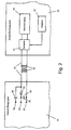
- FIG. 2 shows an embodiment in which the potential separation 48 by a DC voltage converter is formed.
- Fig. 2 shows a section of the sensor assembly 10 and a section of the evaluation module 20 with the power supply 32 and the clock 37.
- the DC converter contains a chopper 51, which DC voltage supplied by the power supply 32 receives, one connected to the output of the chopper 51 Transformer 52 and one to the secondary winding the rectifier circuit connected to the transformer 52 53 with a rectifier 54 and a filter capacitor 55.
- the chopper 51 is in the evaluation module 20 is arranged, the rectifier circuit 53 arranged in the sensor assembly 10 and the transformer 52 is for potential isolation in the supply line 33 inserted the chopper 51 with the rectifier circuit 53 connects.
- the clock input of the chopper 51 receives the clock signal supplied by the clock generator 37.
- the Chopper 51 generates from the power supply 32 supplied DC voltage a rectangular AC voltage, whose frequency is determined by the clock generator 37. This Rectangular AC voltage is applied via transformer 52 transmitted and through the rectifier circuit 53 in the DC supply voltage of the sensor assembly 10 converted to the output terminals 56 and 57 of the Rectifier circuit 53 is available.
- the operating cycle for the sensor module before rectification 10 derived, for example by means of a between the secondary winding of the transformer 52 and the Rectifier circuit 53 connected capacitor 58, from the square-wave AC voltage transmitted by the transformer 52 forms a clock signal that at the terminal 59 is available.
- the operating cycle of the sensor module 10 is thus determined by the clock generator 37.
- the unidirectional serial interface 22 an asynchronous Interface. If, on the other hand, the operating cycle of the Sensor assembly 10 in one of the ways previously described determined by the clock generator 37 of the evaluation module 20 it doesn't matter if the unidirectional serial Interface a synchronous or an asynchronous interface is.
Landscapes
- Engineering & Computer Science (AREA)
- Technology Law (AREA)
- Physics & Mathematics (AREA)
- General Physics & Mathematics (AREA)
- Arrangements For Transmission Of Measured Signals (AREA)
Claims (14)
- Dispositif de mesure comprenantcaractérisé en ce queun sous-groupe capteur qui renferme au moins un capteur destiné à capter une grandeur physique mesurée et, pour chaque capteur, un convertisseur analogique-numérique destiné à numériser le signal de mesure analogique fourni par le capteur, ainsi qu'une mémoire numérique non volatile dans laquelle sont numérisées des données caractéristiques spécifiques au capteur, etun sous-groupe d'analyse qui est relié au sous-groupe capteur par une interface numérique, et qui comprend des dispositifs pour le traitement numérique des données de mesure numérisées fournies par le sous-groupe capteur, des dispositifs de sortie pour les données de mesure traitées et des dispositifs d'alimentation électrique,l'interface numérique est une interface série unidirectionnelle qui est conçue pour la transmission de données numériques du sous-groupe capteur au sous-groupe d'analyse,la mémoire numérique non volatile contenue dans le sous groupe capteur comprend des données de configuration pour l'initialisation du sous-groupe capteur ainsi que des codes de programme et des coefficients pour le traitement des données de mesure numérisées dans le sous-groupe d'analyse etle sous-groupe capteur comprend un circuit de commande qui provoque,immédiatement après la mise sous tension du sous-groupe capteur, la lecture des données mémorisées dans la mémoire numérique non volatile, l'initialisation du sous-groupe capteur par les données de configuration lues, et la transmission du contenu de la mémoire lue au sous-groupe d'analyse, à travers l'interface série, et qui provoque,après l'exécution de la transmission du contenu de la mémoire, pendant des intervalles de temps réguliers et spontanément, la transmission à chaque fois d'un jeu de données qui contient une des données de mesure numérisées au sous-groupe d'analyse, à travers l'interface série.
- Dispositif de mesure selon la revendication 1, caractérisé en ce que le sous-groupe d'analyse comprend un circuit d'alimentation électrique et en ce que la puissance d'alimentation électrique pour le fonctionnement du sous-groupe capteur est transmise du circuit d'alimentation électrique au sous-groupe capteur par une ligne d'alimentation.
- Dispositif de mesure selon la revendication 1 ou 2, caractérisé en ce que le sous-groupe d'analyse comprend un générateur de rythme dont le signal de rythme est transmis au sous-groupe capteur par une ligne de rythme.
- Dispositif de mesure selon une des revendications précédentes, caractérisé en ce qu'une coupure de potentiel est intercalée dans chaque liaison entre le sous-groupe capteur et le sous-groupe d'analyse.
- Dispositif de mesure selon la revendication 4, caractérisé en ce que la coupure de potentiel intercalée dans une ligne de signaux est formée par un organe de transmission inductif ou capacitif.
- Dispositif de mesure selon la revendication 4, caractérisé en ce que la coupure de potentiel intercalée dans une ligne de signaux est formée par un optocoupleur.
- Dispositif de mesure selon la revendication 4, caractérisé en ce que la coupure de potentiel intercalée dans une ligne d'alimentation est constituée par un transformateur.
- Dispositif de mesure selon une des revendications 4 à 7, caractérisé en ce que les circuits du sous-groupe capteur sont connectés au potentiel du boítier.
- Dispositif de mesure selon la revendication 2, caractérisé en ce que le sous-groupe d'analyse comprend un générateur de rythme et en ce que le rythme de travail du sous-groupe capteur est dérivé, à travers la ligne d'alimentation, du signal de rythme fourni par le générateur de rythme.
- Dispositif de mesure selon la revendication 9, caractérisé en ce que l'alimentation électrique du sous-groupe capteur est assurée par l'alimentation électrique du sous-groupe d'analyse à travers un convertisseur de tension continue qui présente un hacheur disposé dans le sous-groupe d'analyse, commandé par le signal de rythme du générateur de rythme, un circuit redresseur disposé dans le sous-groupe capteur, et un transformateur intercalé dans la ligne d'alimentation, entre le hacheur et le circuit redresseur, pour la coupure de potentiel, et en ce que, dans le sous-groupe capteur, le rythme de fonctionnement est dérivé de la tension alternative fournie au circuit redresseur par le transformateur.
- Dispositif de mesure selon la revendication 1 ou 2, caractérisé en ce que le sous-groupe capteur et le sous-groupe d'analyse contiennent chacun un générateur de rythme propre pour la fourniture de leur rythme de travail et en ce que l'interface série unidirectionnelle est une interface asynchrone.
- Dispositif de mesure selon une des revendications précédentes, caractérisé en ce que le sous-groupe d'analyse renferme un dispositif de traitement des données et en ce que le traitement des données de mesure contenues dans chaque jeu de données est déclenché dans le dispositif de traitement des données par la transmission du jeu de données.
- Dispositif de mesure selon la revendication 12, caractérisé en ce que chaque jeu de données commence par un bit de départ et se termine par un bit d'arrêt.
- Dispositif de mesure selon la revendication 12 ou 13, caractérisé en ce que le dispositif de traitement des données renferme un processeur, une mémoire de programme, et une mémoire de données, et en ce que le circuit de commande contenu dans le sous-groupe capteur assure la transmission du code de mémoire contenu dans la mémoire numérique non volatile à la mémoire de programme et la transmission des données caractéristiques du capteur contenues dans la mémoire numérique non volatile à la mémoire des données.
Applications Claiming Priority (2)
| Application Number | Priority Date | Filing Date | Title |
|---|---|---|---|
| DE19730158A DE19730158A1 (de) | 1997-07-14 | 1997-07-14 | Meßanordnung |
| DE19730158 | 1997-07-14 |
Publications (2)
| Publication Number | Publication Date |
|---|---|
| EP0892249A1 EP0892249A1 (fr) | 1999-01-20 |
| EP0892249B1 true EP0892249B1 (fr) | 2002-08-14 |
Family
ID=7835676
Family Applications (1)
| Application Number | Title | Priority Date | Filing Date |
|---|---|---|---|
| EP98110899A Expired - Lifetime EP0892249B1 (fr) | 1997-07-14 | 1998-06-15 | Dispositif de mesure |
Country Status (4)
| Country | Link |
|---|---|
| US (1) | US6427129B1 (fr) |
| EP (1) | EP0892249B1 (fr) |
| JP (1) | JP2911888B2 (fr) |
| DE (2) | DE19730158A1 (fr) |
Cited By (2)
| Publication number | Priority date | Publication date | Assignee | Title |
|---|---|---|---|---|
| US8718981B2 (en) | 2011-05-09 | 2014-05-06 | Honeywell International Inc. | Modular sensor assembly including removable sensing module |
| CN104885402A (zh) * | 2012-12-13 | 2015-09-02 | 恩德莱斯和豪瑟尔两合公司 | 用于同步时钟频率的设备 |
Families Citing this family (30)
| Publication number | Priority date | Publication date | Assignee | Title |
|---|---|---|---|---|
| DE29903260U1 (de) * | 1999-02-23 | 2000-04-13 | Siemens Ag | Meßumformer |
| DE19933135A1 (de) * | 1999-07-19 | 2001-01-25 | Thomson Brandt Gmbh | Galvanische Isoliervorrichtung mit Optokoppler für bidirektionale Verbindungsleitungen |
| DE19947501C5 (de) * | 1999-10-01 | 2016-06-30 | Ifm Electronic Gmbh | Aktuator-Sensor-Interface-Slave |
| DE10114504A1 (de) | 2001-03-23 | 2002-10-02 | Bosch Gmbh Robert | Verfahren zur Übertragung von Daten von wenigstens einem Sensor zu einem Steuergerät |
| US7180798B2 (en) * | 2001-04-12 | 2007-02-20 | Fuji Electric Co., Ltd. | Semiconductor physical quantity sensing device |
| DE10217447B4 (de) * | 2002-04-18 | 2004-08-19 | Knick Elektronische Meßgeräte GmbH & Co. | Hilfsenergie-gestützter Signaltrenner für Messsignale |
| DE10238529A1 (de) | 2002-08-22 | 2004-03-04 | Robert Bosch Gmbh | Steuergerät |
| US6677740B1 (en) * | 2002-09-24 | 2004-01-13 | Tonic Fitness Technology, Inc. | Applied control system of the power periphery of a health apparatus having function of power generation |
| DE10258965B4 (de) * | 2002-12-16 | 2007-06-21 | Endress + Hauser Gmbh + Co. Kg | Vorrichtung zur Optimierung der Leistungsbilanz eines Sensors für die Bestimmung und/oder Überwachung einer physikalischen Prozessgröße eines Mediums |
| FR2867566B1 (fr) * | 2004-03-10 | 2006-06-02 | Chauvin Arnoux | Agencement d'un instrument de mesure avec une famille de capteurs |
| EP1730472A1 (fr) * | 2004-04-02 | 2006-12-13 | Kistler Holding AG | Detecteur comportant un composant a ondes de surface |
| WO2005102202A1 (fr) * | 2004-04-26 | 2005-11-03 | Orthosoft Inc. | Procede d'etalonnage permanent reposant sur des mesures effectives |
| DE102005021000B4 (de) * | 2005-05-03 | 2014-09-04 | Krohne Meßtechnik GmbH & Co KG | Meßgerät |
| US20060290488A1 (en) * | 2005-05-27 | 2006-12-28 | Bionime Corporation | Coding module and sensing meter and system therefor |
| US8290747B2 (en) * | 2005-10-21 | 2012-10-16 | Microstrain, Inc. | Structural damage detection and analysis system |
| DE102006020342A1 (de) * | 2006-04-28 | 2007-10-31 | Endress + Hauser Gmbh + Co. Kg | Vorrichtung zur Bestimmung und/oder Überwachung einer Prozessgrösse |
| US8010322B2 (en) | 2006-05-17 | 2011-08-30 | Honeywell International Inc. | Signal conditioning IC with conditioning-coefficient memory |
| US8175835B2 (en) * | 2006-05-17 | 2012-05-08 | Honeywell International Inc. | Flow sensor with conditioning-coefficient memory |
| DE502006008081D1 (de) * | 2006-06-30 | 2010-11-25 | Sick Ag | Anschlussmodul für Sensoren |
| DE102006053866A1 (de) * | 2006-11-14 | 2008-05-15 | Endress + Hauser Process Solutions Ag | Verfahren zum Betreiben eines nach dem Blockmodell arbeitenden modularen Feldgerätes der Automatisierungstechnik |
| US7933731B2 (en) * | 2008-02-29 | 2011-04-26 | Omega Engineering, Inc. | Smart sensor |
| DE102009002009A1 (de) * | 2009-03-31 | 2010-10-07 | Endress + Hauser Gmbh + Co. Kg | Vorrichtung zur Reduzierung bzw. Minimierung von Störsignalen bei einem Feldgerät der Prozessautomatisierung |
| DE202009018890U1 (de) * | 2009-07-28 | 2014-04-07 | Ahlborn Mess- Und Regelungstechnik Gmbh | Elektronisches Modul, insbesondere digitaler Messfühler |
| US8742968B2 (en) * | 2011-11-11 | 2014-06-03 | Microchip Technology Incorporated | Analog front end device with two-wire interface |
| DE102015111594A1 (de) | 2015-07-16 | 2017-01-19 | Endress+Hauser Conducta Gmbh+Co. Kg | Verfahren zur Kommunikation zwischen einem Sensor und einem mit dem Sensor verbindbaren Anschlusselement |
| JP6571442B2 (ja) * | 2015-08-07 | 2019-09-04 | Necプラットフォームズ株式会社 | 交流入力直流出力型電源およびその制御方法 |
| ES2561178B2 (es) * | 2015-09-11 | 2016-07-12 | Metro De Madrid, S.A. | Método y sistema para la adquisición de datos digitales con reducción de potencia |
| DE102016124488A1 (de) * | 2016-12-15 | 2018-06-21 | Endress+Hauser SE+Co. KG | Feldgerät der Prozessmesstechnik |
| DE102019003206B3 (de) * | 2019-05-07 | 2020-08-20 | Festo Se & Co. Kg | Sicherheitsanordnung |
| DE102021102522A1 (de) * | 2021-02-03 | 2022-08-04 | Bürkert Werke GmbH & Co. KG | System zur Datenübertragung sowie Ventilsystem |
Family Cites Families (16)
| Publication number | Priority date | Publication date | Assignee | Title |
|---|---|---|---|---|
| US4303984A (en) * | 1979-12-14 | 1981-12-01 | Honeywell Inc. | Sensor output correction circuit |
| CH645719A5 (de) * | 1980-10-28 | 1984-10-15 | Hans Guegler | Verfahren und einrichtung zur erfassung, aufzeichnung und auswertung von physikalischen messdaten. |
| GB2119095B (en) * | 1982-03-31 | 1985-12-24 | Goldcrest Electronics Limited | Data processing systems for motor vehicles |
| US4593365A (en) * | 1983-04-06 | 1986-06-03 | Halliburton Company | Apparatus and method for monitoring a plurality of flow meters |
| DE3446248A1 (de) * | 1984-12-19 | 1986-06-19 | Robert Bosch Gmbh, 7000 Stuttgart | Sensor zur messung physikalischer groessen und verfahren zum abgleich des sensors |
| DE3522815A1 (de) * | 1985-06-26 | 1987-01-08 | Mak Maschinenbau Krupp | Mess- und registriervorrichtung |
| US4818994A (en) * | 1987-10-22 | 1989-04-04 | Rosemount Inc. | Transmitter with internal serial bus |
| DE3743846A1 (de) | 1987-12-23 | 1989-07-13 | Porsche Ag | Messwertaufnehmer |
| US5089979A (en) * | 1989-02-08 | 1992-02-18 | Basic Measuring Instruments | Apparatus for digital calibration of detachable transducers |
| DE59010841D1 (de) * | 1990-05-29 | 1998-09-03 | Siemens Ag | Messgerät zum Ermitteln, Verarbeiten und Anzeigen von Daten über Durchflussmengen von Flüssigkeiten, Gasen oder elektrischen Strömen |
| DE9006273U1 (fr) * | 1990-06-02 | 1991-10-10 | Rau Gmbh, 8900 Augsburg, De | |
| GB9208190D0 (en) * | 1992-04-11 | 1992-05-27 | Elcometer Instr Ltd | Measuring instrument |
| US5347476A (en) * | 1992-11-25 | 1994-09-13 | Mcbean Sr Ronald V | Instrumentation system with multiple sensor modules |
| US5706215A (en) * | 1995-06-30 | 1998-01-06 | Harris Corporation | Method and system for adjusting replacement component characteristics |
| US6032109A (en) * | 1996-10-21 | 2000-02-29 | Telemonitor, Inc. | Smart sensor module |
| US6023969A (en) * | 1997-09-17 | 2000-02-15 | Feller; Murray F. | Flow modulated mass flow sensor |
-
1997
- 1997-07-14 DE DE19730158A patent/DE19730158A1/de not_active Withdrawn
-
1998
- 1998-06-15 EP EP98110899A patent/EP0892249B1/fr not_active Expired - Lifetime
- 1998-06-15 DE DE59805163T patent/DE59805163D1/de not_active Expired - Lifetime
- 1998-07-08 US US09/111,967 patent/US6427129B1/en not_active Expired - Lifetime
- 1998-07-13 JP JP10197509A patent/JP2911888B2/ja not_active Expired - Fee Related
Cited By (3)
| Publication number | Priority date | Publication date | Assignee | Title |
|---|---|---|---|---|
| US8718981B2 (en) | 2011-05-09 | 2014-05-06 | Honeywell International Inc. | Modular sensor assembly including removable sensing module |
| CN104885402A (zh) * | 2012-12-13 | 2015-09-02 | 恩德莱斯和豪瑟尔两合公司 | 用于同步时钟频率的设备 |
| CN104885402B (zh) * | 2012-12-13 | 2018-09-21 | 恩德莱斯和豪瑟尔欧洲两合公司 | 用于同步时钟频率的设备 |
Also Published As
| Publication number | Publication date |
|---|---|
| EP0892249A1 (fr) | 1999-01-20 |
| DE59805163D1 (de) | 2002-09-19 |
| US6427129B1 (en) | 2002-07-30 |
| JPH1186176A (ja) | 1999-03-30 |
| DE19730158A1 (de) | 1999-02-18 |
| JP2911888B2 (ja) | 1999-06-23 |
Similar Documents
| Publication | Publication Date | Title |
|---|---|---|
| EP0892249B1 (fr) | Dispositif de mesure | |
| EP0883097B1 (fr) | Dispositif pour la transmission de signaux entre un émetteur et un récepteur | |
| EP1192614B1 (fr) | Transducteur de mesure a signal de sortie corrige | |
| EP0324067B1 (fr) | Capteur | |
| DE19846461B4 (de) | Sensoreinstellschaltung | |
| EP1733410A1 (fr) | Systeme comprenant un fusible de securite pour vehicule et un convertisseur analogique/numerique | |
| EP0744724A1 (fr) | Dispositif d'alimentation d'énergie par fil d'un émetteur de signal par le récepteur du signal | |
| DE4141065A1 (de) | Verfahren zur temperaturkompensation von induktiven sensoren | |
| DE2308887C3 (de) | Temperaturmeßverfahren und -einrichtung mit Speicherung der Meßwerte in einem temperaturisolierten Gefäß | |
| DE102008043336A1 (de) | Modulares Messgerät mit verteilten Daten und Algorithmen | |
| DE102006062184A1 (de) | Steckverbinderkupplung für ein Sensormodul und Sensormodul mit einer solchen Steckverbinderkupplung | |
| DE10130215B4 (de) | Meßgrößenaufnehmer mit angeschlossenem Datenspeicher | |
| EP0906595B1 (fr) | Circuit permettant a des appareils exterieurs de communiquer au moyen d'un bus avec un systeme centralise/decentralise de traitement de donnees | |
| DE60202557T2 (de) | Kalibrierung von isolierten Analog-Digital-Wandlern | |
| DE3832985A1 (de) | Einrichtung zum verarbeiten und drahtlosen senden von messwerten | |
| DE4016922C2 (fr) | ||
| EP0772320A2 (fr) | Dispositif pour la transmission de signaux par bus de secteur | |
| DE4006603A1 (de) | Feldsensor-kommunikationsmethode und system | |
| EP3380852B1 (fr) | Transformateur de mesure de courant inductif | |
| DE3433760A1 (de) | Mikroelektronisches messdaten-erfassungssystem | |
| EP0986801B1 (fr) | Appareil de controle et/ou de surveillance | |
| DE102008030908B4 (de) | Datenspeicherschaltung mit integrierter Datenspeichereinheit für einen Sensor mit physikalisch-elektrischem Wandler | |
| DE2935831C2 (fr) | ||
| DE4426765C1 (de) | Schaltungsanordnung zur Anpassung eines Zweileiter-Meßumformers an ein Vierleiter-Meßsystem | |
| AT397433B (de) | Einrichtung zur elektrischen messung einer nichtelektrischen messgrösse |
Legal Events
| Date | Code | Title | Description |
|---|---|---|---|
| PUAI | Public reference made under article 153(3) epc to a published international application that has entered the european phase |
Free format text: ORIGINAL CODE: 0009012 |
|
| AK | Designated contracting states |
Kind code of ref document: A1 Designated state(s): DE FR GB IT |
|
| AX | Request for extension of the european patent |
Free format text: AL;LT;LV;MK;RO;SI |
|
| 17P | Request for examination filed |
Effective date: 19990618 |
|
| AKX | Designation fees paid |
Free format text: DE FR GB IT |
|
| 17Q | First examination report despatched |
Effective date: 20010220 |
|
| GRAG | Despatch of communication of intention to grant |
Free format text: ORIGINAL CODE: EPIDOS AGRA |
|
| GRAH | Despatch of communication of intention to grant a patent |
Free format text: ORIGINAL CODE: EPIDOS IGRA |
|
| GRAH | Despatch of communication of intention to grant a patent |
Free format text: ORIGINAL CODE: EPIDOS IGRA |
|
| RAP1 | Party data changed (applicant data changed or rights of an application transferred) |
Owner name: ENDRESS + HAUSER GMBH + CO.KG. |
|
| GRAA | (expected) grant |
Free format text: ORIGINAL CODE: 0009210 |
|
| AK | Designated contracting states |
Kind code of ref document: B1 Designated state(s): DE FR GB IT |
|
| PG25 | Lapsed in a contracting state [announced via postgrant information from national office to epo] |
Ref country code: IT Free format text: LAPSE BECAUSE OF FAILURE TO SUBMIT A TRANSLATION OF THE DESCRIPTION OR TO PAY THE FEE WITHIN THE PRESCRIBED TIME-LIMIT;WARNING: LAPSES OF ITALIAN PATENTS WITH EFFECTIVE DATE BEFORE 2007 MAY HAVE OCCURRED AT ANY TIME BEFORE 2007. THE CORRECT EFFECTIVE DATE MAY BE DIFFERENT FROM THE ONE RECORDED. Effective date: 20020814 |
|
| REG | Reference to a national code |
Ref country code: GB Ref legal event code: FG4D Free format text: NOT ENGLISH |
|
| REF | Corresponds to: |
Ref document number: 59805163 Country of ref document: DE Date of ref document: 20020919 |
|
| GBT | Gb: translation of ep patent filed (gb section 77(6)(a)/1977) |
Effective date: 20021129 |
|
| ET | Fr: translation filed | ||
| PLBE | No opposition filed within time limit |
Free format text: ORIGINAL CODE: 0009261 |
|
| STAA | Information on the status of an ep patent application or granted ep patent |
Free format text: STATUS: NO OPPOSITION FILED WITHIN TIME LIMIT |
|
| 26N | No opposition filed |
Effective date: 20030515 |
|
| PGFP | Annual fee paid to national office [announced via postgrant information from national office to epo] |
Ref country code: GB Payment date: 20140618 Year of fee payment: 17 |
|
| GBPC | Gb: european patent ceased through non-payment of renewal fee |
Effective date: 20150615 |
|
| PG25 | Lapsed in a contracting state [announced via postgrant information from national office to epo] |
Ref country code: GB Free format text: LAPSE BECAUSE OF NON-PAYMENT OF DUE FEES Effective date: 20150615 |
|
| REG | Reference to a national code |
Ref country code: FR Ref legal event code: PLFP Year of fee payment: 19 |
|
| REG | Reference to a national code |
Ref country code: FR Ref legal event code: PLFP Year of fee payment: 20 |
|
| PGFP | Annual fee paid to national office [announced via postgrant information from national office to epo] |
Ref country code: DE Payment date: 20170621 Year of fee payment: 20 Ref country code: FR Payment date: 20170621 Year of fee payment: 20 |
|
| REG | Reference to a national code |
Ref country code: DE Ref legal event code: R081 Ref document number: 59805163 Country of ref document: DE Owner name: ENDRESS+HAUSER SE+CO. KG, DE Free format text: FORMER OWNER: ENDRESS + HAUSER GMBH + CO. KG, 79689 MAULBURG, DE |
|
| REG | Reference to a national code |
Ref country code: DE Ref legal event code: R071 Ref document number: 59805163 Country of ref document: DE |