EP0892152A1 - Heating or cooling device for a carter with circular section - Google Patents
Heating or cooling device for a carter with circular section Download PDFInfo
- Publication number
- EP0892152A1 EP0892152A1 EP98401800A EP98401800A EP0892152A1 EP 0892152 A1 EP0892152 A1 EP 0892152A1 EP 98401800 A EP98401800 A EP 98401800A EP 98401800 A EP98401800 A EP 98401800A EP 0892152 A1 EP0892152 A1 EP 0892152A1
- Authority
- EP
- European Patent Office
- Prior art keywords
- tubes
- distributors
- gas
- networks
- housing
- Prior art date
- Legal status (The legal status is an assumption and is not a legal conclusion. Google has not performed a legal analysis and makes no representation as to the accuracy of the status listed.)
- Granted
Links
Images


Classifications
-
- F—MECHANICAL ENGINEERING; LIGHTING; HEATING; WEAPONS; BLASTING
- F01—MACHINES OR ENGINES IN GENERAL; ENGINE PLANTS IN GENERAL; STEAM ENGINES
- F01D—NON-POSITIVE DISPLACEMENT MACHINES OR ENGINES, e.g. STEAM TURBINES
- F01D25/00—Component parts, details, or accessories, not provided for in, or of interest apart from, other groups
- F01D25/08—Cooling; Heating; Heat-insulation
-
- F—MECHANICAL ENGINEERING; LIGHTING; HEATING; WEAPONS; BLASTING
- F01—MACHINES OR ENGINES IN GENERAL; ENGINE PLANTS IN GENERAL; STEAM ENGINES
- F01D—NON-POSITIVE DISPLACEMENT MACHINES OR ENGINES, e.g. STEAM TURBINES
- F01D11/00—Preventing or minimising internal leakage of working-fluid, e.g. between stages
- F01D11/08—Preventing or minimising internal leakage of working-fluid, e.g. between stages for sealing space between rotor blade tips and stator
- F01D11/14—Adjusting or regulating tip-clearance, i.e. distance between rotor-blade tips and stator casing
- F01D11/20—Actively adjusting tip-clearance
- F01D11/24—Actively adjusting tip-clearance by selectively cooling-heating stator or rotor components
-
- F—MECHANICAL ENGINEERING; LIGHTING; HEATING; WEAPONS; BLASTING
- F05—INDEXING SCHEMES RELATING TO ENGINES OR PUMPS IN VARIOUS SUBCLASSES OF CLASSES F01-F04
- F05D—INDEXING SCHEME FOR ASPECTS RELATING TO NON-POSITIVE-DISPLACEMENT MACHINES OR ENGINES, GAS-TURBINES OR JET-PROPULSION PLANTS
- F05D2250/00—Geometry
- F05D2250/10—Two-dimensional
- F05D2250/14—Two-dimensional elliptical
- F05D2250/141—Two-dimensional elliptical circular
Definitions
- the invention relates to a device for cooling or heating of a housing circular.
- a device already used consists of have two networks of semicircular tubes around of the casing, each of the networks therefore extending over a half circumference of the housing and being powered by a conduit, which is connected to a distributor box connected to each of the pipes in the network, in the middle of their length.
- the gas therefore disperses in the tubes of the network by traversing them towards their ends at from the middle, and leaves them by borrowing orifices directed towards the housing.
- This construction explains that these tubes are called "necklaces of shower”.
- the known device Like the known device, it includes a gas distribution network in distributors connecting to networks of tubes surrounding the casing on respective parts of the circumferences; at place where a distributor is connected in the middle of tube networks, two distributors are arranged at ends of the networks, each of these two distributors connecting to a respective group of tubes of the considered network: the gas flows through the two groups of tubes in opposite directions, which balances heat gain around the circumference, each generator of the casing being subjected to a double gas blowing, the first of which originates from one of network tube groups, is hotter as the other, from the other group, is fresher.
- conduits opening into a pair of distributors are connected to a link occupying half of their section and extending to at least one of the sockets in passing through a stop surface of said socket.
- This last duct slightly penetrates into the duct more wide of the distribution network, therefore recovers the half of the bit rate that comes out and transmits this half of flow to the distributor located beyond the socket liaison; the other half of the gas flow comes out of the distribution duct around the connecting duct and enters the other dispenser.
- the connecting pipe having a section half less than that of the duct distribution, to which it is connected with play, completes the system, the aim of which is to equalize heating or cooling.
- a possible improvement consists in provide the device with a flow control valve heating or cooling gas, which is controlled by a calculator or function of the regimes reached by the machine.
- a flow control valve heating or cooling gas which is controlled by a calculator or function of the regimes reached by the machine.
- it is particularly advantageous to reduce the gas flow blown during start-up: if a large flow is delivered from this moment, while the machine is still cold, the housing heats up much more slowly as the rotor and its blades, whose ends expand to the point of rubbing against the inner wall of the housing.
- This wall is normally filled with a layer of soft material, called abradable, which erodes under the effect of friction and prevents damage to the rotor blades, but play reappearing between them and the abradable layer now eroded is increased when the housing is heated and expanded in turn. It is therefore a question of avoiding this result.
- abradable a layer of soft material
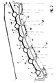
- the device illustrated as a whole at Figure 1, has substantially the shape of a crown that we have to imagine placed around a housing cylindrical or conical shown elsewhere.
- This crown is essentially composed of three networks of tubes 1, identical and each extending over a third of the circumference of the housing thus forming an almost entirely continuous surface.
- Each of the tube networks 1 includes six parallel tubes 2 and as an extension from one network to another and is completed by two distributor boxes 3 to which branch their tubes 2, which gives three pairs distributor boxes 3 adjacent to the limits of the three tube networks 1.
- the housings distributors 3 and the tubes 2 are supplied with gas heating or cooling by a network of conduits first comprising a single conduit 4 which is splits into a first conduit 5 which goes towards a first pair of distributor boxes 3, at the top in the figure, and in a second conduit 6 which itself splits into two conduits, one of which extends over 7 the lower right of the figure and supplies a second pair of enclosures dispensers 3 at this location, while the other is not visible in the figure but extends behind one of the tube networks 1 to connect to the third pair of distributor boxes 3, also invisible but located behind the lower left of the figure.
- the ducts are chosen so that the three pairs of distributor boxes 3 are supplied by equal gas flows at the same temperature: the lengths of conduit to travel to achieve each pair of housings are all equal, the single duct 4 dividing at the junction of two networks of tubes 1, and conduit 6 in the middle of one of these two networks of tubes 1; the conduit 5 extends over about a third of the circumference of the housing, and the duct 6 on a sixth in circumference, as well as the two conduits in which it splits.
- Figure 2 shows that the tube networks 1 are composed of two corrugated sheets 8 turned over and joined so that their corrugations 9 are opposite and come face to face to form the tubes 2.
- the corrugated sheets 8 have flat portions 10 adjoining corrugations 9, in contact when the 8 sheets are assembled and riveted or united by a other way.
- the tubes 2 are provided with orifices 11 directed to casing 12 to project gas there heating or cooling. This gas builds up in an annular chamber 13 delimited by the casing 12 and tube networks 1 but can escape from it by additional orifices 14 formed through adjoining portions 10.
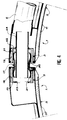
- Figure 3 shows that the gas distribution each lead into one of the distributor boxes 3 adjacent pairs mentioned above and their content is spreading first in this distributor box 3 before a half goes into the other distributor box 3 in passing through a cuff 17 which joins them.
- the six tubes 2 of tube networks 1 are alternately connected to one of the opposite 3 distributor boxes and located at the ends of these networks, so that the gas flows through three of tubes 2 in one direction and in the other three tubes 2 in the direction opposite: the gas heats up in tubes 2 as in the anterior device and therefore exits through the orifices 11 at increasing temperatures away from distributor boxes, but if we consider a generator of the casing 12, it receives gas from three tubes 2 having traveled a relatively long way and gas from three tubes 2 having traveled a path relatively short, i.e. both gas strongly heated and weakly heated gas and therefore a practically uniform quantity of heat: the object of the invention is thus achieved.
- the housings distributors 3 have protrusions 18 to the exterior and in extension, and that the conduits feed such as 5 and 7 end up in the alignment of these protrusions 18 and penetrate into one of them.
- the protrusions 18 each contain a socket 19 which partially delimits them, the sockets 19 being facing facing and connected by one of the cuffs 17; the cuff 17 is terminated by two spherical portions 20, open at their opposite ends 21 and which are able to roll and slide on the internal surface of sockets 19.
- Tube networks 1 and sockets 19 can therefore move mutually without producing more than a rotation or a sliding movement of the cuff 17 in sockets 19, and without sealing and even less the connection between distributor boxes 3 is broken.
- the cuff 17 must obviously be inserted sufficiently into the sockets 19 so that its extraction is impossible even if the networks of tubes 1 deviate; through elsewhere, the sockets 19 are provided with surfaces stop 22 which surround the cuff 17 and him prohibit moving indefinitely in the same direction, because it would come up against them.
- the surfaces stop 22 include a central opening 23 for allow the entry of gas into the boxes distributors 3.
- a connecting tube 24 is welded to one of these openings 23, and the other of the openings is free.
- the connecting tube 24 is connected to the conduit power supply such as 5 occupying only the half of its section, which guarantees the passage of the half of the gas flow in the distributor box 3 opposite, on the left in the figure, by the connecting tube 24, while the other half of the flow stops against the sleeve 19 and is forced back into the tubes 2 of the distributor 3 on the right.
- gas flow can be controlled by a progressive opening valve 25, controlled by a computer 26 depending on the speed reached, for adjust the gas flow rate supplied to the device and therefore the expansion undergone by the casing 12.
- the computer 26 can be informed by speed sensors, temperature, pressure, etc. who measure quantities present in the machine, and it uses these measurements using empirically established tables or formulas.
- We finally figured point 27 of sampling gas through the supply line 4 it's about usually from a point in the gas flow stream of the machine, from which part of the flow is withdrawn, in a manner widely known in the art.
- the invention will especially find utility on turbomachine turbines, where the hotter gases that elsewhere make it more necessary.
Landscapes
- Engineering & Computer Science (AREA)
- Mechanical Engineering (AREA)
- General Engineering & Computer Science (AREA)
- Heat-Exchange Devices With Radiators And Conduit Assemblies (AREA)
- Pipeline Systems (AREA)
- Quick-Acting Or Multi-Walled Pipe Joints (AREA)
- Lubrication Details And Ventilation Of Internal Combustion Engines (AREA)
Abstract
Description
L'invention a trait à un dispositif de refroidissement ou d'échauffement d'un carter circulaire.The invention relates to a device for cooling or heating of a housing circular.
Le souhait d'accroítre les rendements des moteurs est aujourd'hui général. Dans l'aéronautique, un moyen d'y parvenir consiste à réduire autant que possible les jeux entre le rotor et le stator, notamment à l'endroit des extrémités libres des aubes tournantes du rotor et des portées du carter qui leur font face. On a déjà conçu des moyens pour y parvenir, notamment en faisant varier le diamètre du carter. Le procédé le plus usuel consiste à lui imposer des dilatations ou des contractions d'origine thermique en soufflant sur sa surface extérieure, opposée à la veine d'écoulement des gaz, du gaz prélevé d'autres parties de la machine et se trouvant à la température souhaitée pour échauffer ou refroidir le carter selon le cas.The desire to increase yields engines is general today. In aeronautics, one way to do this is to reduce as much as possible clearances between the rotor and the stator, especially at the free ends of the blades rotors of the rotor and the bearing surfaces of the casing which face each other. We have already devised means to achieve this, in particular by varying the diameter of the casing. The the most common method is to impose thermal expansion or contraction in blowing on its outer surface, opposite the vein gas flow, gas taken from other parts machine and at the desired temperature to heat or cool the housing as appropriate.
Il est cependant fondamental d'obtenir une grande uniformité de température sur toute la surface du carter. Un dispositif déjà employé consiste à disposer deux réseaux de tubes semi-circulaires autour du carter, chacun des réseaux s'étendant donc sur une demi-circonférence du carter et étant alimenté par un conduit, qui est branché à un boítier distributeur raccordé à chacun des tubes du réseau, au milieu de leur longueur. Le gaz se disperse donc dans les tubes du réseau en les parcourant vers leurs extrémités à partir du milieu, et les quitte en empruntant des orifices dirigés vers le carter. Cette construction explique que ces tubes sont appelés "colliers de douche".It is however fundamental to obtain a high temperature uniformity over the entire surface of the housing. A device already used consists of have two networks of semicircular tubes around of the casing, each of the networks therefore extending over a half circumference of the housing and being powered by a conduit, which is connected to a distributor box connected to each of the pipes in the network, in the middle of their length. The gas therefore disperses in the tubes of the network by traversing them towards their ends at from the middle, and leaves them by borrowing orifices directed towards the housing. This construction explains that these tubes are called "necklaces of shower".
Si un tel dispositif assure en vérité un soufflage de gaz à peu près uniformément réparti sur toute la surface extérieure du carter, il échoue pourtant à lui imposer un diamètre uniforme car on constate que le gaz s'échauffe pendant le parcours dans les tubes et peut donc céder plus de chaleur en arrivant aux extrémités des tubes que près des boítiers distributeurs ; le carter, de plus en plus échauffé en s'éloignant des génératrices situées devant les boítiers distributeurs, prend donc une forme ovoïde dont le plus grand diamètre est situé aux génératrices de raccordement des réseaux de tubes. Le dispositif sujet de l'invention a pour fonction d'assurer un échauffement, ou au contraire un refroidissement, beaucoup plus uniforme d'un carter à section circulaire. Il comprend comme le dispositif connu un réseau de distribution de gaz dans des distributeurs se branchant à des réseaux de tubes entourant le carter sur des parties respectives des circonférences ; au lieu qu'un distributeur soit branché au milieu des réseaux de tubes, deux distributeurs sont disposés aux extrémités des réseaux, chacun de ces deux distributeurs se branchant à un groupe respectif des tubes du réseau considéré : le gaz parcourt les deux groupes de tubes dans des sens opposés, ce qui équilibre les apports de chaleur sur la circonférence, chaque génératrice du carter étant soumise à un double soufflage de gaz, dont le premier, originaire d'un des groupes de tubes du réseau, est d'autant plus chaud que l'autre, originaire de l'autre groupe, est plus frais. If such a device actually ensures a gas blowing almost uniformly distributed over the entire outer surface of the housing, it fails yet to impose a uniform diameter on it because we finds that the gas heats up during the journey in tubes and can therefore give off more heat in arriving at the ends of the tubes only near the housings distributors; the casing, more and more heated in moving away from the generators located in front of the dispenser boxes, therefore takes an ovoid shape whose largest diameter is located at the generators for connecting tube networks. The device subject of the invention has the function of ensuring a heating, or on the contrary cooling, much more uniform of a section housing circular. Like the known device, it includes a gas distribution network in distributors connecting to networks of tubes surrounding the casing on respective parts of the circumferences; at place where a distributor is connected in the middle of tube networks, two distributors are arranged at ends of the networks, each of these two distributors connecting to a respective group of tubes of the considered network: the gas flows through the two groups of tubes in opposite directions, which balances heat gain around the circumference, each generator of the casing being subjected to a double gas blowing, the first of which originates from one of network tube groups, is hotter as the other, from the other group, is fresher.
On trouve donc deux fois plus de distributeurs que de réseaux de tubes, chaque paire de réseaux consécutifs de tubes possédant deux distributeurs adjacents. Il est avantageux, dans de telles circonstances, de faire déboucher un unique conduit de distribution de gaz dans les deux distributeurs de ces paires à la fois, à condition d'assurer une liaison convenable de ces distributeurs, qui peuvent être soumis à des déplacements de nature imprévisible à cause des déformations d'origine thermique. On propose de les relier par une manchette comprenant deux extrémités en portion de sphère ouverte et en appui coulissant dans des douilles délimitant les distributeurs et pourvues de butées d'arrêt de la manchette.So we find twice as many distributors than tube networks, each pair of consecutive arrays of tubes with two adjacent distributors. It is advantageous, in such circumstances, to lead to a single gas distribution pipe in both distributors of these pairs at a time, provided to ensure an adequate connection of these distributors, which may be subject to displacement of nature unpredictable due to original deformations thermal. We suggest connecting them with a cuff comprising two ends in portion of open sphere and by sliding support in sockets delimiting the distributors and provided with stops for the cuff.
Enfin, les conduits débouchant dans une paire de distributeurs sont abouchés à un conduit de liaison occupant une moitié de leur section et s'étendant jusqu'à au moins une des douilles en traversant une surface d'arrêt de ladite douille. Ce dernier conduit pénètre légèrement dans le conduit plus large du réseau de distribution, récupère donc la moitié du débit qui en sort et transmet cette moitié de débit au distributeur situé au-delà de la douille de liaison ; l'autre moitié du débit de gaz sort du conduit de distribution autour du conduit de liaison et entre dans l'autre distributeur. Le conduit de liaison ayant une section moitié moindre que celle du conduit de distribution, auquel il est raccordé avec du jeu, complète donc le dispositif dont le but est d'égaliser l'échauffement ou le refroidissement.Finally, the conduits opening into a pair of distributors are connected to a link occupying half of their section and extending to at least one of the sockets in passing through a stop surface of said socket. This last duct slightly penetrates into the duct more wide of the distribution network, therefore recovers the half of the bit rate that comes out and transmits this half of flow to the distributor located beyond the socket liaison; the other half of the gas flow comes out of the distribution duct around the connecting duct and enters the other dispenser. The connecting pipe having a section half less than that of the duct distribution, to which it is connected with play, completes the system, the aim of which is to equalize heating or cooling.
Un perfectionnement possible consiste à pourvoir le dispositif d'une vanne de commande du débit de gaz de chauffage ou de refroidissement, qui est pilotée par un calculateur ou fonction des régimes atteints par la machine. Dans le cas principalement envisagé d'un soufflage de gaz frais sur le carter, il est notamment avantageux de réduire le débit de gaz soufflé pendant le démarrage : si un débit important est délivré dès ce moment, alors que la machine est encore froide, le carter s'échauffe beaucoup plus lentement que le rotor et ses aubes, dont les extrémités se dilatent au point de venir frotter contre la paroi interne du carter. Cette paroi est normalement garnie d'une couche de matière tendre, appelée abradable, qui s'érode sous l'effet du frottement et évite l'endommagement des aubes du rotor, mais le jeu qui réapparaít entre celles-ci et la couche abradable désormais érodée est augmenté quand le carter s'est échauffé et dilaté à son tour. Il s'agit donc d'éviter ce résultat.A possible improvement consists in provide the device with a flow control valve heating or cooling gas, which is controlled by a calculator or function of the regimes reached by the machine. In the case mainly envisaged a blowing of fresh gas on the crankcase, it it is particularly advantageous to reduce the gas flow blown during start-up: if a large flow is delivered from this moment, while the machine is still cold, the housing heats up much more slowly as the rotor and its blades, whose ends expand to the point of rubbing against the inner wall of the housing. This wall is normally filled with a layer of soft material, called abradable, which erodes under the effect of friction and prevents damage to the rotor blades, but play reappearing between them and the abradable layer now eroded is increased when the housing is heated and expanded in turn. It is therefore a question of avoiding this result.
On va maintenant décrire l'invention plus en détail à l'aide des figures suivantes, qui sont annexées à titre illustratif et non limitatif :
- la figure 1 est une vue générale du dispositif,
- la figure 2 est une coupe des réseaux de tubes illustrant leur mode de fabrication et leur emplacement,
- la figure 3 est une représentation à plat du dispositif, explicative de son fonctionnement,
- et la figure 4 illustre le mode de liaison des boítiers distributeurs.
- FIG. 1 is a general view of the device,
- FIG. 2 is a section of the tube networks illustrating their method of manufacture and their location,
- FIG. 3 is a flat representation of the device, explaining its operation,
- and Figure 4 illustrates the connection mode of the distributor boxes.
Le dispositif, illustré dans son ensemble à
la figure 1, a sensiblement la forme d'une couronne
qu'on doit imaginer placée autour d'un carter
cylindrique ou conique représenté ailleurs. Cette
couronne est composée essentiellement de trois réseaux
de tubes 1, identiques et s'étendant chacun sur un
tiers de la circonférence du carter en formant ainsi
une surface presque entièrement continue. Chacun des
réseaux de tubes 1 comprend six tubes 2 parallèles et
en prolongement d'un réseau à l'autre et est terminé
par deux boítiers distributeurs 3 auxquels
s'embranchent leurs tubes 2, ce qui donne trois paires
de boítiers distributeurs 3 adjacents situés aux
limites des trois réseaux de tubes 1. Les boítiers
distributeurs 3 et les tubes 2 sont alimentés en gaz
d'échauffement ou de refroidissement par un réseau de
conduits comprenant d'abord un conduit unique 4 qui se
dédouble en un premier conduit 5 qui se dirige vers une
première paire de boítiers distributeurs 3, au sommet
sur la figure, et en un second conduit 6 qui lui-même
se dédouble en deux conduits, dont l'un 7 s'étend sur
la partie inférieure de droite de la figure et
approvisionne une deuxième paire de boítiers
distributeurs 3 à cet endroit, alors que l'autre n'est
pas visible sur la figure mais s'étend derrière un des
réseaux de tubes 1 pour se raccorder à la troisième
paire de boítiers distributeurs 3, invisible elle aussi
mais située derrière la partie inférieure gauche de la
figure. Les conduits sont choisis pour que les trois
paires de boítiers distributeurs 3 soient alimentées
par des débits égaux de gaz à une même température :
les longueurs de conduit à parcourir pour parvenir à
chacune des paires de boítiers sont toutes égales, le
conduit unique 4 se divisant à la jonction de deux
réseaux de tubes 1, et le conduit 6 au milieu d'un de
ces deux réseaux de tubes 1 ; le conduit 5 s'étend sur
un tiers de circonférence du carter environ, et le
conduit 6 sur un sixième de circonférence, de même que
les deux conduits en lesquels il se dédouble.The device, illustrated as a whole at
Figure 1, has substantially the shape of a crown
that we have to imagine placed around a housing
cylindrical or conical shown elsewhere. This
crown is essentially composed of three networks
of tubes 1, identical and each extending over a
third of the circumference of the housing thus forming
an almost entirely continuous surface. Each of the
tube networks 1 includes six parallel tubes 2 and
as an extension from one network to another and is completed
by two
La figure 2 montre que les réseaux de tubes
1 sont composés de deux tôles ondulées 8 retournées et
jointes de manière que leurs ondulations 9 soient
opposées et viennent face à face pour former les tubes
2. Les tôles ondulées 8 présentent des portions planes
10 mitoyennes des ondulations 9, en contact quand les
tôles 8 sont assemblées et rivetées ou unies par un
autre moyen. Les tubes 2 sont munis d'orifices 11
dirigés vers le carter 12 pour y projeter le gaz
d'échauffement ou de refroidissement. Ce gaz s'accumule
dans une chambre 13 annulaire délimitée par le carter
12 et les réseaux de tubes 1 mais peut s'en échapper
par des orifices supplémentaires 14 ménagés au travers
des portions mitoyennes 10. On a représenté les
crochets 15 du carter 12, c'est-à-dire les nervures
circulaires auxquelles on accroche les secteurs
d'anneaux porteurs des aubes fixes et des portées 16
garnies d'une couche abradable qui entourent les aubes
mobiles 17 du rotor. Comme ces crochets 15 sont les
portions du carter 12 qui déterminent directement les
jeux au bout des aubes, il est utile que les tubes 2 et
leurs orifices 11 de soufflage soient chacun situés en
face de l'un d'eux.Figure 2 shows that the tube networks
1 are composed of two corrugated sheets 8 turned over and
joined so that their
La figure 3 montre que les conduits de
distribution de gaz débouchent chacun dans un des
boítiers distributeurs 3 adjacents des paires
mentionnées plus haut et que leur contenu se répand
d'abord dans ce boítier distributeur 3 avant qu'une
moitié ne passe dans l'autre boítier distributeur 3 en
traversant une manchette 17 qui les joint. Les six
tubes 2 des réseaux de tubes 1 sont alternativement
branchés à un des boítiers distributeurs 3 opposés et
situés aux extrémités de ces réseaux, de sorte que le
gaz s'écoule dans trois des tubes 2 dans une direction
et dans les trois autres tubes 2 dans la direction
opposée : le gaz s'échauffe dans les tubes 2 comme dans
le dispositif antérieur et sort donc par les orifices
11 à des températures croissantes en s'éloignant des
boítiers distributeurs, mais si on considère une
génératrice du carter 12, elle reçoit le gaz de trois
tubes 2 ayant parcouru un chemin relativement long et
le gaz de trois tubes 2 ayant parcouru un chemin
relativement court, c'est-à-dire à la fois du gaz
fortement échauffé et du gaz faiblement échauffé et
donc une quantité de chaleur pratiquement uniforme :
l'objectif de l'invention est ainsi atteint.Figure 3 shows that the
gas distribution each lead into one of the
Il reste à décrire comment est produite la
liaison entre les boítiers distributeurs 3 adjacents
alimentés par un même conduit. Si on revient
temporairement à la figure 1, on voit que les boítiers
distributeurs 3 présentent des protubérances 18 à
l'extérieur et en prolongement, et que les conduits
d'alimentation tels que 5 et 7 finissent dans
l'alignement de ces protubérances 18 et pénètrent dans
l'une d'elle. Comme on le voit à la figure 4, les
protubérances 18 contiennent chacune une douille 19 qui
les délimite partiellement, les douilles 19 étant face
à face et reliées par une des manchettes 17 ; la
manchette 17 est terminée par deux portions sphériques
20, ouvertes à leurs extrémités opposées 21 et qui sont
aptes à rouler et à glisser sur la surface interne des
douilles 19. Les réseaux de tubes 1 et les douilles 19
peuvent donc se déplacer mutuellement sans produire
plus qu'une rotation ou un mouvement coulissant de la
manchette 17 dans les douilles 19, et sans que
l'étanchéité et encore moins la liaison entre les
boítiers distributeurs 3 soit rompue. La manchette 17
doit évidemment être enfoncée suffisamment dans les
douilles 19 pour que son extraction soit impossible
même si les réseaux de tubes 1 s'écartent ; par
ailleurs, les douilles 19 sont munies de surfaces
d'arrêt 22 qui encadrent la manchette 17 et lui
interdisent de se déplacer indéfiniment dans une même
direction, car elle buterait sur elles. Les surfaces
d'arrêt 22 comprennent une ouverture centrale 23 pour
permettre l'entrée du gaz dans les boítiers
distributeurs 3. Un tube de liaison 24 est soudé à
l'une de ces ouvertures 23, et l'autre des ouvertures
est libre. Le tube de liaison 24 est abouché au conduit
d'alimentation tel que 5 en occupant seulement la
moitié de sa section, ce qui garantit le passage de la
moitié du débit de gaz dans le boítier distributeur 3
opposé, à gauche sur la figure, par le tube de liaison
24, alors que l'autre moitié du débit s'arrête contre
la douille 19 et est refoulée dans les tubes 2 du
distributeur 3 à droite. Selon un dernier
perfectionnement, le débit de gaz peut être commandé
par une vanne à ouverture progressive 25, pilotée par
un calculateur 26 en fonction du régime atteint, pour
régler le débit de gaz fourni au dispositif et donc la
dilatation subie par le carter 12. Le calculateur 26
peut être renseigné par des capteurs de vitesse, de
température, de pression, etc. qui mesurent des
grandeurs présentes dans la machine, et il utilise ces
mesures à l'aide de tables établies empiriquement ou de
formules. On a enfin figuré le point 27 de prélèvement
de gaz par le conduit 4 d'alimentation ; il s'agit
usuellement d'un point de la veine d'écoulement des gaz
de la machine, dont une partie du débit est prélevée,
de façon largement connue dans la technique.It remains to describe how the
connection between the adjacent 3 distributor boxes
supplied by the same conduit. If we come back
temporarily in Figure 1, we see that the
On a figuré trois réseaux de tubes 1 ; un nombre différent de réseaux, s'étendant sur des fractions correspondantes de la circonférence du carter 12, reste possible ; les tubes sont plus courts si les réseaux sont nombreux, ce qui limite le trajet des gaz et donc leur échauffement, mais les caractéristiques de l'invention permettent précisément de s'affranchir des conséquences de cet échauffement, si bien qu'il est inutile de fractionner beaucoup le dispositif.Three networks of tubes 1 have been depicted; a different number of networks spanning corresponding fractions of the housing circumference 12, remains possible; the tubes are shorter if the networks are numerous, which limits the path of gases and therefore their heating, but the characteristics of the invention precisely overcomes the consequences of this warming up, so it is no need to split the device a lot.
L'invention trouvera surtout utilité sur les turbines de turbomachines, où les gaz plus chauds qu'ailleurs la rendent plus nécessaire.The invention will especially find utility on turbomachine turbines, where the hotter gases that elsewhere make it more necessary.
Claims (4)
Applications Claiming Priority (2)
| Application Number | Priority Date | Filing Date | Title |
|---|---|---|---|
| FR9709137 | 1997-07-18 | ||
| FR9709137A FR2766232B1 (en) | 1997-07-18 | 1997-07-18 | CIRCULAR HOUSING COOLING OR HEATING DEVICE |
Publications (2)
| Publication Number | Publication Date |
|---|---|
| EP0892152A1 true EP0892152A1 (en) | 1999-01-20 |
| EP0892152B1 EP0892152B1 (en) | 2003-07-09 |
Family
ID=9509363
Family Applications (1)
| Application Number | Title | Priority Date | Filing Date |
|---|---|---|---|
| EP98401800A Expired - Lifetime EP0892152B1 (en) | 1997-07-18 | 1998-07-17 | Heating or cooling device for a carter with circular section |
Country Status (12)
| Country | Link |
|---|---|
| US (1) | US6149074A (en) |
| EP (1) | EP0892152B1 (en) |
| JP (1) | JP3474206B2 (en) |
| KR (1) | KR100545340B1 (en) |
| CN (1) | CN1199003C (en) |
| CA (1) | CA2266343A1 (en) |
| DE (1) | DE69816190T2 (en) |
| ES (1) | ES2205410T3 (en) |
| FR (1) | FR2766232B1 (en) |
| RU (1) | RU2210674C2 (en) |
| UA (1) | UA46126C2 (en) |
| WO (1) | WO1999004142A1 (en) |
Cited By (4)
| Publication number | Priority date | Publication date | Assignee | Title |
|---|---|---|---|---|
| EP1577501A1 (en) * | 2004-03-18 | 2005-09-21 | Snecma | High pressure turbine stator of a turbo-engine and his assembling process |
| EP1577502A1 (en) * | 2004-03-18 | 2005-09-21 | Snecma | Spraybar configuration to control the tip clearance in a gas turbine |
| FR2965010A1 (en) * | 2010-09-17 | 2012-03-23 | Snecma | Device for cooling external wall of casing of turbine e.g. high pressure turbine, of double-flow turbojet of CFM56 engine in aircraft, has convection cooling unit that cools zone of internal wall corresponding to one of fixing units |
| EP3284917A1 (en) * | 2016-08-18 | 2018-02-21 | United Technologies Corporation | Active clearance control collector to manifold insert |
Families Citing this family (46)
| Publication number | Priority date | Publication date | Assignee | Title |
|---|---|---|---|---|
| EP1079068A3 (en) * | 1999-08-27 | 2004-01-07 | General Electric Company | Connector tube for a turbine rotor cooling circuit |
| JP4274666B2 (en) * | 2000-03-07 | 2009-06-10 | 三菱重工業株式会社 | gas turbine |
| US6454529B1 (en) * | 2001-03-23 | 2002-09-24 | General Electric Company | Methods and apparatus for maintaining rotor assembly tip clearances |
| FR2829176B1 (en) * | 2001-08-30 | 2005-06-24 | Snecma Moteurs | STATOR CASING OF TURBOMACHINE |
| DE102005035540A1 (en) * | 2005-07-29 | 2007-02-01 | Mtu Aero Engines Gmbh | Device for active gap control for a turbomachine |
| US7597537B2 (en) * | 2005-12-16 | 2009-10-06 | General Electric Company | Thermal control of gas turbine engine rings for active clearance control |
| KR100674118B1 (en) * | 2006-07-07 | 2007-01-24 | (주)씨앤스페이스 | A methane engines for rocket propulsion |
| US8801370B2 (en) * | 2006-10-12 | 2014-08-12 | General Electric Company | Turbine case impingement cooling for heavy duty gas turbines |
| US8197186B2 (en) * | 2007-06-29 | 2012-06-12 | General Electric Company | Flange with axially extending holes for gas turbine engine clearance control |
| US8393855B2 (en) * | 2007-06-29 | 2013-03-12 | General Electric Company | Flange with axially curved impingement surface for gas turbine engine clearance control |
| EP2112335A1 (en) * | 2008-04-21 | 2009-10-28 | Siemens Aktiengesellschaft | Steam turbine with cooling device |
| FR2977276B1 (en) * | 2011-06-30 | 2016-12-09 | Snecma | ARRANGEMENT FOR CONNECTING A DUCT TO AN AIR DISTRIBUTION HOUSING |
| JP5609795B2 (en) * | 2011-07-12 | 2014-10-22 | 株式会社デンソー | Supercharger for vehicle |
| US10094285B2 (en) * | 2011-12-08 | 2018-10-09 | Siemens Aktiengesellschaft | Gas turbine outer case active ambient cooling including air exhaust into sub-ambient cavity |
| US20130149107A1 (en) * | 2011-12-08 | 2013-06-13 | Mrinal Munshi | Gas turbine outer case active ambient cooling including air exhaust into a sub-ambient region of exhaust flow |
| US9664062B2 (en) * | 2011-12-08 | 2017-05-30 | Siemens Energy, Inc. | Gas turbine engine with multiple component exhaust diffuser operating in conjunction with an outer case ambient external cooling system |
| US8894359B2 (en) * | 2011-12-08 | 2014-11-25 | Siemens Aktiengesellschaft | Gas turbine engine with outer case ambient external cooling system |
| RU2495256C1 (en) * | 2012-04-12 | 2013-10-10 | Николай Борисович Болотин | Gas turbine engine turbine |
| RU2506435C2 (en) * | 2012-05-11 | 2014-02-10 | Николай Борисович Болотин | Gas turbine engine and method for radial clearance adjustment in gas turbine |
| RU2499894C1 (en) * | 2012-05-11 | 2013-11-27 | Николай Борисович Болотин | Bypass gas turbine engine |
| RU2496991C1 (en) * | 2012-05-21 | 2013-10-27 | Николай Борисович Болотин | Bypass gas turbine |
| RU2499145C1 (en) * | 2012-05-21 | 2013-11-20 | Николай Борисович Болотин | Turbine of bypass gas turbine engine |
| ITTO20120519A1 (en) * | 2012-06-14 | 2013-12-15 | Avio Spa | GAS TURBINE FOR AERONAUTICAL MOTORS |
| RU2501956C1 (en) * | 2012-07-31 | 2013-12-20 | Николай Борисович Болотин | Bypass gas turbine engine, method of radial gap adjustment in turbine of bypass gas turbine engine |
| FR3002972B1 (en) * | 2013-03-06 | 2015-04-17 | Snecma | DEVICE FOR VENTILATION OF A STATOR CASING OF A TURBOMACHINE COMPRISING AN AXIAL ADJUSTMENT |
| FR3002971B1 (en) * | 2013-03-06 | 2015-04-17 | Snecma | DEVICE FOR VENTILATION OF A STATOR CASE OF A TURBOMACHINE, COMPRISING AN ADJUSTMENT ON CIRCUMFERENCES |
| EP2789803A1 (en) * | 2013-04-09 | 2014-10-15 | Siemens Aktiengesellschaft | Impingement ring element attachment and sealing |
| RU2519127C1 (en) * | 2013-04-24 | 2014-06-10 | Николай Борисович Болотин | Turbine of gas turbine engine and method for adjustment of radial clearance in turbine |
| EP2987966A1 (en) * | 2014-08-21 | 2016-02-24 | Siemens Aktiengesellschaft | Gas turbine with cooling ring channel divided into ring sectors |
| US10378379B2 (en) * | 2015-08-27 | 2019-08-13 | General Electric Company | Gas turbine engine cooling air manifolds with spoolies |
| FR3041037B1 (en) * | 2015-09-15 | 2018-08-17 | Safran Aircraft Engines | DEVICE FOR VENTILATION OF A TURBINE HOUSING OF A TURBOMACHINE |
| FR3050228B1 (en) * | 2016-04-18 | 2019-03-29 | Safran Aircraft Engines | AIR JET COOLING DEVICE OF A TURBINE HOUSING |
| FR3058459B1 (en) * | 2016-11-04 | 2018-11-09 | Safran Aircraft Engines | COOLING DEVICE FOR TURBINE OF A TURBOMACHINE |
| FR3067751B1 (en) * | 2017-06-15 | 2019-07-12 | Safran Aircraft Engines | COOLING DEVICE FOR AN EXTERNAL TURBINE ANNULAR CASTER |
| US10914187B2 (en) * | 2017-09-11 | 2021-02-09 | Raytheon Technologies Corporation | Active clearance control system and manifold for gas turbine engine |
| RU2673924C1 (en) * | 2017-10-17 | 2018-12-03 | Акционерное общество "ОДК-Авиадвигатель" | Stator of gas turbine |
| FR3073007B1 (en) * | 2017-10-27 | 2019-09-27 | Safran Aircraft Engines | DEVICE FOR HOLDING A COOLING TUBE FOR A TURBOMACHINE HOUSING |
| FR3082872B1 (en) * | 2018-06-25 | 2021-06-04 | Safran Aircraft Engines | TURBOMACHINE CASE COOLING SYSTEM |
| FR3085719B1 (en) * | 2018-09-06 | 2021-04-16 | Safran Aircraft Engines | PRESSURIZED AIR SUPPLY BOX OF AN AIR JET COOLING DEVICE |
| FR3089545B1 (en) * | 2018-12-07 | 2021-01-29 | Safran Aircraft Engines | Device for cooling a turbine housing for a turbomachine |
| FR3096084B1 (en) * | 2019-05-16 | 2021-04-16 | Safran Aircraft Engines | Method and device for estimating a dead zone of a turbomachine discharge valve |
| FR3101104B1 (en) * | 2019-09-23 | 2021-09-03 | Safran Aircraft Engines | Device for cooling by air jets of a turbine housing |
| US11255264B2 (en) | 2020-02-25 | 2022-02-22 | General Electric Company | Frame for a heat engine |
| US11560843B2 (en) | 2020-02-25 | 2023-01-24 | General Electric Company | Frame for a heat engine |
| US11326519B2 (en) | 2020-02-25 | 2022-05-10 | General Electric Company | Frame for a heat engine |
| FR3112811B1 (en) * | 2020-07-23 | 2022-07-22 | Safran Aircraft Engines | Turbine with pressurized cavities |
Citations (7)
| Publication number | Priority date | Publication date | Assignee | Title |
|---|---|---|---|---|
| US2402841A (en) * | 1944-06-26 | 1946-06-25 | Allis Chalmers Mfg Co | Elastic fluid turbine apparatus |
| US4019320A (en) * | 1975-12-05 | 1977-04-26 | United Technologies Corporation | External gas turbine engine cooling for clearance control |
| US4280792A (en) * | 1979-02-09 | 1981-07-28 | Avco Corporation | Air-cooled turbine rotor shroud with restraints |
| EP0492865A1 (en) * | 1990-12-21 | 1992-07-01 | General Electric Company | Clearance control system |
| EP0541325A1 (en) * | 1991-11-04 | 1993-05-12 | General Electric Company | Gas turbine engine case thermal control |
| EP0559420A1 (en) * | 1992-03-06 | 1993-09-08 | General Electric Company | Gas turbine engine case thermal control flange |
| US5399066A (en) * | 1993-09-30 | 1995-03-21 | General Electric Company | Integral clearance control impingement manifold and environmental shield |
Family Cites Families (6)
| Publication number | Priority date | Publication date | Assignee | Title |
|---|---|---|---|---|
| US2801821A (en) * | 1953-02-05 | 1957-08-06 | Bbc Brown Boveri & Cie | Cooled turbine casing |
| US3218799A (en) * | 1963-02-05 | 1965-11-23 | Thiokol Chemical Corp | Rocket thrust chamber construction |
| US4412782A (en) * | 1979-03-28 | 1983-11-01 | United Technologies Corporation | Full hoop bleed manifolds for longitudinally split compressor cases |
| US4525998A (en) * | 1982-08-02 | 1985-07-02 | United Technologies Corporation | Clearance control for gas turbine engine |
| US4643638A (en) * | 1983-12-21 | 1987-02-17 | United Technologies Corporation | Stator structure for supporting an outer air seal in a gas turbine engine |
| FR2766231B1 (en) * | 1997-07-18 | 1999-08-20 | Snecma | CIRCULAR HOUSING HEATING OR COOLING DEVICE |
-
1997
- 1997-07-18 FR FR9709137A patent/FR2766232B1/en not_active Expired - Fee Related
-
1998
- 1998-07-17 RU RU99107657/06A patent/RU2210674C2/en not_active IP Right Cessation
- 1998-07-17 EP EP98401800A patent/EP0892152B1/en not_active Expired - Lifetime
- 1998-07-17 KR KR1019997002266A patent/KR100545340B1/en not_active IP Right Cessation
- 1998-07-17 DE DE69816190T patent/DE69816190T2/en not_active Expired - Fee Related
- 1998-07-17 CA CA002266343A patent/CA2266343A1/en not_active Abandoned
- 1998-07-17 UA UA99041974A patent/UA46126C2/en unknown
- 1998-07-17 US US09/147,829 patent/US6149074A/en not_active Expired - Fee Related
- 1998-07-17 CN CNB988010046A patent/CN1199003C/en not_active Expired - Fee Related
- 1998-07-17 JP JP50659799A patent/JP3474206B2/en not_active Expired - Fee Related
- 1998-07-17 WO PCT/FR1998/001572 patent/WO1999004142A1/en active IP Right Grant
- 1998-07-17 ES ES98401800T patent/ES2205410T3/en not_active Expired - Lifetime
Patent Citations (7)
| Publication number | Priority date | Publication date | Assignee | Title |
|---|---|---|---|---|
| US2402841A (en) * | 1944-06-26 | 1946-06-25 | Allis Chalmers Mfg Co | Elastic fluid turbine apparatus |
| US4019320A (en) * | 1975-12-05 | 1977-04-26 | United Technologies Corporation | External gas turbine engine cooling for clearance control |
| US4280792A (en) * | 1979-02-09 | 1981-07-28 | Avco Corporation | Air-cooled turbine rotor shroud with restraints |
| EP0492865A1 (en) * | 1990-12-21 | 1992-07-01 | General Electric Company | Clearance control system |
| EP0541325A1 (en) * | 1991-11-04 | 1993-05-12 | General Electric Company | Gas turbine engine case thermal control |
| EP0559420A1 (en) * | 1992-03-06 | 1993-09-08 | General Electric Company | Gas turbine engine case thermal control flange |
| US5399066A (en) * | 1993-09-30 | 1995-03-21 | General Electric Company | Integral clearance control impingement manifold and environmental shield |
Cited By (9)
| Publication number | Priority date | Publication date | Assignee | Title |
|---|---|---|---|---|
| EP1577501A1 (en) * | 2004-03-18 | 2005-09-21 | Snecma | High pressure turbine stator of a turbo-engine and his assembling process |
| EP1577502A1 (en) * | 2004-03-18 | 2005-09-21 | Snecma | Spraybar configuration to control the tip clearance in a gas turbine |
| FR2867805A1 (en) * | 2004-03-18 | 2005-09-23 | Snecma Moteurs | TURBOMACHINE HIGH-PRESSURE TURBINE STATOR AND METHOD OF ASSEMBLY |
| FR2867806A1 (en) * | 2004-03-18 | 2005-09-23 | Snecma Moteurs | DEVICE FOR CONTROLLING GAS TURBINE SET WITH AIR FLOW BALANCING |
| US7309209B2 (en) | 2004-03-18 | 2007-12-18 | Snecma Moteurs | Device for tuning clearance in a gas turbine, while balancing air flows |
| US7360987B2 (en) | 2004-03-18 | 2008-04-22 | Snecma | Stator of a high-pressure turbine of a turbomachine, and a method of assembling it |
| FR2965010A1 (en) * | 2010-09-17 | 2012-03-23 | Snecma | Device for cooling external wall of casing of turbine e.g. high pressure turbine, of double-flow turbojet of CFM56 engine in aircraft, has convection cooling unit that cools zone of internal wall corresponding to one of fixing units |
| EP3284917A1 (en) * | 2016-08-18 | 2018-02-21 | United Technologies Corporation | Active clearance control collector to manifold insert |
| EP3757353A1 (en) * | 2016-08-18 | 2020-12-30 | Raytheon Technologies Corporation | Insert for a collector of an active clearance control system of an engine of an aircraft |
Also Published As
| Publication number | Publication date |
|---|---|
| JP2001500947A (en) | 2001-01-23 |
| US6149074A (en) | 2000-11-21 |
| JP3474206B2 (en) | 2003-12-08 |
| KR20000068582A (en) | 2000-11-25 |
| DE69816190T2 (en) | 2004-05-27 |
| DE69816190D1 (en) | 2003-08-14 |
| RU2210674C2 (en) | 2003-08-20 |
| FR2766232A1 (en) | 1999-01-22 |
| FR2766232B1 (en) | 1999-08-20 |
| EP0892152B1 (en) | 2003-07-09 |
| UA46126C2 (en) | 2002-05-15 |
| KR100545340B1 (en) | 2006-01-24 |
| CA2266343A1 (en) | 1999-01-28 |
| WO1999004142A1 (en) | 1999-01-28 |
| CN1199003C (en) | 2005-04-27 |
| ES2205410T3 (en) | 2004-05-01 |
| CN1234847A (en) | 1999-11-10 |
Similar Documents
| Publication | Publication Date | Title |
|---|---|---|
| EP0892152B1 (en) | Heating or cooling device for a carter with circular section | |
| EP0892153B1 (en) | Heating or cooling device for carter with a circular section | |
| CA2475081C (en) | Device to control the play in a gas turbine | |
| EP1134360A2 (en) | Device for adjusting the diameter of the stator of a gas turbine engine | |
| FR2712029A1 (en) | Turbomachine provided with a means for reheating the turbine disks when running at high speed. | |
| FR2690954A1 (en) | Distributor-collector for cooling the central passage of a compressor. | |
| CA2209297A1 (en) | Gas turbine clearance control gas flow device | |
| FR2662746A1 (en) | GAS TURBINE ENGINE ENVELOPE SEGMENT AND GAME ENCLOSURE CONTROL ASSEMBLY. | |
| EP1164253A1 (en) | Cooling system for the shroud of paired rotor blades | |
| FR2857406A1 (en) | Gas turbine ring for turbo machine, has segments with lower cooling circuit that is independent of upper cooling circuit and shifted radially relative to upper circuit, where respective circuits cool segments outer and inner surfaces | |
| EP0176447A1 (en) | Apparatus for the automatic control of the play of a labyrinth seal of a turbo machine | |
| EP0350388B1 (en) | Hot water generator | |
| FR2660370A1 (en) | ROTARY THERMAL TUNING LABYRINTH SEALING DEVICE WITH ACTIVE CONTROL OF THE SEALING SET. | |
| FR2865237A1 (en) | IMPROVEMENTS IN GAME CONTROL DEVICES IN A GAS TURBINE | |
| BE461566A (en) | ||
| FR2761119A1 (en) | Stator for axial=flow compressor, e.g. for aircraft | |
| RU2162948C2 (en) | Blade machine exhaust branch pipe unit and set with at least two such units | |
| EP0821134B1 (en) | Arrangement and method for controlling the stator ring diameter | |
| FR2747736A1 (en) | IMPROVEMENTS ON GAS TURBINE ENGINES | |
| EP2012073A1 (en) | Heat exchanger for a boiler, boiler having such a heat exchanger and method for producing such a heat exchanger | |
| BE465797A (en) | ||
| FR2461914A1 (en) | Multi flow tubular air heater - has two tiers of tube bundles in number of parallel gas ducts with air passing over tubes in cross flow | |
| BE770571A (en) | Matrix type heat exchanger - for steam or hot water generators | |
| BE545820A (en) | ||
| BE520412A (en) |
Legal Events
| Date | Code | Title | Description |
|---|---|---|---|
| PUAI | Public reference made under article 153(3) epc to a published international application that has entered the european phase |
Free format text: ORIGINAL CODE: 0009012 |
|
| 17P | Request for examination filed |
Effective date: 19980731 |
|
| AK | Designated contracting states |
Kind code of ref document: A1 Designated state(s): DE ES FR GB IT |
|
| AX | Request for extension of the european patent |
Free format text: AL;LT;LV;MK;RO;SI |
|
| AKX | Designation fees paid |
Free format text: DE ES FR GB IT |
|
| GRAH | Despatch of communication of intention to grant a patent |
Free format text: ORIGINAL CODE: EPIDOS IGRA |
|
| GRAH | Despatch of communication of intention to grant a patent |
Free format text: ORIGINAL CODE: EPIDOS IGRA |
|
| RAP1 | Party data changed (applicant data changed or rights of an application transferred) |
Owner name: SNECMA MOTEURS |
|
| GRAA | (expected) grant |
Free format text: ORIGINAL CODE: 0009210 |
|
| AK | Designated contracting states |
Designated state(s): DE ES FR GB IT |
|
| REG | Reference to a national code |
Ref country code: GB Ref legal event code: FG4D Free format text: NOT ENGLISH |
|
| REF | Corresponds to: |
Ref document number: 69816190 Country of ref document: DE Date of ref document: 20030814 Kind code of ref document: P |
|
| GBT | Gb: translation of ep patent filed (gb section 77(6)(a)/1977) |
Effective date: 20031018 |
|
| REG | Reference to a national code |
Ref country code: ES Ref legal event code: FG2A Ref document number: 2205410 Country of ref document: ES Kind code of ref document: T3 |
|
| PLBE | No opposition filed within time limit |
Free format text: ORIGINAL CODE: 0009261 |
|
| STAA | Information on the status of an ep patent application or granted ep patent |
Free format text: STATUS: NO OPPOSITION FILED WITHIN TIME LIMIT |
|
| 26N | No opposition filed |
Effective date: 20040414 |
|
| REG | Reference to a national code |
Ref country code: FR Ref legal event code: CD |
|
| PGFP | Annual fee paid to national office [announced via postgrant information from national office to epo] |
Ref country code: FR Payment date: 20060626 Year of fee payment: 9 |
|
| PGFP | Annual fee paid to national office [announced via postgrant information from national office to epo] |
Ref country code: GB Payment date: 20060627 Year of fee payment: 9 |
|
| PGFP | Annual fee paid to national office [announced via postgrant information from national office to epo] |
Ref country code: DE Payment date: 20060630 Year of fee payment: 9 |
|
| PGFP | Annual fee paid to national office [announced via postgrant information from national office to epo] |
Ref country code: ES Payment date: 20060711 Year of fee payment: 9 |
|
| PGFP | Annual fee paid to national office [announced via postgrant information from national office to epo] |
Ref country code: IT Payment date: 20060731 Year of fee payment: 9 |
|
| GBPC | Gb: european patent ceased through non-payment of renewal fee |
Effective date: 20070717 |
|
| PG25 | Lapsed in a contracting state [announced via postgrant information from national office to epo] |
Ref country code: DE Free format text: LAPSE BECAUSE OF NON-PAYMENT OF DUE FEES Effective date: 20080201 |
|
| PG25 | Lapsed in a contracting state [announced via postgrant information from national office to epo] |
Ref country code: GB Free format text: LAPSE BECAUSE OF NON-PAYMENT OF DUE FEES Effective date: 20070717 |
|
| REG | Reference to a national code |
Ref country code: FR Ref legal event code: ST Effective date: 20080331 |
|
| PG25 | Lapsed in a contracting state [announced via postgrant information from national office to epo] |
Ref country code: FR Free format text: LAPSE BECAUSE OF NON-PAYMENT OF DUE FEES Effective date: 20070731 |
|
| REG | Reference to a national code |
Ref country code: ES Ref legal event code: FD2A Effective date: 20070718 |
|
| PG25 | Lapsed in a contracting state [announced via postgrant information from national office to epo] |
Ref country code: ES Free format text: LAPSE BECAUSE OF NON-PAYMENT OF DUE FEES Effective date: 20070718 |
|
| PG25 | Lapsed in a contracting state [announced via postgrant information from national office to epo] |
Ref country code: IT Free format text: LAPSE BECAUSE OF NON-PAYMENT OF DUE FEES Effective date: 20070717 |