EP0541325A1 - Gas turbine engine case thermal control - Google Patents
Gas turbine engine case thermal control Download PDFInfo
- Publication number
- EP0541325A1 EP0541325A1 EP92310045A EP92310045A EP0541325A1 EP 0541325 A1 EP0541325 A1 EP 0541325A1 EP 92310045 A EP92310045 A EP 92310045A EP 92310045 A EP92310045 A EP 92310045A EP 0541325 A1 EP0541325 A1 EP 0541325A1
- Authority
- EP
- European Patent Office
- Prior art keywords
- thermal control
- heat transfer
- flowpaths
- counterflowing
- fluid
- Prior art date
- Legal status (The legal status is an assumption and is not a legal conclusion. Google has not performed a legal analysis and makes no representation as to the accuracy of the status listed.)
- Granted
Links
Images


Classifications
-
- F—MECHANICAL ENGINEERING; LIGHTING; HEATING; WEAPONS; BLASTING
- F01—MACHINES OR ENGINES IN GENERAL; ENGINE PLANTS IN GENERAL; STEAM ENGINES
- F01D—NON-POSITIVE DISPLACEMENT MACHINES OR ENGINES, e.g. STEAM TURBINES
- F01D11/00—Preventing or minimising internal leakage of working-fluid, e.g. between stages
- F01D11/08—Preventing or minimising internal leakage of working-fluid, e.g. between stages for sealing space between rotor blade tips and stator
- F01D11/14—Adjusting or regulating tip-clearance, i.e. distance between rotor-blade tips and stator casing
- F01D11/20—Actively adjusting tip-clearance
- F01D11/24—Actively adjusting tip-clearance by selectively cooling-heating stator or rotor components
-
- F—MECHANICAL ENGINEERING; LIGHTING; HEATING; WEAPONS; BLASTING
- F28—HEAT EXCHANGE IN GENERAL
- F28D—HEAT-EXCHANGE APPARATUS, NOT PROVIDED FOR IN ANOTHER SUBCLASS, IN WHICH THE HEAT-EXCHANGE MEDIA DO NOT COME INTO DIRECT CONTACT
- F28D7/00—Heat-exchange apparatus having stationary tubular conduit assemblies for both heat-exchange media, the media being in contact with different sides of a conduit wall
- F28D7/005—Heat-exchange apparatus having stationary tubular conduit assemblies for both heat-exchange media, the media being in contact with different sides of a conduit wall the conduits for only one medium being tubes having bent portions or being assembled from bent tubes or being tubes having a toroidal configuration
-
- F—MECHANICAL ENGINEERING; LIGHTING; HEATING; WEAPONS; BLASTING
- F28—HEAT EXCHANGE IN GENERAL
- F28D—HEAT-EXCHANGE APPARATUS, NOT PROVIDED FOR IN ANOTHER SUBCLASS, IN WHICH THE HEAT-EXCHANGE MEDIA DO NOT COME INTO DIRECT CONTACT
- F28D21/00—Heat-exchange apparatus not covered by any of the groups F28D1/00 - F28D20/00
- F28D2021/0019—Other heat exchangers for particular applications; Heat exchange systems not otherwise provided for
- F28D2021/0021—Other heat exchangers for particular applications; Heat exchange systems not otherwise provided for for aircrafts or cosmonautics
Definitions
- the invention relates to thermal control of gas turbine engine cases and particularly for thermal control of clearances between turbine rotors and surrounding shrouds.
- Rotor clearance control systems that incorporate heating and cooling to effect thermal control of shrinkage and expansion of different parts of gas turbine engine cases are used for aircraft gas turbine engines to reduce leakage losses and improve specific fuel (SFC) consumption of the engines.
- SFC specific fuel
- Shook discloses a clearance control system that uses spray tubes that spray air ducted from the engine's fan or compressor to cool turbine engine case rings in order to thermally control the clearance between an engine turbine rotor section and a corresponding stator section shroud disposed around the turbine rotor section.
- the Shook patent attempts to control circumferential thermal gradients around the rings, or rails as they are referred to in the patent, by shielding and insulating the rails. The shielding does not eliminate the circumferential gradient but does reduce the magnitude and severity of the gradient and therefore the stress and clearance variation that such a severe circumferential thermal gradient causes.
- spray tubes behave as heat exchangers and a circumferential variation in the temperature of the heat transfer fluid cannot be avoided nor the attendant problems associated with such a circumferential variation as shown in the prior art.
- the circumferential variation in the temperature of the air used to thermally control the rings produces unequal expansion and contraction of the rings particularly during transient operation of the engine such as during take-off.
- the circumferential temperature variation produces a mechanical distortion of the engine casing or rings associated with the casing commonly referred to as an out of round condition.
- Such out of round conditions further leads to increased rubbing of the rotor and its corresponding stator assemblies such as between rotor blades and surrounding stator shrouds or between rotating and static seal assemblies.
- the out of round condition causes increased operating clearances, reduced engine performance, a deteriorating engine performance, and reduced component efficiency.
- Often difficult and expensive machining of circumferential variations in the static parts is employed during the manufacturing of the casing components to compensate for the operational circumferential variations in the thermal control air.
- a General Electric CF6-80C2 turbofan gas turbine engine incorporates a case flange assembly as depicted in FIGS. 6, 6a, and 6b, labelled as prior art, having a turbine shroud thermal control ring 220 bolted between a compressor case flange 210 and a turbine case flange 216.
- Compressor flange 210 and turbine flange 216 have compressor and turbine flange cooling air grooves 260a and 260b respectively facing thermal control ring 220. Cooling air is fed into compressor flange cooling air groove 260a through a radial inlet slot 270a which is cut through compressor flange 210 to groove 260a.
- Compressor and turbine flanges have bolt holes 226 which snugly receive bolts 240.
- Control ring 220 has alternating bolt holes 226 and enlarged bolts holes 230 that provides a cooling air passage through control ring 220 to turbine flange cooling air groove 260b.
- Radial cooling air exhaust slots 270b provide an exit for the cooling air from the flange assembly.
- Cooling air is fed to the grooves at different circumferential locations thereby subject to circumferential variations in the cooling air temperature.
- the present invention provides a means to thermally control a section of engine casing by counterflowing two heat transfer fluid flowpaths in heat transfer communication with the section of engine casing.
- the flowpaths may be in parallel or series such that there is substantially no circumferential gradient in the mass flowrate weighted average temperature of the heat transfer fluid supplied by the two counterflowing fluid flowpaths.
- An embodiment employs forward and aft rings associated with the engine casing (the rings may be attached to the casing by bolts, welding or some other fastening means or be integral with the casing) that supports corresponding forward and aft ends of a stator assembly that may be circumferentially segmented.
- One embodiment of the present invention illustrated herein provides a means for impinging cooling air onto forward and aft rings by three spray tubes in each of two 180° sectors wherein the forward and aft spray tubes have cooling air flowing in one circumferential direction and the middle spray tubes flow cooling air in an opposite circumferential direction.
- the middle spray tubes include impingement apertures and have sufficient flow capacity to impinge cooling air on both rings and the forward and aft spray tubes include impingement apertures to impinge cooling air onto the corresponding forward and aft rings.
- Two manifolds are used to supply the spray tubes wherein each manifold provides a means to counterflow thermal control air by supplying either the middle or the forward and aft spray tubes in opposite sectors and in opposite circumferential flow directions.
- a preferred embodiment of the present invention substantially eliminates any circumferential temperature variation of the gas turbine engine cases and associated rings used to support stator assemblies by using two circumferentially counterflowing flowpaths in which the mass flowrate weighted average temperature of the heat transfer fluid in two flowpaths at any point around the case is substantially the same.
- This advantage substantially reduces or eliminates out of round conditions and circumferential stresses found in thermally controlled cases having variations in their heat transfer fluid on the order of as little as 50-100°F around the case.
- the preferred embodiment of the present invention reduces operating clearances by minimizing rubbing between rotor blade tips and corresponding stator assemblies thereby; improving engine performance, reducing the rate of engine performance deterioration, and improving component efficiency.
- the preferred embodiment of the present invention provides a further advantage by allowing gas turbine engines to be designed with tighter blade tip operating clearances thereby improving the engine's design fuel efficiency.
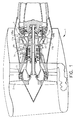
- FIG. 1 is a diagrammatic view of an aircraft high bypass turbofan gas turbine engine having a turbine rotor clearance control system in accordance with the present invention.
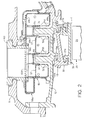
- FIG. 2 is a cross-sectional view of a counterflowing thermal clearance control system for a stator assembly in the turbine section of the gas turbine engine in FIG. 1.
- FIG. 3 is a partial cutaway perspective view, forward looking aft, of the manifolds and spray tubes of the clearance control system for the engine and stator assembly shown in FIGS. 1 and 2.
- FIG. 4 is an exploded perspective view of the manifold and counterflowing means of the thermal clearance control system shown in FIG. 2.
- FIG. 5 is a partial perspective view of the manifolds and spray tubes of an alternate embodiment of the clearance control system shown in FIG. 3.
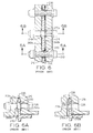
- FIG. 6 is a top planform view of a prior art flange assembly for a thermal control system.
- FIG. 6a is a side cutaway view of the prior art flange assembly taken through section AA in FIG. 6.
- FIG. 6b is a side cutaway view of the prior art flange assembly taken through section BB in FIG. 6.
- FIG. 1 illustrates a typical gas turbine engine 1 such as a CFM56 series engine having in serial flow relationship a fan 2, a booster or low pressure compressor (LPC) 3, a high pressure compressor (HPC) 4, a combustion section 5, a high pressure turbine (HPT) 6, and a low pressure turbine (LPT) 7.
- a high pressure shaft drivingly connects HPT 6 to HPC 4 and a low pressure shaft 8 drivingly connects LPT 7 to LPC 3 and fan 2.
- HPT 6 includes an HPT rotor 20 having turbine blades 24 mounted at a periphery of rotor 20.
- a midstage air supply 9a and a high stage air supply 9b are used as sources for thermal control air flow which is supplied to a turbine blade clearance control apparatus generally shown at 10 through upper and lower thermal control air supply tubes 11a and 11b respectively.
- Turbine blade clearance control apparatus 10 including counterflowing upper manifold 58a and lower manifold 58b, illustrates one form of the preferred embodiment of a counterflowing thermal control apparatus of the present invention and is illustrated in greater detail in FIGS. 2 and 3.
- turbine blade clearance control apparatus 10 is illustrated using upper manifold 58a radially disposed between an annular inner casing 12 and an outer casing 14.
- a stator assembly generally shown at 13 is attached to inner casing 12 by forward and aft case hook means 15a and 15b respectively.
- Stator assembly 13 includes an annular stator shroud 26, preferably segmented, mounted by shroud hook means 27a and 27b to a preferably segmented shroud support 30.
- Shroud 26 circumscribes turbine blades 24 of rotor 20 and is used to prevent the flow from leaking around the radial outer tip of blade 24 by minimizing the radial blade tip clearance T.
- thermal control rings 32 and 34 are provided. Thermal control rings 32 and 34 are associated with inner casing 12 and may be integral with the respective casing (as illustrated in FIG 2), may be bolted to or otherwise fastened to the casing, or may be mechanically isolated from but in sealing engagement with the casing. In each embodiment control rings provide thermal control mass to more effectively move shroud 26 radially inward and outward to adjust clearance T.
- the embodiment illustrated in FIG. 2 uses thermal control air from stages of HPC 4 in FIG. 1 to cool or heat rings 32 and 34.
- the present invention supplies thermal control air through a set of counterflowing spray tubes having impingement apertures 50 to cool each axially extending annular section of casing that for the embodiment in FIG. 2 is illustrated by thermal control rings 32 and 34.
- a heat transfer fluid flowpath in a first circumferential direction is indicated by ⁇ and its corresponding counterflowing flowpath is indicated by in FIG. 2.
- FIG. 3 illustrates the preferred embodiment of the present invention as having two essentially 180° annular counterflowing spray tubes such as an upper forward spray tube 44a and a lower forward spray tube 44b that are used to form a first continuous 360° heat transfer flowpath X flowing in a first circumferential direction.
- An upper center spray tube 46a and a lower center spray tube 46b forms a second continuous 360° heat transfer flowpath Y flowing in a second circumferential direction.
- X and Y comprise a counterflowing thermal control means that provides substantially uniform mass flowrate weighted average heat transfer along the combined heat transfer flowpath assuming that impingement apertures 50 are sized accordingly, by means well known in the art, which in the the preferred embodiment is evenly.
- Each of the spray tubes in one of either first or second flowpaths X and Y respectively are supplied with thermal control air by different manifolds, top manifold 58a and bottom manifold 58b, in the same circumferential direction (clockwise or counterclockwise). Therefore, upper manifold 58a supplies thermal control air to upper forward spray tube 44a and upper aft spray tube 48a in the clockwise direction and to upper center spray tube 46a in the counterclockwise direction. Similarly, lower manifold 58b supplies thermal control air to lower forward spray tube 44b and lower aft spray tube 48b in the clockwise direction and to lower center spray tube 46b in the counterclockwise direction.
- FIG. 2 The flowpath and manifold cross-sectional view FIG. 2 is taken through upper manifold 58a of FIG. 3. Referring back to FIG. 2; shown are upper forward spray tube 44a, lower centerspray tube 46b, and upper aft spray tube 48a wherein upper forward and aft spray tubes 44a and 48a provide thermal control air for control rings 32 and 34 and lower center spray tube 46b provides ⁇ thermal control air for the rings. Impingement apertures 50 provide an impingement means to thermally control rings 32 and 34 in a targeted and efficient manner.
- An upper thermal control air plenum generally indicated by 56a is provided within upper manifold 58a for supplying thermal control air to upper forward and aft spray tubes 44a and 48a.
- Upper thermal control air plenum 56a also supplies thermal control air to upper center spray tube 46a (shown in FIGS. 3 and 4).
- a boss 60 opens to thermal control air plenum 56a providing a connection for a thermal control air supply tube 11a as shown in FIG. 1.
- FIG. 3 a perspective diagrammatic view is shown of a thermal control air manifold means and flowpaths of the preferred embodiment employing two oppositely disposed upper and lower manifolds 58a and 58b that receive thermal control air from corresponding upper and lower thermal control air supply tubes 11a and 11b.
- Upper manifold 58a supplies thermal control air to corresponding upper forward, center, and aft spray tubes 44a, 46a, and 48a respectively.
- Lower manifolds 58b supplies thermal control air to corresponding lower forward, center, and aft spray tubes 44b, 46b, and 48b respectively.
- Forward and aft spray tubes, supplied by one manifold are disposed in a first 180° sector, R or L on either side of center reference line C and the center spray tube supplied by the same manifold lies in the corresponding opposite 180° sector.
- the spray tubes have inlets I at their corresponding supply manifolds and plugs P near the corresponding opposite manifold such that each spray tube essentially provides a 180° heat transfer fluid flowpath that flows in one circumferential direction.
- Spray tubes include impingement apertures 50 so that each set of adjacent spray tubes, forward and center set and aft and center set, in each sector provide a set of counterflowing heat transfer flowpaths and means for effecting heat transfer (cooling in the illustrated embodiments) between rings 32 and 34 of inner casing 12 and the heat transfer fluid.
- the flowpaths within the spray tubes are manifolded to provide parallel counterflowing heat transfer flowpaths that have the same temperature thermal control air (heat transfer fluid) supplied from their corresponding supply manifolds 58a and 58b.
- the temperature drop from inlet I to plug P is substantially the same but in opposite circumferential directions in each set of counterflowing flowpaths. Therefore at any point around inner case 12, control ring 32 or 34 is being impinged by thermal control air having the same mass flowrate weighted average temperature from each one of the set of counterflowing spray tube flowpaths, assuming mass flow rates through respective impingement apertures 50 are the same in each set of spray tubes.
- FIG. 4 illustrates, in greater detail, one embodiment of the construction of manifold 58a.
- Scalloped out openings 49a, 49b, and 49c in upper forward, center, and aft spray tubes 44a, 46a, and 48a respectively provide a thermal control airflow passage into these spray tubes fed by manifold 58a through respective inlets I in FIG. 3.
- Side caps 53 and inverted wall channels 55 are contoured to fit between and are attached, preferably brazed, to adjoining spray tubes.
- Baffles 57 in the form of inverted channels are disposed in scalloped out openings 49a and 49b to minimize pressure losses associated with the system by preventing direct discharge of thermal control air into tubes 44a and 46b from boss 60 mounted in a top cover 61 of manifold 58a.
- Bottom manifold 58b is constructed in a similar manner.
- Upper forward and aft spray tubes 44a and 48a respectively meet and are in abutting relationship with their corresponding lower forward and aft spray tubes 44b and 48b at their respective upper ends 51a and 51c.
- Upper center spray tube 46a is placed in the same relationship with its corresponding lower center spray tube 46b (not shown) near its end 46e thereby forming substantially continuous heat transfer circuits of thermal control air.
- FIG. 5 An alternative embodiment, illustrated in FIG. 5, provides an alternative turbine blade clearance control apparatus generally shown at 110 having sets of counterflowing flowpaths that are in serial flow relationship.
- An upper thermal control air plenum 158a effective to receive thermal control air from upper thermal control air supply tube 11a, is in fluid supply communication with the middles of semi-circular upper forward spray tube 144a and upper aft spray tube 148a so as to cause the thermal control air to flow in opposite circumferential directions indicated by clockwise arrow 150 and counterclockwise arrow 151.
- a lower thermal control air plenum 158b effective to receive thermal control air from lower thermal control air supply tube 11b, is in fluid supply communication with the middles of semi-circular lower forward spray tube 144b and lower aft spray tube 148b so as to cause the thermal control air to flow in opposite circumferential directions indicated by clockwise arrow 150 and counterclockwise arrow 151.
- An upper right center spray tube 146UR extends throughs 90° terminating at an end s and is in serial flow receiving communication with corresponding upper forward spray tube 144a and upper aft spray tube 148a by way of dual thermal control air transfer tube 160UR while an upper left center spray tube 146UL extends throughs 90° terminating at an end s and is in serial flow receiving communication with corresponding upper forward spray tube 144a and upper aft spray tube 148a by way of dual thermal control air transfer tube 160UL.
- a lower right center spray tube 146LR extends throughs 90° terminating at an end s and is in serial flow receiving communication with corresponding lower forward spray tube 144b and lower aft spray tube 148b by way of dual thermal control air transfer tube 160LR while a lower left center spray tube 146LL extends throughs 90° terminating at an end s and is in serial flow receiving communication with corresponding lower forward spray tube 144b and lower aft spray tube 148b by way of dual thermal control air transfer tube 160LL.
- Impingemnet apertures 50 are disposed in spray tubes for impinging thermal control air on thermal control rings 32 and 34.
- This arrangement provides two sets of serial type counterflowing heat transfer flowpaths for each of four quadrants of engine casing 12 for impinging thermal control air on forward and aft rings 32 and 34 in order to control their thermal growth and shrinkage.
- the average temperature of thermal control air impinged on the casing is lower because the temperature drop across the flowpath is greater than that of the drop across the parallel flowpaths shown in FIGS. 2 and 3.
- the mass flowrate weighted average temperature should be substantially the same around the rings or other sections of casing to be thermally controlled.
- the mass flowrate of heat transfer fluid or thermal control air must be the same through all the impingement apertures. Therefore the cross-sectional area of the spray tubes and their impingement apertures must be carefully designed and sized, keeping in mind that the velocity of the thermal control air as it travels downstream through the spray tube decreases and its static pressure increases.
- a constant cross-sectional area for the spray tube and a constant impingement aperture area may be used if the ratio is chosen correctly. It has been found that a thermal control air velocity through the spray tubes of between Mach Number .1 to .05, having a total to static pressure ratio (p T /p S ) of about 1.00, is preferable. Alternatively a circumferentially varying impingement aperture width or density may be used to maintain a uniform mass flow rate for impingement thermal control.
Landscapes
- Engineering & Computer Science (AREA)
- Mechanical Engineering (AREA)
- General Engineering & Computer Science (AREA)
- Physics & Mathematics (AREA)
- Thermal Sciences (AREA)
- Turbine Rotor Nozzle Sealing (AREA)
Abstract
Description
- The invention relates to thermal control of gas turbine engine cases and particularly for thermal control of clearances between turbine rotors and surrounding shrouds.
- Rotor clearance control systems that incorporate heating and cooling to effect thermal control of shrinkage and expansion of different parts of gas turbine engine cases are used for aircraft gas turbine engines to reduce leakage losses and improve specific fuel (SFC) consumption of the engines. One example of such an apparatus can be found described in U.S. Patent No. 4,826,397, entitled "Stator Assembly for a Gas Turbine Engine", by Paul S. Shook and Daniel E. Kane. Reference may be had to this patent, by Shook et al, for background information and, for this reason, it is incorporated herein by reference. Shook discloses a clearance control system that uses spray tubes that spray air ducted from the engine's fan or compressor to cool turbine engine case rings in order to thermally control the clearance between an engine turbine rotor section and a corresponding stator section shroud disposed around the turbine rotor section. The Shook patent attempts to control circumferential thermal gradients around the rings, or rails as they are referred to in the patent, by shielding and insulating the rails. The shielding does not eliminate the circumferential gradient but does reduce the magnitude and severity of the gradient and therefore the stress and clearance variation that such a severe circumferential thermal gradient causes.
- However spray tubes behave as heat exchangers and a circumferential variation in the temperature of the heat transfer fluid cannot be avoided nor the attendant problems associated with such a circumferential variation as shown in the prior art. The circumferential variation in the temperature of the air used to thermally control the rings produces unequal expansion and contraction of the rings particularly during transient operation of the engine such as during take-off.
- The circumferential temperature variation produces a mechanical distortion of the engine casing or rings associated with the casing commonly referred to as an out of round condition. Such out of round conditions further leads to increased rubbing of the rotor and its corresponding stator assemblies such as between rotor blades and surrounding stator shrouds or between rotating and static seal assemblies. The out of round condition causes increased operating clearances, reduced engine performance, a deteriorating engine performance, and reduced component efficiency. Often difficult and expensive machining of circumferential variations in the static parts is employed during the manufacturing of the casing components to compensate for the operational circumferential variations in the thermal control air.
- Another example of a clearance control system is found described in U.S. Patent No. 4,363,599, entitled "Clearance Control", by Larry D. Cline et al assigned to General Electric the assignee of the present invention, that discloses the use of control rings integrated into the turbine casing and supporting a turbine shroud that surround and seals about turbine rotor blades. Thermal control air is supplied to the rings to effect thermally induced clearance control between the turbine blade tips and the surrounding shroud. Thermal control air is supplied to the rings from an area surrounding the combustor and through axial extending passages in the casing and through the rings.
- A General Electric CF6-80C2 turbofan gas turbine engine incorporates a case flange assembly as depicted in FIGS. 6, 6a, and 6b, labelled as prior art, having a turbine shroud
thermal control ring 220 bolted between acompressor case flange 210 and aturbine case flange 216.Compressor flange 210 andturbine flange 216 have compressor and turbine flangecooling air grooves thermal control ring 220. Cooling air is fed into compressor flangecooling air groove 260a through aradial inlet slot 270a which is cut throughcompressor flange 210 to groove 260a. - Compressor and turbine flanges have
bolt holes 226 which snugly receivebolts 240.Control ring 220 has alternatingbolt holes 226 and enlargedbolts holes 230 that provides a cooling air passage throughcontrol ring 220 to turbine flangecooling air groove 260b. Radial coolingair exhaust slots 270b provide an exit for the cooling air from the flange assembly. - There are 34 bolt holes around the engine flange assembly and 17 sets of radial slots providing cooling air passages for thermal control around the ring. Cooling air is fed to the grooves at different circumferential locations thereby subject to circumferential variations in the cooling air temperature.
- The present invention provides a means to thermally control a section of engine casing by counterflowing two heat transfer fluid flowpaths in heat transfer communication with the section of engine casing. The flowpaths may be in parallel or series such that there is substantially no circumferential gradient in the mass flowrate weighted average temperature of the heat transfer fluid supplied by the two counterflowing fluid flowpaths. An embodiment employs forward and aft rings associated with the engine casing (the rings may be attached to the casing by bolts, welding or some other fastening means or be integral with the casing) that supports corresponding forward and aft ends of a stator assembly that may be circumferentially segmented.
- One embodiment of the present invention illustrated herein provides a means for impinging cooling air onto forward and aft rings by three spray tubes in each of two 180° sectors wherein the forward and aft spray tubes have cooling air flowing in one circumferential direction and the middle spray tubes flow cooling air in an opposite circumferential direction. The middle spray tubes include impingement apertures and have sufficient flow capacity to impinge cooling air on both rings and the forward and aft spray tubes include impingement apertures to impinge cooling air onto the corresponding forward and aft rings. Two manifolds are used to supply the spray tubes wherein each manifold provides a means to counterflow thermal control air by supplying either the middle or the forward and aft spray tubes in opposite sectors and in opposite circumferential flow directions.
- A preferred embodiment of the present invention substantially eliminates any circumferential temperature variation of the gas turbine engine cases and associated rings used to support stator assemblies by using two circumferentially counterflowing flowpaths in which the mass flowrate weighted average temperature of the heat transfer fluid in two flowpaths at any point around the case is substantially the same.
- This advantage substantially reduces or eliminates out of round conditions and circumferential stresses found in thermally controlled cases having variations in their heat transfer fluid on the order of as little as 50-100°F around the case.
- The preferred embodiment of the present invention reduces operating clearances by minimizing rubbing between rotor blade tips and corresponding stator assemblies thereby; improving engine performance, reducing the rate of engine performance deterioration, and improving component efficiency.
- The preferred embodiment of the present invention provides a further advantage by allowing gas turbine engines to be designed with tighter blade tip operating clearances thereby improving the engine's design fuel efficiency.
- The invention is explained in the following illustrative description, taken in connection with the accompanying drawings where:
- FIG. 1 is a diagrammatic view of an aircraft high bypass turbofan gas turbine engine having a turbine rotor clearance control system in accordance with the present invention.
- FIG. 2 is a cross-sectional view of a counterflowing thermal clearance control system for a stator assembly in the turbine section of the gas turbine engine in FIG. 1.
- FIG. 3 is a partial cutaway perspective view, forward looking aft, of the manifolds and spray tubes of the clearance control system for the engine and stator assembly shown in FIGS. 1 and 2.
- FIG. 4 is an exploded perspective view of the manifold and counterflowing means of the thermal clearance control system shown in FIG. 2.
- FIG. 5 is a partial perspective view of the manifolds and spray tubes of an alternate embodiment of the clearance control system shown in FIG. 3.
- FIG. 6 is a top planform view of a prior art flange assembly for a thermal control system.
- FIG. 6a is a side cutaway view of the prior art flange assembly taken through section AA in FIG. 6.
- FIG. 6b is a side cutaway view of the prior art flange assembly taken through section BB in FIG. 6.
- FIG. 1 illustrates a typical gas turbine engine 1 such as a CFM56 series engine having in serial flow relationship a
fan 2, a booster or low pressure compressor (LPC) 3, a high pressure compressor (HPC) 4, acombustion section 5, a high pressure turbine (HPT) 6, and a low pressure turbine (LPT) 7. A high pressure shaft drivingly connects HPT 6 to HPC 4 and a low pressure shaft 8 drivingly connects LPT 7 toLPC 3 andfan 2. HPT 6 includes anHPT rotor 20 havingturbine blades 24 mounted at a periphery ofrotor 20. Amidstage air supply 9a and a highstage air supply 9b (typically drawing air from 4th and 9th stages respectively of HPC 4 in a CFM56 engine) are used as sources for thermal control air flow which is supplied to a turbine blade clearance control apparatus generally shown at 10 through upper and lower thermal controlair supply tubes clearance control apparatus 10, including counterflowingupper manifold 58a andlower manifold 58b, illustrates one form of the preferred embodiment of a counterflowing thermal control apparatus of the present invention and is illustrated in greater detail in FIGS. 2 and 3. - Referring now to FIG. 2, turbine blade
clearance control apparatus 10 is illustrated usingupper manifold 58a radially disposed between an annularinner casing 12 and anouter casing 14. A stator assembly generally shown at 13 is attached toinner casing 12 by forward and aft case hook means 15a and 15b respectively.Stator assembly 13 includes anannular stator shroud 26, preferably segmented, mounted by shroud hook means 27a and 27b to a preferably segmentedshroud support 30. Shroud 26circumscribes turbine blades 24 ofrotor 20 and is used to prevent the flow from leaking around the radial outer tip ofblade 24 by minimizing the radial blade tip clearance T. - It is well known in the industry that small turbine blade tip clearances provide lower operational specific fuel consumption (SFC) and thus large fuel savings. In order to more effectively control clearance T with a minimal amount of time lag and thermal control (cooling or heating depending on operating conditions) air flow, forward and aft
thermal control rings Thermal control rings inner casing 12 and may be integral with the respective casing (as illustrated in FIG 2), may be bolted to or otherwise fastened to the casing, or may be mechanically isolated from but in sealing engagement with the casing. In each embodiment control rings provide thermal control mass to more effectively moveshroud 26 radially inward and outward to adjust clearance T. - The embodiment illustrated in FIG. 2 uses thermal control air from stages of HPC 4 in FIG. 1 to cool or
heat rings impingement apertures 50 to cool each axially extending annular section of casing that for the embodiment in FIG. 2 is illustrated bythermal control rings in FIG. 2.
- FIG. 3 illustrates the preferred embodiment of the present invention as having two essentially 180° annular counterflowing spray tubes such as an upper
forward spray tube 44a and a lower forward spray tube 44b that are used to form a first continuous 360° heat transfer flowpath X flowing in a first circumferential direction. An uppercenter spray tube 46a and a lowercenter spray tube 46b forms a second continuous 360° heat transfer flowpath Y flowing in a second circumferential direction. Together X and Y comprise a counterflowing thermal control means that provides substantially uniform mass flowrate weighted average heat transfer along the combined heat transfer flowpath assuming thatimpingement apertures 50 are sized accordingly, by means well known in the art, which in the the preferred embodiment is evenly. - Each of the spray tubes in one of either first or second flowpaths X and Y respectively are supplied with thermal control air by different manifolds,
top manifold 58a andbottom manifold 58b, in the same circumferential direction (clockwise or counterclockwise). Therefore,upper manifold 58a supplies thermal control air to upperforward spray tube 44a and upperaft spray tube 48a in the clockwise direction and to uppercenter spray tube 46a in the counterclockwise direction. Similarly,lower manifold 58b supplies thermal control air to lower forward spray tube 44b and loweraft spray tube 48b in the clockwise direction and to lowercenter spray tube 46b in the counterclockwise direction. - The flowpath and manifold cross-sectional view FIG. 2 is taken through
upper manifold 58a of FIG. 3. Referring back to FIG. 2; shown are upperforward spray tube 44a,lower centerspray tube 46b, and upperaft spray tube 48a wherein upper forward andaft spray tubes thermal control air for control rings 32 and 34 and lower
center spray tube 46b provides ⊕ thermal control air for the rings.Impingement apertures 50 provide an impingement means to thermally control rings 32 and 34 in a targeted and efficient manner. - An upper thermal control air plenum generally indicated by 56a is provided within
upper manifold 58a for supplying thermal control air to upper forward andaft spray tubes control air plenum 56a also supplies thermal control air to uppercenter spray tube 46a (shown in FIGS. 3 and 4). Aboss 60 opens to thermalcontrol air plenum 56a providing a connection for a thermal controlair supply tube 11a as shown in FIG. 1. - Referring now to FIG. 3, a perspective diagrammatic view is shown of a thermal control air manifold means and flowpaths of the preferred embodiment employing two oppositely disposed upper and
lower manifolds air supply tubes Upper manifold 58a supplies thermal control air to corresponding upper forward, center, andaft spray tubes Lower manifolds 58b supplies thermal control air to corresponding lower forward, center, andaft spray tubes - The spray tubes have inlets I at their corresponding supply manifolds and plugs P near the corresponding opposite manifold such that each spray tube essentially provides a 180° heat transfer fluid flowpath that flows in one circumferential direction. Spray tubes include
impingement apertures 50 so that each set of adjacent spray tubes, forward and center set and aft and center set, in each sector provide a set of counterflowing heat transfer flowpaths and means for effecting heat transfer (cooling in the illustrated embodiments) betweenrings inner casing 12 and the heat transfer fluid. - As can readily be seen in FIG. 3 the flowpaths within the spray tubes are manifolded to provide parallel counterflowing heat transfer flowpaths that have the same temperature thermal control air (heat transfer fluid) supplied from their
corresponding supply manifolds inner case 12,control ring respective impingement apertures 50 are the same in each set of spray tubes. - For example suppose air is supplied at 400°F to the manifold and has a 50°F drop along the circumferential length of the spray tubes through its corresponding 180° sector. The mass flowrate weighted average temperature sprayed on the casing and control ring would be 375°F at any circumferential location being cooled. On the other hand if the heat transfer fluid was not counterflowed and only one inlet feed manifold was used, there would be a maxiumum temperature gradient from 400°F to 350°F between opposite ends of the spray tubes.
- It can be readily seen that if the circumferential variation in the two adjoining spray tubes would be different then mass flow rates of thermal control air impinging the rings could be adjusted to obtain a substantially constant mass flow rate weighted average temperature of the thermal control air used for impingement around the thermal control ring.
- FIG. 4 illustrates, in greater detail, one embodiment of the construction of
manifold 58a. Scalloped outopenings aft spray tubes manifold 58a through respective inlets I in FIG. 3. Side caps 53 andinverted wall channels 55, preferably made of sheet metal, are contoured to fit between and are attached, preferably brazed, to adjoining spray tubes. Baffles 57 in the form of inverted channels are disposed in scalloped outopenings tubes boss 60 mounted in atop cover 61 ofmanifold 58a.Bottom manifold 58b is constructed in a similar manner. - Upper forward and
aft spray tubes aft spray tubes 44b and 48b at their respective upper ends 51a and 51c. Uppercenter spray tube 46a is placed in the same relationship with its corresponding lowercenter spray tube 46b (not shown) near itsend 46e thereby forming substantially continuous heat transfer circuits of thermal control air. - An alternative embodiment, illustrated in FIG. 5, provides an alternative turbine blade clearance control apparatus generally shown at 110 having sets of counterflowing flowpaths that are in serial flow relationship. An upper thermal control air plenum 158a, effective to receive thermal control air from upper thermal control
air supply tube 11a, is in fluid supply communication with the middles of semi-circular upper forward spray tube 144a and upperaft spray tube 148a so as to cause the thermal control air to flow in opposite circumferential directions indicated byclockwise arrow 150 andcounterclockwise arrow 151. Similarly a lower thermalcontrol air plenum 158b, effective to receive thermal control air from lower thermal controlair supply tube 11b, is in fluid supply communication with the middles of semi-circular lowerforward spray tube 144b and loweraft spray tube 148b so as to cause the thermal control air to flow in opposite circumferential directions indicated byclockwise arrow 150 andcounterclockwise arrow 151. - An upper right center spray tube 146UR extends throughs 90° terminating at an end s and is in serial flow receiving communication with corresponding upper forward spray tube 144a and upper
aft spray tube 148a by way of dual thermal control air transfer tube 160UR while an upper left center spray tube 146UL extends throughs 90° terminating at an end s and is in serial flow receiving communication with corresponding upper forward spray tube 144a and upperaft spray tube 148a by way of dual thermal control air transfer tube 160UL. A lower right center spray tube 146LR extends throughs 90° terminating at an end s and is in serial flow receiving communication with corresponding lowerforward spray tube 144b and loweraft spray tube 148b by way of dual thermal control air transfer tube 160LR while a lower left center spray tube 146LL extends throughs 90° terminating at an end s and is in serial flow receiving communication with corresponding lowerforward spray tube 144b and loweraft spray tube 148b by way of dual thermal control air transfer tube 160LL.Impingemnet apertures 50 are disposed in spray tubes for impinging thermal control air on thermal control rings 32 and 34. - This arrangement provides two sets of serial type counterflowing heat transfer flowpaths for each of four quadrants of
engine casing 12 for impinging thermal control air on forward and aft rings 32 and 34 in order to control their thermal growth and shrinkage. The average temperature of thermal control air impinged on the casing is lower because the temperature drop across the flowpath is greater than that of the drop across the parallel flowpaths shown in FIGS. 2 and 3. - As noted earlier the mass flowrate weighted average temperature should be substantially the same around the rings or other sections of casing to be thermally controlled. In order for this optimum condition to be met the mass flowrate of heat transfer fluid or thermal control air must be the same through all the impingement apertures. Therefore the cross-sectional area of the spray tubes and their impingement apertures must be carefully designed and sized, keeping in mind that the velocity of the thermal control air as it travels downstream through the spray tube decreases and its static pressure increases.
- A constant cross-sectional area for the spray tube and a constant impingement aperture area may be used if the ratio is chosen correctly. It has been found that a thermal control air velocity through the spray tubes of between Mach Number .1 to .05, having a total to static pressure ratio (pT/pS) of about 1.00, is preferable. Alternatively a circumferentially varying impingement aperture width or density may be used to maintain a uniform mass flow rate for impingement thermal control.
- While the preferred embodiment of our invention has been described fully in order to explain its principles, it is understood that various modifications or alterations may be made to the preferred embodiment without departing from the invention.
Claims (13)
- A thermal control apparatus for a gas turbine engine casing, said thermal control apparatus comprising;
at least two axially spaced apart circumferentially disposed continuous flowpaths in heat transfer communication with an axially extending section of the casing,
a means of counterflowing a heat transfer fluid through said flowpaths such that said fluid in one flowpath flows in a clockwise direction and said fluid in the other of said flowpaths flows in a counterclockwise direction, and
a means for effecting heat transfer between said fluid and said casing section. - A thermal control apparatus as claimed in claim 1 wherein said flowpaths are in series fluid flow communication.
- A thermal control apparatus as claimed in claim 2 wherein said flowpaths are in parallel fluid flow communication.
- A thermal control apparatus as claimed in claim 3 wherein said counterflowing means comprises an axially extending manifold having clockwise and counterclockwise facing inlets in fluid supply communication with corresponding ones of said clockwise and counterclockwise flowing flow paths.
- A thermal control apparatus as claimed in claim 4 further comprising two manifolds supplying two corresponding sets of said counterflowing flowpaths.
- A thermal control apparatus as claimed in claim 5 further comprising two sectors about the engine casing wherein each of said manifolds supplies said fluid to flowpaths in each of said sectors such that one of said manifolds supplies said clockwise flowing flowpaths and the other of said manifolds supplies said counterclockwise flowing flowpaths extending through each one of said sectors.
- A thermal control apparatus as claimed in claim 6 further comprising at least one annular thermal control ring associated with said section of the engine casing axially disposed between said set of said counterflowing flowpaths and a support means tying an annular stator assembly to said thermal control ring such that expansion and contraction of said thermal control ring will cause a corresponding expansion and contraction of said stator assembly.
- A thermal control apparatus as claimed in claim 7 wherein said stator assembly comprises a segmented annular stator shroud.
- A thermal control apparatus as claimed in claim 8 wherein said means for effecting heat transfer between said heat transfer fluid and said casing is by impingement and comprises circumferentially disposed spray tubes containing said flowpaths and impingement apertures in said spray tubes arranged to impinge said Fluid onto said thermal control ring to effect thermal control of said thermal control ring.
- A thermal control apparatus as claimed in claim 6 further comprising:
forward and aft axially spaced apart thermal control rings associated with said section of the engine casing,
a first set and second set of two axially spaced apart circumferentially disposed counterflowing continuous heat transfer flowpaths in heat transfer communication with an axially extending section of the casing,
said first and second sets of counterflowing continuous heat transfer flowpaths comprise three axially spaced apart circumferentially disposed counterflowing continuous heat transfer flowpaths interdigitated with said thermal control rings
a support means tying forward and aft ends of an annular stator assembly to corresponding ones of said forward and aft thermal control rings such that expansion and contraction of said thermal control rings will cause a corresponding expansion and contraction of said stator assembly,
said means of counterflowing comprises a means to flow heat transfer fluid through said first and third heat transfer flowpaths in a first circumferential direction and through said second heat transfer flowpath in a second counterflowing direction, and
said first and second heat transfer flowpaths are arranged to effect heat transfer between heat transfer fluid and said first thermal control ring and said third and second flowpaths are arranged to effect heat transfer between heat transfer fluid and said second thermal control ring. - A thermal control apparatus as claimed in claim 10 wherein said stator assembly comprises a segmented annular stator shroud.
- A thermal control apparatus as claimed in claim 11 wherein said means for effecting heat transfer between said heat transfer fluid and said rings comprises circumferentially disposed spray tubes containing said flowpaths and impingement apertures in said spray tubes arranged to spray said fluid onto said thermal control rings to effect thermal control of said thermal control rings.
- A gas turbine engine comprising;
an annular engine casing surrounding a portion of the engine's rotor,
at least two axially spaced apart circumferentially disposed flowpaths in heat transfer communication with an axially extending section of the casing,
a means of counterflowing air through said flowpaths such that the air in one flowpath flows in a clockwise direction and the air in the other of said flowpaths flows in a counterclockwise direction,
a compressor means and a means for supplying air from said compressor to said means of counterflowing air, and
a means for effecting heat transfer between air and said casing section.
Applications Claiming Priority (2)
| Application Number | Priority Date | Filing Date | Title |
|---|---|---|---|
| US787498 | 1991-11-04 | ||
| US07/787,498 US5205115A (en) | 1991-11-04 | 1991-11-04 | Gas turbine engine case counterflow thermal control |
Publications (2)
| Publication Number | Publication Date |
|---|---|
| EP0541325A1 true EP0541325A1 (en) | 1993-05-12 |
| EP0541325B1 EP0541325B1 (en) | 1997-05-07 |
Family
ID=25141678
Family Applications (1)
| Application Number | Title | Priority Date | Filing Date |
|---|---|---|---|
| EP92310045A Expired - Lifetime EP0541325B1 (en) | 1991-11-04 | 1992-11-03 | Gas turbine engine case thermal control |
Country Status (5)
| Country | Link |
|---|---|
| US (1) | US5205115A (en) |
| EP (1) | EP0541325B1 (en) |
| JP (1) | JPH06102987B2 (en) |
| CA (1) | CA2077842C (en) |
| DE (1) | DE69219557T2 (en) |
Cited By (21)
| Publication number | Priority date | Publication date | Assignee | Title |
|---|---|---|---|---|
| EP0638727A1 (en) * | 1993-08-14 | 1995-02-15 | ABB Management AG | Compressor and its method of operation |
| EP0892153A1 (en) * | 1997-07-18 | 1999-01-20 | Societe Nationale D'etude Et De Construction De Moteurs D'aviation "Snecma" | Heating or cooling device for carter with a circular section |
| EP0892152A1 (en) * | 1997-07-18 | 1999-01-20 | Societe Nationale D'etude Et De Construction De Moteurs D'aviation "Snecma" | Heating or cooling device for a carter with circular section |
| EP1505261A1 (en) * | 2003-08-06 | 2005-02-09 | Snecma Moteurs | Device to control clearances in a gas turbine |
| EP1555394A1 (en) * | 2004-01-16 | 2005-07-20 | Snecma Moteurs | Device to control clearances in a gas turbine |
| EP1577502A1 (en) * | 2004-03-18 | 2005-09-21 | Snecma | Spraybar configuration to control the tip clearance in a gas turbine |
| EP1609954A1 (en) * | 2004-06-23 | 2005-12-28 | Rolls-Royce Plc | Securing arrangement |
| WO2007012305A1 (en) * | 2005-07-29 | 2007-02-01 | Mtu Aero Engines Gmbh | Apparatus for active gap monitoring for a continuous flow machine |
| EP1914392A2 (en) * | 2006-10-12 | 2008-04-23 | General Electric Company | Turbine case impingement cooling for heavy duty gas turbines |
| EP2025878A2 (en) * | 2007-08-03 | 2009-02-18 | General Electric Company | Aircraft gas turbine engine blade tip clearance control |
| FR2949808A1 (en) * | 2009-09-08 | 2011-03-11 | Snecma | PILOTAGE OF THE AUBES IN A TURBOMACHINE |
| US8038388B2 (en) | 2007-03-05 | 2011-10-18 | United Technologies Corporation | Abradable component for a gas turbine engine |
| WO2013001246A1 (en) * | 2011-06-30 | 2013-01-03 | Snecma | Arrangement for connecting a duct to an air-distribution casing |
| RU2477802C2 (en) * | 2008-04-21 | 2013-03-20 | Сименс Акциенгезелльшафт | Steam turbine with cooling device |
| US8403637B2 (en) | 2009-04-08 | 2013-03-26 | Rolls-Royce Plc | Thermal control system for turbines |
| WO2013184336A1 (en) | 2012-06-08 | 2013-12-12 | United Technologies Corporation | Active clearance control for gas turbine engine |
| EP2236750A3 (en) * | 2009-03-11 | 2014-12-10 | Rolls-Royce plc | An impingement cooling arrangement for a gas turbine engine |
| US8967951B2 (en) | 2012-01-10 | 2015-03-03 | General Electric Company | Turbine assembly and method for supporting turbine components |
| CN105026693A (en) * | 2013-03-13 | 2015-11-04 | 西门子股份公司 | Turbine engine temperature control system with heating element for a gas turbine engine |
| EP2587028A3 (en) * | 2011-10-31 | 2017-07-19 | General Electric Company | Active clearance control system and method for a gas turbine engine |
| EP3232014A1 (en) * | 2016-04-08 | 2017-10-18 | United Technologies Corporation | Thermal lifting member for blade outer air seal support |
Families Citing this family (62)
| Publication number | Priority date | Publication date | Assignee | Title |
|---|---|---|---|---|
| US5375973A (en) * | 1992-12-23 | 1994-12-27 | United Technologies Corporation | Turbine blade outer air seal with optimized cooling |
| US5391052A (en) * | 1993-11-16 | 1995-02-21 | General Electric Co. | Impingement cooling and cooling medium retrieval system for turbine shrouds and methods of operation |
| US5486090A (en) * | 1994-03-30 | 1996-01-23 | United Technologies Corporation | Turbine shroud segment with serpentine cooling channels |
| US5439348A (en) * | 1994-03-30 | 1995-08-08 | United Technologies Corporation | Turbine shroud segment including a coating layer having varying thickness |
| US5423659A (en) * | 1994-04-28 | 1995-06-13 | United Technologies Corporation | Shroud segment having a cut-back retaining hook |
| US5480281A (en) * | 1994-06-30 | 1996-01-02 | General Electric Co. | Impingement cooling apparatus for turbine shrouds having ducts of increasing cross-sectional area in the direction of post-impingement cooling flow |
| US5591002A (en) * | 1994-08-23 | 1997-01-07 | General Electric Co. | Closed or open air cooling circuits for nozzle segments with wheelspace purge |
| US5634766A (en) * | 1994-08-23 | 1997-06-03 | General Electric Co. | Turbine stator vane segments having combined air and steam cooling circuits |
| US5538393A (en) * | 1995-01-31 | 1996-07-23 | United Technologies Corporation | Turbine shroud segment with serpentine cooling channels having a bend passage |
| US5685693A (en) * | 1995-03-31 | 1997-11-11 | General Electric Co. | Removable inner turbine shell with bucket tip clearance control |
| US5639210A (en) * | 1995-10-23 | 1997-06-17 | United Technologies Corporation | Rotor blade outer tip seal apparatus |
| US6626635B1 (en) * | 1998-09-30 | 2003-09-30 | General Electric Company | System for controlling clearance between blade tips and a surrounding casing in rotating machinery |
| US6185925B1 (en) | 1999-02-12 | 2001-02-13 | General Electric Company | External cooling system for turbine frame |
| JP4274666B2 (en) * | 2000-03-07 | 2009-06-10 | 三菱重工業株式会社 | gas turbine |
| FR2816352B1 (en) * | 2000-11-09 | 2003-01-31 | Snecma Moteurs | VENTILATION ASSEMBLY OF A STATOR RING |
| US6454529B1 (en) | 2001-03-23 | 2002-09-24 | General Electric Company | Methods and apparatus for maintaining rotor assembly tip clearances |
| FR2867805A1 (en) * | 2004-03-18 | 2005-09-23 | Snecma Moteurs | TURBOMACHINE HIGH-PRESSURE TURBINE STATOR AND METHOD OF ASSEMBLY |
| US7269955B2 (en) * | 2004-08-25 | 2007-09-18 | General Electric Company | Methods and apparatus for maintaining rotor assembly tip clearances |
| US7491029B2 (en) | 2005-10-14 | 2009-02-17 | United Technologies Corporation | Active clearance control system for gas turbine engines |
| US7597537B2 (en) * | 2005-12-16 | 2009-10-06 | General Electric Company | Thermal control of gas turbine engine rings for active clearance control |
| US7503179B2 (en) * | 2005-12-16 | 2009-03-17 | General Electric Company | System and method to exhaust spent cooling air of gas turbine engine active clearance control |
| US7837429B2 (en) * | 2006-10-12 | 2010-11-23 | General Electric Company | Predictive model based control system for heavy duty gas turbines |
| US7740443B2 (en) * | 2006-11-15 | 2010-06-22 | General Electric Company | Transpiration clearance control turbine |
| US8393855B2 (en) * | 2007-06-29 | 2013-03-12 | General Electric Company | Flange with axially curved impingement surface for gas turbine engine clearance control |
| US8197186B2 (en) * | 2007-06-29 | 2012-06-12 | General Electric Company | Flange with axially extending holes for gas turbine engine clearance control |
| FR2930593B1 (en) * | 2008-04-23 | 2013-05-31 | Snecma | THERMOMECHANICAL ROOM FOR REVOLUTION AROUND A LONGITUDINAL AXIS, COMPRISING AT LEAST ONE ABRADABLE CROWN FOR A SEALING LABYRINTH |
| FR2931872B1 (en) * | 2008-05-28 | 2010-08-20 | Snecma | HIGH PRESSURE TURBINE OF A TURBOMACHINE WITH IMPROVED MOUNTING OF THE PILOTAGE HOUSING OF THE MOBILE RADIAL GAMES. |
| US8234873B2 (en) * | 2008-08-28 | 2012-08-07 | Woodward, Inc. | Multi passage fuel manifold and methods of construction |
| KR101366586B1 (en) | 2008-10-08 | 2014-02-24 | 미츠비시 쥬고교 가부시키가이샤 | Gas turbine and operating method therefor |
| US8047763B2 (en) * | 2008-10-30 | 2011-11-01 | General Electric Company | Asymmetrical gas turbine cooling port locations |
| JP2012072708A (en) * | 2010-09-29 | 2012-04-12 | Hitachi Ltd | Gas turbine and method for cooling gas turbine |
| US9157331B2 (en) * | 2011-12-08 | 2015-10-13 | Siemens Aktiengesellschaft | Radial active clearance control for a gas turbine engine |
| US20130202420A1 (en) * | 2012-02-07 | 2013-08-08 | General Electric Company | Turbine Shell Having A Plate Frame Heat Exchanger |
| US9341074B2 (en) | 2012-07-25 | 2016-05-17 | General Electric Company | Active clearance control manifold system |
| US10030539B2 (en) | 2012-12-18 | 2018-07-24 | United Technologies Corporation | Gas turbine engine inner case including non-symmetrical bleed slots |
| US8920109B2 (en) | 2013-03-12 | 2014-12-30 | Siemens Aktiengesellschaft | Vane carrier thermal management arrangement and method for clearance control |
| US9494081B2 (en) | 2013-05-09 | 2016-11-15 | Siemens Aktiengesellschaft | Turbine engine shutdown temperature control system with an elongated ejector |
| DE102013226490A1 (en) * | 2013-12-18 | 2015-06-18 | Rolls-Royce Deutschland Ltd & Co Kg | Chilled flange connection of a gas turbine engine |
| EP2987966A1 (en) * | 2014-08-21 | 2016-02-24 | Siemens Aktiengesellschaft | Gas turbine with cooling ring channel divided into ring sectors |
| CN106414902B (en) | 2015-04-02 | 2017-12-19 | 通用电气公司 | Heat pipe temperature management system for the impeller in turbine and wheel blade |
| US9797310B2 (en) | 2015-04-02 | 2017-10-24 | General Electric Company | Heat pipe temperature management system for a turbomachine |
| DE102015215144B4 (en) * | 2015-08-07 | 2017-11-09 | MTU Aero Engines AG | Device and method for influencing the temperatures in inner ring segments of a gas turbine |
| US10738791B2 (en) | 2015-12-16 | 2020-08-11 | General Electric Company | Active high pressure compressor clearance control |
| US10087772B2 (en) * | 2015-12-21 | 2018-10-02 | General Electric Company | Method and apparatus for active clearance control for high pressure compressors using fan/booster exhaust air |
| US11125160B2 (en) | 2015-12-28 | 2021-09-21 | General Electric Company | Method and system for combination heat exchanger |
| FR3050228B1 (en) * | 2016-04-18 | 2019-03-29 | Safran Aircraft Engines | AIR JET COOLING DEVICE OF A TURBINE HOUSING |
| US10344769B2 (en) | 2016-07-18 | 2019-07-09 | United Technologies Corporation | Clearance control between rotating and stationary structures |
| US10612409B2 (en) * | 2016-08-18 | 2020-04-07 | United Technologies Corporation | Active clearance control collector to manifold insert |
| US10550725B2 (en) | 2016-10-19 | 2020-02-04 | United Technologies Corporation | Engine cases and associated flange |
| FR3058459B1 (en) * | 2016-11-04 | 2018-11-09 | Safran Aircraft Engines | COOLING DEVICE FOR TURBINE OF A TURBOMACHINE |
| CN106382136B (en) * | 2016-11-18 | 2017-07-25 | 中国科学院工程热物理研究所 | A kind of transonic speed tip active control device |
| US10914185B2 (en) * | 2016-12-02 | 2021-02-09 | General Electric Company | Additive manufactured case with internal passages for active clearance control |
| US10428676B2 (en) * | 2017-06-13 | 2019-10-01 | Rolls-Royce Corporation | Tip clearance control with variable speed blower |
| FR3067751B1 (en) * | 2017-06-15 | 2019-07-12 | Safran Aircraft Engines | COOLING DEVICE FOR AN EXTERNAL TURBINE ANNULAR CASTER |
| US10900378B2 (en) * | 2017-06-16 | 2021-01-26 | Honeywell International Inc. | Turbine tip shroud assembly with plural shroud segments having internal cooling passages |
| US10947993B2 (en) * | 2017-11-27 | 2021-03-16 | General Electric Company | Thermal gradient attenuation structure to mitigate rotor bow in turbine engine |
| US10443620B2 (en) | 2018-01-02 | 2019-10-15 | General Electric Company | Heat dissipation system for electric aircraft engine |
| FR3081927B1 (en) * | 2018-05-30 | 2020-11-20 | Safran Aircraft Engines | TURBOMACHINE CASING COOLING SYSTEM |
| FR3085719B1 (en) * | 2018-09-06 | 2021-04-16 | Safran Aircraft Engines | PRESSURIZED AIR SUPPLY BOX OF AN AIR JET COOLING DEVICE |
| FR3109406B1 (en) * | 2020-04-17 | 2022-10-07 | Safran Aircraft Engines | TURBINE CASE COOLING DEVICE |
| US11788425B2 (en) * | 2021-11-05 | 2023-10-17 | General Electric Company | Gas turbine engine with clearance control system |
| US11879411B2 (en) | 2022-04-07 | 2024-01-23 | General Electric Company | System and method for mitigating bowed rotor in a gas turbine engine |
Citations (3)
| Publication number | Priority date | Publication date | Assignee | Title |
|---|---|---|---|---|
| US4019320A (en) * | 1975-12-05 | 1977-04-26 | United Technologies Corporation | External gas turbine engine cooling for clearance control |
| US4826397A (en) * | 1988-06-29 | 1989-05-02 | United Technologies Corporation | Stator assembly for a gas turbine engine |
| GB2217788A (en) * | 1988-03-31 | 1989-11-01 | Gen Electric | Gas turbine engine shroud clearance control |
Family Cites Families (8)
| Publication number | Priority date | Publication date | Assignee | Title |
|---|---|---|---|---|
| US2801821A (en) * | 1953-02-05 | 1957-08-06 | Bbc Brown Boveri & Cie | Cooled turbine casing |
| US4363599A (en) * | 1979-10-31 | 1982-12-14 | General Electric Company | Clearance control |
| US4627233A (en) * | 1983-08-01 | 1986-12-09 | United Technologies Corporation | Stator assembly for bounding the working medium flow path of a gas turbine engine |
| US4553901A (en) * | 1983-12-21 | 1985-11-19 | United Technologies Corporation | Stator structure for a gas turbine engine |
| US4643638A (en) * | 1983-12-21 | 1987-02-17 | United Technologies Corporation | Stator structure for supporting an outer air seal in a gas turbine engine |
| FR2577282B1 (en) * | 1985-02-13 | 1987-04-17 | Snecma | TURBOMACHINE HOUSING ASSOCIATED WITH A DEVICE FOR ADJUSTING THE GAME BETWEEN ROTOR AND STATOR |
| DE3546839C2 (en) * | 1985-11-19 | 1995-05-04 | Mtu Muenchen Gmbh | By-pass turbojet engine with split compressor |
| US4859142A (en) * | 1988-02-01 | 1989-08-22 | United Technologies Corporation | Turbine clearance control duct arrangement |
-
1991
- 1991-11-04 US US07/787,498 patent/US5205115A/en not_active Expired - Lifetime
-
1992
- 1992-09-09 CA CA002077842A patent/CA2077842C/en not_active Expired - Fee Related
- 1992-10-30 JP JP4292508A patent/JPH06102987B2/en not_active Expired - Fee Related
- 1992-11-03 EP EP92310045A patent/EP0541325B1/en not_active Expired - Lifetime
- 1992-11-03 DE DE69219557T patent/DE69219557T2/en not_active Expired - Fee Related
Patent Citations (3)
| Publication number | Priority date | Publication date | Assignee | Title |
|---|---|---|---|---|
| US4019320A (en) * | 1975-12-05 | 1977-04-26 | United Technologies Corporation | External gas turbine engine cooling for clearance control |
| GB2217788A (en) * | 1988-03-31 | 1989-11-01 | Gen Electric | Gas turbine engine shroud clearance control |
| US4826397A (en) * | 1988-06-29 | 1989-05-02 | United Technologies Corporation | Stator assembly for a gas turbine engine |
Cited By (44)
| Publication number | Priority date | Publication date | Assignee | Title |
|---|---|---|---|---|
| EP0638727A1 (en) * | 1993-08-14 | 1995-02-15 | ABB Management AG | Compressor and its method of operation |
| EP0892153A1 (en) * | 1997-07-18 | 1999-01-20 | Societe Nationale D'etude Et De Construction De Moteurs D'aviation "Snecma" | Heating or cooling device for carter with a circular section |
| EP0892152A1 (en) * | 1997-07-18 | 1999-01-20 | Societe Nationale D'etude Et De Construction De Moteurs D'aviation "Snecma" | Heating or cooling device for a carter with circular section |
| FR2766231A1 (en) * | 1997-07-18 | 1999-01-22 | Snecma | CIRCULAR HOUSING HEATING OR COOLING DEVICE |
| FR2766232A1 (en) * | 1997-07-18 | 1999-01-22 | Snecma | CIRCULAR HOUSING COOLING OR HEATING DEVICE |
| WO1999004142A1 (en) * | 1997-07-18 | 1999-01-28 | Societe Nationale D'etude Et De Construction De Moteurs D'aviation 'snecma' | Device for cooling or heating a circular housing |
| US6035929A (en) * | 1997-07-18 | 2000-03-14 | Societe Nationale D'etude Et De Construction De Moteurs D'aviation "Snecma" | Apparatus for heating or cooling a circular housing |
| US6149074A (en) * | 1997-07-18 | 2000-11-21 | Societe Nationale D'etude Et De Construction De Moteurs D'aviation "Snecma" | Device for cooling or heating a circular housing |
| US7114914B2 (en) | 2003-08-06 | 2006-10-03 | Snecma Moteurs | Device for controlling clearance in a gas turbine |
| FR2858652A1 (en) * | 2003-08-06 | 2005-02-11 | Snecma Moteurs | DEVICE FOR CONTROLLING PLAY IN A GAS TURBINE |
| EP1505261A1 (en) * | 2003-08-06 | 2005-02-09 | Snecma Moteurs | Device to control clearances in a gas turbine |
| EP1555394A1 (en) * | 2004-01-16 | 2005-07-20 | Snecma Moteurs | Device to control clearances in a gas turbine |
| FR2865237A1 (en) * | 2004-01-16 | 2005-07-22 | Snecma Moteurs | IMPROVEMENTS IN GAME CONTROL DEVICES IN A GAS TURBINE |
| US7287955B2 (en) | 2004-01-16 | 2007-10-30 | Snecma Moteurs | Gas turbine clearance control devices |
| EP1577502A1 (en) * | 2004-03-18 | 2005-09-21 | Snecma | Spraybar configuration to control the tip clearance in a gas turbine |
| FR2867806A1 (en) * | 2004-03-18 | 2005-09-23 | Snecma Moteurs | DEVICE FOR CONTROLLING GAS TURBINE SET WITH AIR FLOW BALANCING |
| US7309209B2 (en) | 2004-03-18 | 2007-12-18 | Snecma Moteurs | Device for tuning clearance in a gas turbine, while balancing air flows |
| EP1609954A1 (en) * | 2004-06-23 | 2005-12-28 | Rolls-Royce Plc | Securing arrangement |
| US8708638B2 (en) | 2005-07-29 | 2014-04-29 | Mtu Aero Engines Gmbh | Apparatus and method for active gap monitoring for a continuous flow machine |
| WO2007012305A1 (en) * | 2005-07-29 | 2007-02-01 | Mtu Aero Engines Gmbh | Apparatus for active gap monitoring for a continuous flow machine |
| US8801370B2 (en) | 2006-10-12 | 2014-08-12 | General Electric Company | Turbine case impingement cooling for heavy duty gas turbines |
| EP1914392A3 (en) * | 2006-10-12 | 2013-01-02 | General Electric Company | Turbine case impingement cooling for heavy duty gas turbines |
| EP1914392A2 (en) * | 2006-10-12 | 2008-04-23 | General Electric Company | Turbine case impingement cooling for heavy duty gas turbines |
| US8038388B2 (en) | 2007-03-05 | 2011-10-18 | United Technologies Corporation | Abradable component for a gas turbine engine |
| EP2025878A2 (en) * | 2007-08-03 | 2009-02-18 | General Electric Company | Aircraft gas turbine engine blade tip clearance control |
| EP2025878A3 (en) * | 2007-08-03 | 2013-05-29 | General Electric Company | Aircraft gas turbine engine blade tip clearance control |
| RU2477802C2 (en) * | 2008-04-21 | 2013-03-20 | Сименс Акциенгезелльшафт | Steam turbine with cooling device |
| EP2236750A3 (en) * | 2009-03-11 | 2014-12-10 | Rolls-Royce plc | An impingement cooling arrangement for a gas turbine engine |
| US8403637B2 (en) | 2009-04-08 | 2013-03-26 | Rolls-Royce Plc | Thermal control system for turbines |
| WO2011030051A1 (en) * | 2009-09-08 | 2011-03-17 | Snecma | Clearance control at the blade tips of a turbomachine |
| US9353641B2 (en) | 2009-09-08 | 2016-05-31 | Snecma | Controlling blade tip clearances in a turbine engine |
| FR2949808A1 (en) * | 2009-09-08 | 2011-03-11 | Snecma | PILOTAGE OF THE AUBES IN A TURBOMACHINE |
| GB2506067A (en) * | 2011-06-30 | 2014-03-19 | Snecma | Arrangement for connecting a duct to an air-distribution casing |
| US8869539B2 (en) | 2011-06-30 | 2014-10-28 | Snecma | Arrangement for connecting a duct to an air-distribution casing |
| FR2977276A1 (en) * | 2011-06-30 | 2013-01-04 | Snecma | ARRANGEMENT FOR CONNECTING A DUCT TO AN AIR DISTRIBUTION HOUSING |
| WO2013001246A1 (en) * | 2011-06-30 | 2013-01-03 | Snecma | Arrangement for connecting a duct to an air-distribution casing |
| GB2506067B (en) * | 2011-06-30 | 2017-11-01 | Snecma | Arrangement for connecting a duct to an air-distribution casing |
| EP2587028A3 (en) * | 2011-10-31 | 2017-07-19 | General Electric Company | Active clearance control system and method for a gas turbine engine |
| US8967951B2 (en) | 2012-01-10 | 2015-03-03 | General Electric Company | Turbine assembly and method for supporting turbine components |
| WO2013184336A1 (en) | 2012-06-08 | 2013-12-12 | United Technologies Corporation | Active clearance control for gas turbine engine |
| EP2859207A4 (en) * | 2012-06-08 | 2015-07-01 | United Technologies Corp | Active clearance control for gas turbine engine |
| CN105026693A (en) * | 2013-03-13 | 2015-11-04 | 西门子股份公司 | Turbine engine temperature control system with heating element for a gas turbine engine |
| EP3232014A1 (en) * | 2016-04-08 | 2017-10-18 | United Technologies Corporation | Thermal lifting member for blade outer air seal support |
| US10415420B2 (en) | 2016-04-08 | 2019-09-17 | United Technologies Corporation | Thermal lifting member for blade outer air seal support |
Also Published As
| Publication number | Publication date |
|---|---|
| US5205115A (en) | 1993-04-27 |
| EP0541325B1 (en) | 1997-05-07 |
| JPH05214962A (en) | 1993-08-24 |
| DE69219557T2 (en) | 1997-12-11 |
| DE69219557D1 (en) | 1997-06-12 |
| CA2077842C (en) | 2002-02-12 |
| JPH06102987B2 (en) | 1994-12-14 |
| CA2077842A1 (en) | 1993-05-05 |
Similar Documents
| Publication | Publication Date | Title |
|---|---|---|
| US5205115A (en) | Gas turbine engine case counterflow thermal control | |
| US5219268A (en) | Gas turbine engine case thermal control flange | |
| US5593277A (en) | Smart turbine shroud | |
| EP1798381B1 (en) | Thermal control of gas turbine engine rings for active clearance control | |
| US7503179B2 (en) | System and method to exhaust spent cooling air of gas turbine engine active clearance control | |
| US5127793A (en) | Turbine shroud clearance control assembly | |
| US5641267A (en) | Controlled leakage shroud panel | |
| EP0768448B1 (en) | Cooled turbine vane assembly | |
| US5993150A (en) | Dual cooled shroud | |
| US6227800B1 (en) | Bay cooled turbine casing | |
| US4662821A (en) | Automatic control device of a labyrinth seal clearance in a turbo jet engine | |
| US3728039A (en) | Fluid cooled porous stator structure | |
| EP0357984B1 (en) | Gas turbine with film cooling of turbine vane shrouds | |
| EP0709550B1 (en) | Cooled shroud | |
| US4187054A (en) | Turbine band cooling system | |
| US5092735A (en) | Blade outer air seal cooling system | |
| US9677412B2 (en) | Shroud arrangement for a gas turbine engine | |
| EP0877149B1 (en) | Cooling of a gas turbine engine housing | |
| EP0516322A1 (en) | Shroud cooling assembly for gas turbine engine | |
| GB2060077A (en) | Arrangement for controlling the clearance between turbine rotor blades and a stator shroud ring | |
| CA2065639A1 (en) | Tapered enlargement metering inlet channel for a shroud cooling assembly of gas turbine engines | |
| US5127795A (en) | Stator having selectively applied thermal conductivity coating | |
| WO1994018436A1 (en) | Coolable outer air seal assembly for a gas turbine engine | |
| EP0089108B1 (en) | Heat shield apparatus for a gas turbine | |
| CA1126658A (en) | Rotor assembly having a multistage disk |
Legal Events
| Date | Code | Title | Description |
|---|---|---|---|
| PUAI | Public reference made under article 153(3) epc to a published international application that has entered the european phase |
Free format text: ORIGINAL CODE: 0009012 |
|
| AK | Designated contracting states |
Kind code of ref document: A1 Designated state(s): DE FR GB |
|
| 17P | Request for examination filed |
Effective date: 19931223 |
|
| 17Q | First examination report despatched |
Effective date: 19950303 |
|
| GRAG | Despatch of communication of intention to grant |
Free format text: ORIGINAL CODE: EPIDOS AGRA |
|
| GRAH | Despatch of communication of intention to grant a patent |
Free format text: ORIGINAL CODE: EPIDOS IGRA |
|
| GRAH | Despatch of communication of intention to grant a patent |
Free format text: ORIGINAL CODE: EPIDOS IGRA |
|
| GRAA | (expected) grant |
Free format text: ORIGINAL CODE: 0009210 |
|
| AK | Designated contracting states |
Kind code of ref document: B1 Designated state(s): DE FR GB |
|
| ET | Fr: translation filed | ||
| REF | Corresponds to: |
Ref document number: 69219557 Country of ref document: DE Date of ref document: 19970612 |
|
| PLBE | No opposition filed within time limit |
Free format text: ORIGINAL CODE: 0009261 |
|
| STAA | Information on the status of an ep patent application or granted ep patent |
Free format text: STATUS: NO OPPOSITION FILED WITHIN TIME LIMIT |
|
| 26N | No opposition filed | ||
| REG | Reference to a national code |
Ref country code: GB Ref legal event code: IF02 |
|
| PGFP | Annual fee paid to national office [announced via postgrant information from national office to epo] |
Ref country code: FR Payment date: 20061117 Year of fee payment: 15 |
|
| PGFP | Annual fee paid to national office [announced via postgrant information from national office to epo] |
Ref country code: GB Payment date: 20061122 Year of fee payment: 15 |
|
| PGFP | Annual fee paid to national office [announced via postgrant information from national office to epo] |
Ref country code: DE Payment date: 20070102 Year of fee payment: 15 |
|
| GBPC | Gb: european patent ceased through non-payment of renewal fee |
Effective date: 20071103 |
|
| PG25 | Lapsed in a contracting state [announced via postgrant information from national office to epo] |
Ref country code: DE Free format text: LAPSE BECAUSE OF NON-PAYMENT OF DUE FEES Effective date: 20080603 |
|
| REG | Reference to a national code |
Ref country code: FR Ref legal event code: ST Effective date: 20080930 |
|
| PG25 | Lapsed in a contracting state [announced via postgrant information from national office to epo] |
Ref country code: GB Free format text: LAPSE BECAUSE OF NON-PAYMENT OF DUE FEES Effective date: 20071103 |
|
| PG25 | Lapsed in a contracting state [announced via postgrant information from national office to epo] |
Ref country code: FR Free format text: LAPSE BECAUSE OF NON-PAYMENT OF DUE FEES Effective date: 20071130 |