EP0891004A1 - Antenne à fente omnidirectionelle - Google Patents
Antenne à fente omnidirectionelle Download PDFInfo
- Publication number
- EP0891004A1 EP0891004A1 EP98116906A EP98116906A EP0891004A1 EP 0891004 A1 EP0891004 A1 EP 0891004A1 EP 98116906 A EP98116906 A EP 98116906A EP 98116906 A EP98116906 A EP 98116906A EP 0891004 A1 EP0891004 A1 EP 0891004A1
- Authority
- EP
- European Patent Office
- Prior art keywords
- antenna apparatus
- radiation
- radiation slots
- apparatus recited
- slots
- Prior art date
- Legal status (The legal status is an assumption and is not a legal conclusion. Google has not performed a legal analysis and makes no representation as to the accuracy of the status listed.)
- Granted
Links
Images


Classifications
-
- H—ELECTRICITY
- H01—ELECTRIC ELEMENTS
- H01Q—ANTENNAS, i.e. RADIO AERIALS
- H01Q21/00—Antenna arrays or systems
- H01Q21/06—Arrays of individually energised antenna units similarly polarised and spaced apart
- H01Q21/20—Arrays of individually energised antenna units similarly polarised and spaced apart the units being spaced along or adjacent to a curvilinear path
- H01Q21/205—Arrays of individually energised antenna units similarly polarised and spaced apart the units being spaced along or adjacent to a curvilinear path providing an omnidirectional coverage
-
- H—ELECTRICITY
- H01—ELECTRIC ELEMENTS
- H01Q—ANTENNAS, i.e. RADIO AERIALS
- H01Q13/00—Waveguide horns or mouths; Slot antennas; Leaky-waveguide antennas; Equivalent structures causing radiation along the transmission path of a guided wave
- H01Q13/10—Resonant slot antennas
-
- H—ELECTRICITY
- H01—ELECTRIC ELEMENTS
- H01Q—ANTENNAS, i.e. RADIO AERIALS
- H01Q13/00—Waveguide horns or mouths; Slot antennas; Leaky-waveguide antennas; Equivalent structures causing radiation along the transmission path of a guided wave
- H01Q13/10—Resonant slot antennas
- H01Q13/12—Longitudinally slotted cylinder antennas; Equivalent structures
Definitions
- the present invention relates to a horizontally polarized antenna apparatus which has an omnidirectional pattern in the horizontal plane, and to a transponder provided with such an antenna apparatus.
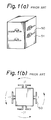
- Figs. 1(a) and 1(b) schematically illustrate a configuration of a horizontal polarized antenna apparatus which has an omnidirectional pattern in the horizontal plane explained in Chapter 12 of "VHF Antenna” written by Uchida and Mushiake, and issued by the Production Technology Center (March, 1977).
- Fig. 1(a) is a perspective view and Fig. 1(b) is a top plan view with electric field distribution indicated by arrows.
- the numeral 50 designates a dipole antenna and the symbol I indicates a current flowing through the dipole.
- a grounded conductor 51 includes four surfaces and a dipole antenna 50 is arranged at each surface.
- the dipole antenna 50 is arranged in parallel to the horizontal surface to excite a horizontally polarized wave.
- a plurality of dipole antennas may be arranged in the vertical direction. Amplitudes of currents flowing through the dipole antennas in the same height are equal, but phases thereof are sequentially different by 90 degrees.
- a dipole antenna 50 has a figure-of-8 type radiation directivity, but substantially horizontally polarized omnidirectivity can be obtained through a combination of the four dipole elements.
- Figs. 2(a) - 2(c) show a conventional slot antenna indicated in "X-band omnidirectional double-slot array antenna" by T. Takeshima, ELECTRONIC ENGINEERING, No. 39, pp. 617-621 (October, 1967).
- FIG. 2(a) is a perspective view
- Fig. 2(b) is a sectional view along the line A-A
- Fig. 2(c) is a side elevation.
- numeral 60 designates a radiation slot; 61 a waveguide; and 62 a flange.
- Fig. 3(a) is a diagram illustrating a distribution of magnetic field inside the waveguide 61.
- Fig. 3(b) is a cross-sectional view along the line A-A illustrating a distribution of magnetic field inside the waveguide and a current flowing along the side surface.
- Electromagnetic waves propagated along the rectangular waveguide 61 excite the radiation slots 60 to radiate electromagnetic waves if the radiation slots 60 are provided in parallel with the waveguide axis at the positions offset from the center of the H plane of the rectangular waveguide 61.
- the radiation slots 60 are excited by providing each of the radiation slots 60 at a position where the magnetic field inside the waveguide 61 becomes maximum.
- An amount of electromagnetic wave radiation can be adjusted by changing the position of each radiation slot 60.
- the waveguide slot antenna shown in Figs. 2(a) - 2(c) may be used as a horizontally polarized omnidirectional antenna
- the radiation slots 60 are provided, as shown in Fig. 4(a), on the front and rear H planes of the waveguide 61. Then, a distribution of electric field in the horizontal plane changes as shown in Fig. 4(b).
- the radiation slots 60 are excited out of phase and the radiation field becomes continuous in the horizontal plane. As a result, a theoretically omnidirectional directivity can be realized.
- two radiation slots can be excited in the same phase by arranging the radiation slots in symmetrical positions of the waveguide 61 with respect to the center thereof at an interval of ⁇ g/2 ( ⁇ g is a wavelength in the waveguide).
- Fig. 5 schematically illustrates a configuration of a transponder 70 provided with an antenna 71 shown in Fig. 2(a).
- This transponder 70 is provided with a transmitter/receiver (transceiver) 72 connected to the horizontally polarized antenna 71 which has an omnidirectional pattern in the horizontal plane.
- the transceiver 72 is activated by turning a switch 73 ON, getting the transceiver ready for receiving a signal.
- the transceiver 72 When the transceiver 72 under this condition receives a radar signal radiated from a searching plane, the transceiver 72 is switched to an electromagnetic wave radiation mode and transmits a response signal.
- the transceiver 72 is connected to a battery 74 and the transponder 70 is covered with a radome 75.
- An existing horizontally omnidirectional antenna structured such as explained above is widely used as an antenna apparatus for TV and radar.
- a waveguide slot antenna as shown in Fig. 2(a) is used, a substantially omnidirectional pattern can easily be achieved by providing radiation slots on the waveguide, but, if a ripple in the horizontal plane becomes large, any omnidirectional pattern cannot be obtained.
- a conventional transponder has the following problems in practical use. First, it is necessary to place the transponder in a waiting mode by turning ON the switch, but, in an emergency case, a user sometimes forgets to turn ON the power switch. In this case, the transponder does not function, thereby endangering a user's life.
- the transceiver which normally transmits a signal upon reception of a radar signal radiated from a searching plane, has no means for indicating which condition the apparatus is in. For example, it is unclear whether the transceiver is sometimes inoperative and does not perform transmission even when the switch is turned ON.
- US-A-4,922,259 discloses an antenna in which two patch antenna elements are disposed in parallel to respective ground planes and are excited in opposite circular polarizations.
- GB 2,221,577 discloses a blade antenna with a similar arrangement of elements.
- the present invention has been proposed to overcome the problems described above and it is therefore an object of the present invention to provide a small-sized horizontally polarized omnidirectional antenna having a simplified configuration.
- a transponder comprising an omnidirectional horizontally polarized antenna and capable of notifying an operator who has issued an emergency signal that the apparatus is activated and in a waiting mode, that the apparatus is then in a transmission mode and that a searching plane is coming closer.
- an antenna apparatus where radiation slots are arranged at opposite position on a grounded conductive hollow body and the radiation slots are excited out of phase to form an omnidirectional radiation pattern in a plane perpendicular to the hollow body.
- the hollow body is a rectangular hollow body formed of conductive plates and the slots are formed on the opposing the conductive plates and excited out of phase through a signal feeding line.
- the electrical field radiated from the radiation slots becomes continuous in a plane perpendicular to the hollow body, for instance, in the horizontal plane and therefore an omnidirectional radiation pattern can be obtained in the horizontal plane.
- the hollow body may be filled with a dielectric material whereby the antenna apparatus can be manufactured in a small size due to a wavelength shortening effect of the dielectric material.
- the signal feeding line and the radiation slots may be electromagnetically coupled with each other such that the radiation slots are excited out of phase with the signal feeding line.
- a plurality of radiation slots may be provided along the longitudinal axis of the hollow body.
- the radiation slots formed on the opposing conductive plates are excited out of phase and the radiation slots formed on the same conductive plate are excited in phase. Consequently, a beam width in a plane including the longitudinal axis can be narrowed and a gain can be increased.
- a difference in length of signal feeding lines used to feed the adjacent radiation slots on the same conductive plate can be set to integer times an operating wavelength or odd number of times a half of the operating wavelength.
- At least one conductive bar can be provided around the radiation slots to connect the opposing conductive plates, whereby any unwanted waveguide mode can be suppressed.
- the horn-type conductive plates enable a beam width in a plane including the longitudinal axis to be reduced without changing the size and position of the radiation slots and an omnidirectional high-gain radiation pattern to be achieved in the plane perpendicular to the longitudinal axis.
- Semi-cylindrical conductive plates may be provided to the conductive plates which have no radiation slots, whereby any influence of waves diffracted at the edges of the conductive plates can be avoided, an amount of ripple in the plane perpendicular to the longitudinal axis can be adjusted and an omnidirectional radiation pattern can be obtained without changing size and position of the slots.
- the signal feeding lines can be provided to the outer surfaces of dielectric layers formed on the opposing conductive plates.
- the hollow body can be a cylindrical hollow body having at least one radiation slot formed along the longitudinal axis of the cylindrical body and a conductive bar fixed inside the cylindrical body to one side edge of the radiation slot.
- the cylindrical body can be excited in the TE 01 mode, whereby the radiation slot can be excited without using the conductive bar and an omnidirectional radiation pattern can be obtained.
- the conductive cylindrical body can be provided with a center conductor.
- This center conductor can be a spiral conductor. Since a current flows through the outer conductor at a slanting angle with respect to the longitudinal axis of the cylindrical body, the radiation slots provided along the longitudinal axis can be excited and an omnidirectional radiation pattern can be obtained in a plane perpendicular to the longitudinal axis.
- Horn-type conductive plates can be provided on the respective surfaces perpendicular to the longitudinal axis of the conductive cylindrical body.
- the horn-type conductive plates enables a beam width in a plane including the longitudinal axis to be reduced without changing size and position of the radiation slots and a high gain omnidirectional radiation pattern to be obtained in the plane perpendicular to the longitudinal axis.
- the hollow body is a rectangular waveguide having radiation slots formed on the center line of the H planes of the rectangular waveguide and a member for disturbing a distribution of electromagnetic field inside the rectangular waveguide.
- the member can comprise conductive bars fixed to one side edge of a corresponding radiation slot or can be a dielectric material mounted at a position deviated from the center line of the rectangular waveguide.
- the conductive bars and the dielectric material operate to distribute an electromagnetic field in the rectangular waveguide a symmetrically with respect to the center line, whereby the radiation slots provided on the center line of the H planes are excited and an omnidirectional radiation pattern having no beam tilt can be obtained. Meanwhile, it is also possible to excite the rectangular waveguide in the TE 20 mode, in place of providing the above electromagnetic field disturbing member in the rectangular waveguide.
- the radiation slots provided on the centre line of the H planes can be excited out of phase and thereby an omnidirectional radiation pattern can be obtained in a plane perpendicular to the longitudinal axis of the rectangular waveguide.
- Fig. 1(a) is a perspective view of a conventional omnidirectional antenna apparatus.
- Fig. 1(b) is a plan view of the antenna apparatus of Fig. 1(a), illustrating a distribution of electric field.
- Fig. 2(a) is a perspective view illustrating another conventional omnidirectional antenna apparatus.
- Fig. 2(b) is a cross-sectional view taken along the line A-A of Fig. 2(a).
- Fig. 2(c) is a side elevation of the antenna apparatus of Fig. 2(a).
- Fig. 3(a) illustrates a distribution of magnetic field in the antenna apparatus of Fig. 2(a).
- Fig. 3(b) illustrates directions of current and magnetic field at the cross-section taken along the line A-A of Fig. 3(a).
- Fig. 4(a) is a diagram for explaining directivity of the antenna apparatus of Fig. 2(a).
- Fig. 4(b) illustrates a horizontal distribution of electric field established by the antenna apparatus of Fig. 4(a).
- Fig. 5 is a partially cutout diagram illustrating a conventional transponder.
- Fig. 6(a) is a perspective view of a first embodiment of an antenna apparatus of the present invention.
- Fig. 6(b) is a cross-sectional view taken along the line A-A of Fig. 6(a).
- Fig. 6(c) is a cross-sectional view taken along the line B-B of Fig. 6(a).
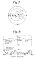
- Fig. 7 is a diagram for explaining operations of the antenna apparatus of Fig. 6(a).
- Fig. 8 is a graph illustrating a gain in the azimuth direction of the antenna apparatus of Fig. 6(a).
- Fig. 9(a) is a perspective view of a second embodiment of an antenna apparatus of the present invention.
- Fig. 9(b) is a cross-sectional view taken along the line A-A of Fig. 9(a).
- Fig. 9(c) is a cross-sectional view taken along the line B-B of Fig. 9(a).
- Fig. 10(a) is a perspective view of a third embodiment of an antenna apparatus of the present invention.
- Fig. 10(b) is a cross-sectional view taken along the like A-A of Fig. 10(a).
- Fig. 10(c) is a cross-sectional view taken along the line B-B of Fig. 10(a).
- Fig. 11(a) is a perspective view of a fourth embodiment of an antenna apparatus of the present invention.
- Fig. 11(b) is a cross-sectional view taken along the line A-A of Fig. 11(a).
- Fig. 11(c) is a cross-sectional view taken along the line B-B of Fig. 11(a).
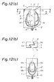
- Fig. 12(a) is a perspective view of a fifth embodiment of an antenna apparatus of the present invention.
- Fig. 12(b) is a cross-sectional view taken along the line A-A of Fig. 12(a).
- Fig. 12(c) is a cross-sectional view taken along the line B-B of Fig. 12(a).
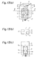
- Fig. 13(a) is a perspective view of a sixth embodiment of an antenna apparatus of the present invention.
- Fig. 13(b) is a cross-sectional view taken along the line A-A of Fig. 13(a).
- Fig. 13(c) is a cross-sectional view taken along the line B-B of Fig. 13(a).
- Fig. 14(a) is a perspective view of a seventh embodiment of an antenna apparatus of the present invention.
- Fig. 14(b) is a cross-sectional view taken along the line A-A of Fig. 14(a).
- Fig. 15(a) is a perspective view of an eighth embodiment of an antenna apparatus of the present invention.
- Fig. 15(b) is a side elevation of the antenna apparatus of Fig. 15(a).
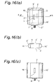
- Fig. 16(a) is a perspective view of a ninth embodiment of an antenna apparatus of the present invention.
- Fig. 16(b) is a cross-sectional view taken along the line A-A of Fig. 16(a).
- Fig. 16(c) is a side elevation of the antenna apparatus of Fig. 16(a).
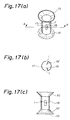
- Fig. 17(a) is a perspective view of a tenth embodiment of an antenna apparatus of the present invention.
- Fig. 17(b) is a cross-sectional view taken along the line A-A of Fig. 17(a).
- Fig. 17(c) is a side elevation of the antenna apparatus of Fig. 17(a).
- Fig. 18(a) is a perspective view of an eleventh embodiment of an antenna apparatus of the present invention.
- Fig. 18(b) is a cross-sectional view taken along the line A-A of Fig. 18(a).
- Fig. 18(c) is a side elevation of the antenna apparatus of Fig. 18(a).
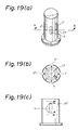
- Fig. 19(a) is a perspective view of a twelfth embodiment of an antenna apparatus of the present invention.
- Fig. 19(b) illustrates a distribution of electromagnetic field at the cross-section taken along the line A-A of Fig. 19(a).
- Fig. 19(c) illustrates a distribution of a current on the side surface of the antenna apparatus of Fig. 19(a).
- Fig. 20(a) is a perspective view of a thirteenth embodiment of an antenna apparatus of the present invention.
- Fig. 20(b) is a cross-sectional view taken along the line A-A of Fig. 20(a).
- Fig. 20(c) is a side elevation of the antenna apparatus of Fig. 20(a).
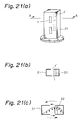
- Fig. 21(a) is a perspective view of a fourteenth embodiment of an antenna apparatus of the present invention.
- Fig. 21(b) is a cross-sectional view taken along the line A-A of Fig. 21(a).
- Fig. 21(c) illustrates a distribution of a current at the cross-section taken along the line A-A of Fig. 21(a).
- Fig. 22(a) is a perspective view of a fifteenth embodiment of an antenna apparatus of the present invention.
- Fig. 22(b) illustrates a distribution of electric field at the cross-section taken along the line A-A of Fig. 22(a).
- Fig. 23 is a perspective view of a sixteenth embodiment of an antenna apparatus of the present invention.
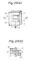
- Fig. 24(a) is a perspective view of a seventeenth embodiment of an antenna apparatus of the present invention.
- Fig. 24(b) is a cross-section taken along the line A-A of Fig. 24(a).
- Fig. 25(a) is a perspective view of an eighteenth embodiment of an antenna apparatus of the present invention.
- Fig. 25(b) is a cross-section taken along the line A-A of Fig. 25(a).
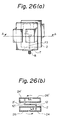
- Fig. 26(a) is a perspective view of a nineteenth embodiment of an antenna apparatus of the present invention.
- Fig. 26(b) is a cross-section taken along the line A-A of Fig. 26(a).
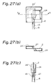
- Fig. 27(a) is a perspective view of a twentieth embodiment of an antenna apparatus of the present invention.
- Fig. 27(b) is a cross-sectional view taken along the line A-A of Fig. 27(a).
- Fig. 27(c) is a side elevation of the antenna apparatus of Fig. 27(a).
- Fig. 28 is a perspective view of a twenty-first embodiment of an antenna apparatus of the present invention.
- Fig. 29 is a perspective view of a transponder utilizing any one of the first to twentieth embodiments of the antenna apparatus of the present invention.
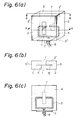
- Figs. 6(a) - 6(c) schematically illustrate a configuration of the first embodiment of the present invention, Fig. 6(a) being a perspective view, Fig. 6(b) cross-sectional view taken along the line A-A of Fig. 6(a) and Fig. 6(c) a cross-sectional view taken along the line B-B of Fig. 6(a).
- radiation slots 1, 1' are formed respectively on a first set of parallel conductive plates 2, 2' and both conductive plates 2, 2' are connected by a second set of conductive plates 3', 3", 3"' to configurate a rectangular parallelepiped.
- the inside of the rectangular parallelepiped is filled with a dielectric material 4.
- the radiation slots 1, 1' are excited by a triplate line 6 formed of the conductive plates 2, 2' and strip lines 5.
- Numeral 7 designates a coaxial connector for feeding the triplate line; and 8 a coaxial line.
- the conductive plates 2, 2', 3, 3', 3", 3"' are grounded.
- Fig. 7 is a diagram explaining the principle of the antenna apparatus of Fig. 6(a).
- a signal propagating through the coaxial line 8 enters the triplate line 6 via the coaxial connector 7.
- the triplate line 6 can be formed in a small size resulting in reduction in size of the antenna apparatus by filling the rectangular parallelepiped with the dielectric material 4.
- Both ends of the triplate line 6 are connected respectively to the right side edge of the radiation slot 1 and the left side edge of the slot 1' with respect to Fig. 6(b) and a voltage is applied across the strip line 5 and the first set of the ground conductive plates 2, 2'. Since the ends of the triplate line 6 are connected to the opposite side edges of the radiation slots 1, 1', the electric fields inside the rectangular parallelepiped formed of the first set of conductive plates 2, 2' and the second set of conductive plates 3', 3", 3′′′ are reversed with each other as indicated by the arrow marks in Fig. 7.
- the radiation slots 1, 1' provided on the grounded conductive plates 2, 2' are excited out of phase (in a phase difference of 180 degrees).
- the radiation field formed by these radiation slots 1, 1' becomes continuous in the horizontal plane (azimuth direction) and a horizontally polarized omnidirectional radiation pattern can be obtained.
- the radiation slots 1, 1' are fed with the triplate line 6, but another feeding line such as a coaxial line can also be used for the same purpose.
- Fig. 8 indicates measured gains of horizontally polarized and vertically polarized waves when the antenna apparatus of Fig. 6(a) is rotated 360 degrees in the horizontal plane.
- an amount of ripple is within 2 dB, resulting in a substantially omnidirectional pattern.
- the gain of the vertically polarized wave which is a cross-polarized wave is -20 dB or less and a satisfactory characteristics results.
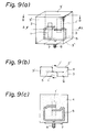
- Figs. 9(a) - 9(c) schematically illustrates a configuration of the second embodiment of the present invention, Fig .9(a) being perspective view, Fig. 9(b) a cross-sectional view taken along the line A-A and Fig. 9(c) a cross-sectional view taken along the line B-B.
- the second embodiment is different from the first embodiment in that both ends of the triplate line 6 are connected respectively to left side edge of the radiation slot 1 and the right side edge of the slot 1' with respect to Fig. 9(b).
- a voltage is applied across the radiation slots 1, 1' from the triplate line 6 for exciting the radiation slots 1, 1'.
- the radiation slots 1, 1' provided on the first set of grounded conductive plates 2, 2' are excited out of phase, a radiation field generated by these radiation slots 1, 1' becomes continuous in the horizontal plane (azimuth direction) and a horizontally polarized omnidirectional radiation pattern can be obtained.
- the ends of the triplate line 6 are connected to the radiation slots 1, 1', but a similar characteristic can also be obtained by open-circuiting the ends of the triplate line and setting the length between the open-circuited ends and the radiation slots 1, 1' to approximately a quarter of the wavelength of an operating frequency.
- Figs. 10(a) - 10(c) schematically illustrate a configuration of the third embodiment of the present invention, Fig. 10(a) being a perspective view, Fig. 10(b) a cross-sectional view taken along the line A-A and Fig. 10(c) a cross-sectional view taken along the line B-B.
- This embodiment is different from the first embodiment in that a portion 9 of the dielectric material 4 corresponding to the radiation slots 1, 1' is removed.
- the antenna apparatus of this embodiment also shows, with the same principle as the antenna apparatus of the embodiment 1, a horizontally polarized omnidirectional radiation pattern.
- the radiation slots 1, 1' of the third embodiment must be longer, in order to have them resonate at the same resonance frequency than those of the first embodiment wherein no dielectric material 4 is removed, because a wavelength shortening effect by the dielectric material 4 is lost.
- the radiation slots 1, 1' being set longer, the beam width becomes narrow, the gain in the direction perpendicular to the plates 2, 2' increases and the gain in the horizontal plane can be increased. It is noted that a dielectric material may be provided in a parallelepiped defined by the radiation slots 1, 1'.
- Figs. 11(a) - 11(c) schematically illustrate a configuration of the fourth embodiment of the present invention, Fig. 11(a) being a perspective view, Fig. 11(b) a cross-sectional view taken along the line A-A and Fig. 11(c) a side elevation.
- the strip lines 5, 5' are provided on second dielectric materials 11, 11' formed on the conductive plates 2, 2' so that microstrip lines 10, 10' are configurated by the first set of conductive plates 2, 2' and the strip conductors 5 and 5'.
- Ends of the microstrip lines 10 and 10' are open-circuited. At the ends the electric field is maximum, while the magnetic field is minimum. Since the magnetic field becomes maximum at a position separated a quarter of the wavelength from the ends of the microstrip lines, the radiation slots 1, 1' are electromagnetically coupled with the microstrip lines 10, 10' by providing such radiation slots 1, 1' at the position described above.
- the radiation slots 1, 1' provided on the first set of conductive plates 2, 2' are excited by the microstrip lines 10, 10' out of phase, the radiation field produced by the radiation slots 1, 1' becomes continuous in the horizontal plane (azimuth direction) and a horizontally polarized omnidirectional radiation pattern can be obtained.
- the ends of the microstrip lines 10, 10' are open-circuited to excite the radiation slots 1, 1', but the end of each microstrip line 10, 10' can be connected to a side edge of one of the radiation slots 1, 1' using, for instance, a through hole.
- the dielectric material 4 filling the rectangular parallelepiped surrounded by the first and second sets of conductive plates can be replaced with air.
- Figs. 12(a) - 12(c) schematically illustrate a configuration of the fifth embodiment of the present invention, Fig. 12(a) being a perspective view, Fig. 12(b) a cross-sectional view taken along the line A-A and Fig. 12(c) a side elevation.
- a center conductor 13 of the signal feeding connector 7 is divided into two conductors 12, 12' which are divided respectively into two conductors 12a, 12b; 12c, 12d.
- the conductors 12a, 12b are each connected to a side edge of a corresponding one of the radiation slots 1, 1' provided in a vertical arrangement on the grounded conductive plate 2, while the other conductors 12c, 12d are each connected to a side edge of a corresponding one of the radiation slots 1, 1' provided in a vertical arrangement on the grounded conductive plate 2'.
- a difference in length of the signal feeding lines for the adjacent radiation slots 1, 1; 1', 1' formed on the same conductive plate is an integer times the operation wavelength. Therefore, the adjacent radiation slots 1, 1 on the grounded conductive plate 2 are excited in the same phase while the radiation slots 1', 1' on the other grounded conductive plate 2' are excited out of phase.
- the electromagnetic waves radiated from the radiation slots formed on the same grounded conductive plate are in the same phase in the horizontal plane, resulting in increase in gain in the horizontal plane.
- the radiation slots 1, 1 on the conductive plate 2 are excited out of phase with respect to the radiation slots 1', 1' on the conductive plate 2', the radiation field produced by these radiation slots 1, 1; 1', 1' become continuous in the horizontal plane and a horizontally polarized omnidirectional high-gain radiation pattern can be obtained in the horizonal plane.
- the beam width in the vertical plane can be adjusted by changing an interval between the vertically arranged radiation slots on the same conductive plate.
- the number of radiation slots formed on the same conductive plate is not limited to two and three or more radiation slots can be provided.
- the signal feeding line may be replaced with other lines such as a coaxial line.
- Figs. 13(a) - 13(c) schematically illustrate a configuration of the sixth embodiment of the present invention, Fig. 13(a) being a plan view, Fig. 13(b) a cross-sectional view taken along the line A-A and Fig. 13(c) a cross-sectional view taken along the line B-B.
- the center conductor 13 of the signal feeding connector 7 is divided into and connected to the strip lines 5, 5'.
- These strip lines 5, 5' are then divided into two strip lines 5a, 5b; 5c, 5d.
- the strip lines 5a, 5d are connected to different side edges of the radiation slots 1, 1' provided on the conductive plate 2', while the other strip lines 5b, 5c are connected to the different side edges of the radiation slots 1, 1' provided on the conductive plate 2.
- a difference in length of the signal lines for the radiation slots formed on the same conductive plate is set to an odd number times a half of the wavelength. Therefore, the radiation slots 1, 1' on one conductive plate 2 are excited in the same phase, while the radiation slots on the other conductive plate are excited out of phase.
- the beam width in the vertical plane can be adjusted by changing an interval of the vertically arranged radiation slots on the same conductive plate.
- the number of radiation slots formed on the same conductive plate is not limited to two and three or more radiation slots can be provided.
- the signal feeding line may be replaced with other lines such as a coaxial line.
- Figs. 14(a) - 14(b) schematically illustrate a configuration of the seventh embodiment of the present invention, Fig. 14(a) being a perspective view and Fig. 14(b) a cross-sectional view taken along the line A-A.
- This embodiment is different from the fifth embodiment in that a plurality of pins 14 for connecting the first set of grounded conductive plates 2, 2' are provided in the antenna.
- the periphery of the radiation slots 1, 1' is surrounded by the conductive plates 2, 2' and this configuration can be considered as a waveguide and a waveguide mode can be excited therein. If the width of the conductive plates 2, 2' is determined to be a half of the wavelength or less, only the basic mode is propagated if no connecting pin 14 is provided in the waveguide.
- the radiation slots 1, 1, 1', 1' formed along the center of the conductive plates 2, 2' are inherently not excited, but these radiation slots are actually excited because the internal electromagnetic field is disturbed due to the existence of the internal feeding lines 12, 12'.
- any unwanted waveguide mode is suppressed by the pins 14 connecting the conductive plates 2, 2', thereby obtaining an omnidirectional radiation pattern.
- the pins 14 are used for suppressing unwanted mode, but conductive bars or plates can be used in place of the pins 14.
- Figs. 15(a) and 15(b) schematically illustrate a configuration of the eighth embodiment of the present invention, Fig. 15(a) being a perspective view and Fig. 15(b) a side elevation.
- horn-type metal conductors 15, 15' are coupled to upper and lower surfaces of the antenna apparatus of the first - seventh embodiments.
- this embodiment employs the horn-type conductors 15, 15' coupled to the upper and lower ends of the antenna apparatus described in the foregoing embodiments.
- the horn-type conductors 15, 15' operate in combination like a horn antenna. Since the gain of this antenna is determined by a size of the aperture of the horn, a higher gain can be obtained by enlarging the aperture of the horn.
- the beam width and gain in the vertical plane can be easily adjusted by changing the slant angle ⁇ .
- Figs. 16(a) - 16(c) schematically illustrate a configuration of the ninth embodiment of the present invention, Fig. 16(a) being a perspective view, Fig. 16(b) a cross section taken along the line A-A and Fig. 16(c) a side elevation.
- This embodiment provides a third set of conductive plates 16, 16' that electrically connect the first set of conductive plates 2, 2' of the antenna apparatus of the first embodiment.
- an omnidirectional radiation pattern can be obtained if a size of the conductive plates 2, 2' is infinite. Since the conductive plates 2, 2' are limited in size, however, a ripple is generated due to the interference of waves diffracted at the edge portions of the conductive plates 2, 2'. The generated ripple changes in the period of about one wavelength depending on the size of the conductive plates 2, 2'.
- the conductive plates 16, 16' are additionally provided to cover the opposing conductive plates 3, 3" of the antenna apparatus according to the first to seventh embodiments.
- the third set of conductive plates 16, 16' though shown in Fig. 16(b) to have a semi-circular cross-section in order to change the size of the conductive plates 2, 2', can be formed to have an elliptic or rectangular cross-section. Whether the spaces between the conductive plates 3, 3" and the third set of conductive plates 16, 16' are filled with a dielectric material or not is optional.
- Figs. 17(a) - 17(c) schematically illustrate a configuration of the tenth embodiment of the present invention, Fig. 17(a) being a perspective view, Fig. 17(b) a cross section taken along the line A-A and Fig. 17(c) a side elevation.
- the radiation slots 1, 1' are formed to oppose each other on a cylindrical waveguide 17 of which both ends are short-circuited. To one side edge of each of the radiation slots 1, 1' are soldered conductive bars 18, 18'. Numeral 19 designates a waveguide flange.
- a current flows in the axial direction. If the radiation slots 1, 1' are provided in parallel to the axis of the waveguide 17, the radiation slots 1, 1' are not excited because the slots do not cross the current.
- the radiation slots 1, 1' can be excited by fixing the conductive bars 18, 18' inside the circular waveguide 17 from the side edges of the radiation slots 1, 1'.
- a horizontally polarized omnidirectional radiation pattern can be obtained by arranging one or more radiation slots in the circumferential direction of the cylindrical waveguide 17.
- the beam width in the vertical plane can be narrowed by arranging a plurality of radiation slots in parallel to the longitudinal axis of the circular waveguide 17.
- the radiation slots 1, 1' are excited by exciting the cylindrical conductor 17, a standing wave position deviates when an excitation frequency of the waveguide 17 changes. Then, the amplitude and phase of a signal exciting the radiation slots 1, 1' change and a radiation pattern obtained by combining radiation fields from the slots 1, 1' also changes. It is possible to provide the horn-type conductors 15, 15' as in the case of the eighth embodiment, to both ends of the circular waveguide 17 in order to obtain a narrower beam width in the vertical plane.
- the radiation slots 1, 1' are excited using the conductor bars 18, 18', but it is possible to excite the radiation slots 1, 1' by slanting the radiation slots 1, 1' with respect to the axis of the circular waveguide 17.
- Figs. 18(a) - 18(c) schematically illustrate a configuration of the eleventh embodiment of the present invention, Fig. 18(a) being a perspective view, Fig. 18(b) a plan view taken along the line A-A and Fig. 18(c) a side elevation.
- a center conductor 20 is provided through the circular waveguide 17 of the tenth embodiment to form a coaxial line 17'. If the coaxial line 17' including short-circuited ends is excited in the basic mode (the magnetic field is uniform in the circumferential direction of the coaxial line 17'), a current flows in the longitudinal axial direction. If the radiation slots 1, 1' are provided in parallel to the axis of the coaxial line 17', the radiation slots 1, 1' are not excited.
- a horizontally polarized omnidirectional radiation pattern can be obtained by providing one or more radiation slots in the circumferential direction.
- a plurality of radiation slots may be arranged in parallel to the axis of the coaxial line 17'. Since the radiation slots 1, 1' are excited by exciting the coaxial line 17' the position of a standing wave is deviated if the excitation frequency of the coaxial line 17' is shifted. Then, the amplitude and phase of a signal for exciting the radiation slots 1, 1' change and a radiation pattern obtained by combining the radiation fields from the slots 1, 1' is also changed.
- the horn-type conductors 15, 15' may be provided, as in the case of the eighth embodiment, to both ends of the coaxial line 17' in view of obtaining a narrower beam width in the vertical direction.
- Figs. 19(a) - 19(c) schematically illustrate a configuration of the twelfth embodiment of the present invention
- Fig. 19(a) being a perspective view
- Fig. 19(b) showing a distribution of electromagnetic wave at the cross-section taken along the line A-A
- Fig. 19(c) showing a distribution of current on the side surface.
- the cylindrical waveguide 17 is excited in the TE 01 mode and the radiation slots 1, 1', 1", 1′′′ are formed in the axial direction the cylindrical waveguide 17.
- a current flows in the circumferential direction of the cylindrical waveguide 17 as shown in Fig. 19(c). Therefore, the radiation slots can easily be excited by providing the slots in parallel to the longitudinal axis of the waveguide.
- a horizontally polarized omnidirection radiation pattern can be obtained by arranging one or more slots in the circumferential direction.
- a beam width in the vertical direction can be narrowed by arranging a plurality of radiation slots in the longitudinal axial direction of the waveguide 17 or providing horn-type conductors at both ends of the circular waveguide 17.
- Figs. 20(a) - 20(c) schematically illustrate a configuration of the thirteenth embodiment of the present invention, Fig. 20(a) being a perspective view, Fig. 20(b) a cross-sectional view taken along the line A-A and Fig. 20(c) a side elevation.
- the radiation slots 1, 1' are formed on two opposing surfaces of a rectangular waveguide 21. If the rectangular waveguide 21 having short-circuited ends is excited in the TE 10 mode, the radiation slots 1, 1' must be formed at positions offset from the longitudinal axis of the waveguide 21 for excitation. Then, a beam tilt is generated like in the prior art and a ripple in the horizontal plane becomes large.
- the radiation slots 1, 1' are provided in parallel with the center line of the H plane of the rectangular waveguide 21 and the conductive bars 18, 18' protruding inside the waveguide 21 are fixed to the side edges of the radiation slots 1, 1'.
- the conductive bars 18, 18' establish a distribution of electromagnetic field asymmetrical with respect to the center line of the rectangular waveguide 21, whereby the radiation slots 1, 1' provided on the center line of the plane H are excited, resulting in the generation of an omnidirectional radiation pattern having no beam tilt.
- Figs. 21(a) - 21(c) schematically illustrate a configuration of the fourteenth embodiment of the present invention, Fig. 21(a) being a perspective view, Fig. 21(b) a cross-sectional view taken along the line A-A and Fig. 21(c) showing a distribution of electric field at the cross-section taken along the line A-A.
- a dielectric material 22 is fixed inside the rectangular waveguide 21 in place of the conductive bars 18, 18' used in the thirteenth embodiment.
- the radiation slots 1, 1' must be formed at positions offset from the center of the waveguide 21 for the excitation. Then, a beam tilt is generated like in the prior arts and a ripple in the horizontal plane becomes large.
- the dielectric material 22 is provided at the position offset from the center of the rectangular waveguide 21, whereby the radiation slots 1, 1' are excited as a result of a change in distribution of the electromagnetic field inside the rectangular waveguide 21 as shown in Fig. 21(c). Since the conductive bars 18, 18' are not used in this embodiment, such a process as soldering is advantageously unnecessary.
- Figs. 22(a) and 22(b) schematically illustrate a configuration of the fifteenth embodiment of the present invention, Fig. 22(a) being a perspective view and Fig. 22(b) showing a distribution of electric field at a cross-section taken along the line A-A.
- the rectangular waveguide 21 is excited in the TE 20 mode and the ends of the rectangular waveguide 21 are short-circuited.
- the electromagnetic field inside the rectangular waveguide 21 becomes zero at the center of the H plane as shown in Fig. 22(b), whereby the radiation slots 1, 1' can be excited out of phase.
- the radiation field from the radiation slots 1, 1' becomes continuous in the horizontal plane and a horizontally polarized omnidirectional radiation pattern can be obtained.
- Fig. 23 schematically illustrates a configuration of the sixteenth embodiment of the present invention.
- the radiation slots 1, 1', 1", 1′′′ formed on the outer conductor of the coaxial line 17' are excited by a spiral inner conductor 23.
- the coaxial line 17' the ends of which are short-circuited, is excited in the basic mode (the magnetic field is uniform in the circumferential direction of the coaxial line 17'), a current flows in the longitudinal axial direction. If the radiation slots 1, 1', 1", 1′′′ are provided in parallel to the longitudinal axis of the line 17', the radiation slots are not excited.
- the spiral inner conductor 23 is used in place of the conductive bars 18, 18' used in the thirteenth embodiment and the dielectric material 22 used in the fourteenth embodiment.
- the spiral inner conductor 23 enables a current to flow through the outer conductor slantly with respect to the longitudinal axis, and the radiation slots 1, 1', 1", 1′′′ provided in parallel to the longitudinal axis can be excited.
- a horizontal polarization omnidirectional radiation pattern can be obtained by arranging one or more radiation slots in the circumferential direction of the coaxial line 17'.
- a plurality of radiation slots may be arranged in the longitudinal axial direction of the coaxial line 17' or horn-type conductors can be provided as explained in the eleventh embodiment.
- the whole part or a part of the inner conductor 23 may be formed in spiral and the end of the inner conductor 23 may be open-or short-circuited.
- Figs. 24(a) and 24(b) schematically illustrate a configuration of the seventeenth embodiment of the present invention, Fig. 24(a) being a perspective view and Fig. 24(b) showing a cross-sectional view taken along the line A-A and a distribution of electric field thereat.
- Fig. 24(a) being a perspective view
- Fig. 24(b) showing a cross-sectional view taken along the line A-A and a distribution of electric field thereat.
- one side edge of each of patch conductors 24, 24' is short-circuited to a corresponding edge of the conductive plate 2, 2' to form a microstrip antenna.
- the microstrip antenna according to the present embodiment can be formed by dividing the ordinary microstrip antenna into two sections with a short-circuiting conductor and using one of the two sections as an antenna. A wave polarized perpendicularly to the short-circuiting conductor is generated as in the microstrip antenna by feeding the antenna at a position perpendicular to the short-circuiting conductor.
- a pair of microstrip antennas of the same shape having the patch conductors 24, 24' are arranged in such a manner that the conductive plates 2, 2' are parallel with each other, that both microstrip antennas face in opposite directions, and that the two patch conductors 24, 24' are fed out of phase.
- the produced radiation field becomes continuous in the horizontal plane (azimuth direction) and an omnidirectional radiation pattern can be obtained.
- Figs. 25(a) and 25(b) schematically illustrate a configuration of the eighteenth embodiment of the present invention, Fig. 25(a) being a perspective view of and Fig. 25(b) showing a distribution of electric field in a cross-sectional view taken along the line A-A.
- the grounded conductive plate 2 is formed to have a figure-S type and excited with the coaxial lines 8', 8" which are divided from the coaxial line 8 through a divider 25.
- the earth conductive plate is folded at both end portions in opposite directions and the folded portions are then further folded at both end portions.
- the further folded portions form patch conductors of each of which one side edge is short-circuited. These patch conductors are fed out of phase with the coaxial line 8', 8".
- the radiation field becomes continuous in the horizontal plane (azimuth direction) and an omnidirectional radiation pattern can be obtained by feeding the two patch conductors out of phase as in the seventeenth embodiment.
- Figs. 26(a) and 26(b) schematically illustrate a configuration of the nineteenth embodiment of the present invention, Fig. 26(a) being a perspective view and Fig. 26(b) showing a distribution of electric field in a cross-section taken along the line A-A.
- This embodiment provides a configuration that non-excited second patch conductors 26, 26' are added to the antenna apparatus of the seventeenth embodiment and one side edge of each of the patch conductors 26, 26' is short-circuited to a corresponding one of the conductive plates 2, 2'.
- the antenna apparatus shown in Fig. 26(a) can provide an omnidirectional radiation pattern as in the seventeenth and eighteenth embodiments.
- a pair of microstrip antennas of the same shape having the patch conductors 24, 24', 26, 26' are arranged in such a manner that the grounded conductive plates 2, 2' are disposed in parallel with each other, that both of the microstrip antennas face in opposite directions, and that the patch conductors 24, 24' are fed out of phase with respect to each other.
- the non-excited patch conductors 26, 26' are provided on the grounded conductive plates 2, 2' so as to face corresponding patch conductors 24, 24' to form a symmetrical antenna apparatus.
- the radiation field becomes continuous in the horizontal plane (azimuth direction) by exciting the two microstrip antennas out of phase. Since the antenna apparatus of the seventeenth embodiment has an asymmetrical configuration as shown in Fig. 24(b), ripples appear in the horizontal plane. In order to make the antenna apparatus bisymmetrical, the second patch conductors 26, 26' of the same shape are provided as shown in Fig. 26(b). The thus structured antenna apparatus has a symmetrical configuration and can improve a directivity in the horizontal plane.
- Figs. 27(a) - 27(c) schematically illustrate a configuration of the twentieth embodiment of the present invention, Fig. 27(a) being a perspective view, Fig. 27(b) a cross-sectional view taken along the line A-A and Fig. 27(c) a side elevation.
- the patch conductors 24, 24' are provided on both surfaces of the conductive plate 2, and the inner conductor 13 of the coaxial line 8 is connected to the conductive plate 2, while an outer conductor 27 of the coaxial line 8 to the patch conductors 24, 24'.
- the inner conductor 13 of the coaxial feeding line 8 must be divided into two sections, resulting in a complicated configuration.
- the outer conductor 27 of the coaxial line 8 is divided into two sections, the radiating conductors (patch conductors 24, 24') are excited and the inner conductor 13 is connected to the conductive plate 2.
- the thus configured antenna apparatus operates in the same manner as in the case where the inner conductor 13 is divided into two sections, and the feeding circuit may be simplified.
- Fig. 28 schematically illustrates a configuration of the twenty-first embodiment of the present invention.
- a radome 28 has radiation slots 29, 29', 29", ... and accommodates any one of the omnidirectional antennas 30 described in the foregoing embodiments.
- the radiation pattern is influenced to a certain degree by the radome even if the radome is transparent to an electromagnetic wave.
- this embodiment employs the radome 28 comprising a cylindrical cover of a dielectric material and a conductive film formed on the inner surface of the cylindrical cover, radiation slots 29, 29', 29", ... being formed on the conductive film in order to reradiate the electromagnetic wave to obtain an omnidirectional radiation pattern. Since a plurality of radiation slots are provided in the circumferential direction of the radome 28, an omnidirectional radiation pattern can be obtained without any influence given by the radome 28.
- a plurality of radiation slots may be arranged along the longitudinal axis of the radome 28 and dipole antennas may be used in place of the slots.
- Fig. 29 schematically illustrates a configuration of a transponder comprising a transceiver, any one of the omnidirectional antenna apparatus 30 according to the present invention described heretofore, a transceiver 33, a battery 34 and the radome 28.
- the transponder comprises a switch 35, an indicator 36 for indicating that the transceiver 33 is waiting for a signal received, an indicator 37 for indicating that the transceiver 33 is transmitting a signal and an indicator 38 for indicating a level of received signal.
- the transponder can improve a man-machine relation within a limit of a predetermined volume and weight by utilizing the omnidirectional antenna which is designed smaller than a conventional waveguide slot antenna.
- the transponder of this embodiment makes particular contribution to the improvement in relation between an operator and the machine when emergent signal transmission is required.
- the transponder is provided with the indicator 35 as a means for informing that the transceiver 33 can receive a signal and transmit a response, that is, that the transceiver has been activated and is waiting for reception of a signal.
- the transponder is provided with the indicator 37 as a means for informing an operator that the transceiver has been activated and is transmitting a signal, whereby the operator can confirm that the transponder is correctly operating.
- the transponder is provided with the indicator 38 as a means for enabling an operator to monitor a level of received signal, thereby confirming whether or not a searching plane is coming closer.
Landscapes
- Waveguide Aerials (AREA)
- Variable-Direction Aerials And Aerial Arrays (AREA)
- Details Of Aerials (AREA)
Priority Applications (1)
| Application Number | Priority Date | Filing Date | Title |
|---|---|---|---|
| EP01104794A EP1115175B1 (fr) | 1994-05-20 | 1994-11-16 | Antenne à fente omnidirectionelle |
Applications Claiming Priority (4)
| Application Number | Priority Date | Filing Date | Title |
|---|---|---|---|
| JP10716694A JP3176217B2 (ja) | 1993-05-21 | 1994-05-20 | アンテナ装置 |
| JP10716694 | 1994-05-20 | ||
| JP107166/94 | 1994-05-20 | ||
| EP94308457A EP0683542B1 (fr) | 1994-05-20 | 1994-11-16 | Antenne à fente omnidirectionelle |
Related Parent Applications (1)
| Application Number | Title | Priority Date | Filing Date |
|---|---|---|---|
| EP94308457A Division EP0683542B1 (fr) | 1994-05-20 | 1994-11-16 | Antenne à fente omnidirectionelle |
Related Child Applications (1)
| Application Number | Title | Priority Date | Filing Date |
|---|---|---|---|
| EP01104794A Division EP1115175B1 (fr) | 1994-05-20 | 1994-11-16 | Antenne à fente omnidirectionelle |
Publications (2)
| Publication Number | Publication Date |
|---|---|
| EP0891004A1 true EP0891004A1 (fr) | 1999-01-13 |
| EP0891004B1 EP0891004B1 (fr) | 2002-05-29 |
Family
ID=14452166
Family Applications (3)
| Application Number | Title | Priority Date | Filing Date |
|---|---|---|---|
| EP94308457A Expired - Lifetime EP0683542B1 (fr) | 1994-05-20 | 1994-11-16 | Antenne à fente omnidirectionelle |
| EP01104794A Expired - Lifetime EP1115175B1 (fr) | 1994-05-20 | 1994-11-16 | Antenne à fente omnidirectionelle |
| EP98116906A Expired - Lifetime EP0891004B1 (fr) | 1994-05-20 | 1994-11-16 | Antenne à fente omnidirectionelle |
Family Applications Before (2)
| Application Number | Title | Priority Date | Filing Date |
|---|---|---|---|
| EP94308457A Expired - Lifetime EP0683542B1 (fr) | 1994-05-20 | 1994-11-16 | Antenne à fente omnidirectionelle |
| EP01104794A Expired - Lifetime EP1115175B1 (fr) | 1994-05-20 | 1994-11-16 | Antenne à fente omnidirectionelle |
Country Status (3)
| Country | Link |
|---|---|
| US (1) | US5717410A (fr) |
| EP (3) | EP0683542B1 (fr) |
| NO (5) | NO316144B1 (fr) |
Cited By (1)
| Publication number | Priority date | Publication date | Assignee | Title |
|---|---|---|---|---|
| EP2424043A1 (fr) * | 2010-08-25 | 2012-02-29 | Advanced Connection Technology, Inc. | Structure d'antenne |
Families Citing this family (23)
| Publication number | Priority date | Publication date | Assignee | Title |
|---|---|---|---|---|
| US5900843A (en) * | 1997-03-18 | 1999-05-04 | Raytheon Company | Airborne VHF antennas |
| US6078271A (en) * | 1998-02-20 | 2000-06-20 | Lear Automotive Dearborn, Inc. | Multiple-frequency programmable transmitter |
| US6308083B2 (en) | 1998-06-16 | 2001-10-23 | Lear Automotive Dearborn, Inc. | Integrated cellular telephone with programmable transmitter |
| US6175337B1 (en) * | 1999-09-17 | 2001-01-16 | The United States Of America As Represented By The Secretary Of The Army | High-gain, dielectric loaded, slotted waveguide antenna |
| US20040110481A1 (en) * | 2002-12-07 | 2004-06-10 | Umesh Navsariwala | Antenna and wireless device utilizing the antenna |
| CN1886752B (zh) * | 2003-11-04 | 2011-09-07 | 艾利丹尼森公司 | 具有加强读出能力的射频识别标签 |
| WO2007004340A1 (fr) * | 2005-06-30 | 2007-01-11 | Yagi Antenna Inc. | Antenne |
| WO2007055113A1 (fr) * | 2005-11-10 | 2007-05-18 | Matsushita Electric Industrial Co., Ltd. | Fente rayonnante |
| US7342500B2 (en) * | 2006-03-24 | 2008-03-11 | Mark Iv Industries, Corp. | Compact microstrip transponder antenna |
| JP4904196B2 (ja) * | 2007-05-08 | 2012-03-28 | パナソニック株式会社 | 不平衡給電広帯域スロットアンテナ |
| EP2226652B1 (fr) | 2009-03-02 | 2013-11-20 | Sick Ag | Capteur optoélectronique doté d'un émetteur à lampe d'orientation |
| EP2226655B1 (fr) | 2009-03-02 | 2012-05-16 | Sick Ag | Capteur optoélectronique |
| US8779998B1 (en) | 2010-09-21 | 2014-07-15 | The United States Of America, As Represented By The Secretary Of The Navy | Wideband horizontally polarized omnidirectional antenna |
| JP5310707B2 (ja) | 2010-12-15 | 2013-10-09 | 横河電機株式会社 | 耐圧防爆容器 |
| WO2011157172A2 (fr) * | 2011-06-03 | 2011-12-22 | 华为技术有限公司 | Antenne omni-directionnelle |
| DE102012000762A1 (de) * | 2012-01-18 | 2013-07-18 | Ott-Jakob Spanntechnik Gmbh | Antennenabdeckung |
| US10530061B2 (en) * | 2015-08-05 | 2020-01-07 | Hewlett-Packard Development Company, L.P. | Mixed mode slot antennas |
| WO2017047381A1 (fr) * | 2015-09-18 | 2017-03-23 | Ntn株式会社 | Antenne à fentes en guide d'ondes et son procédé de fabrication |
| FR3054940B1 (fr) * | 2016-08-04 | 2019-08-09 | Peugeot Citroen Automobiles Sa | Dispositif d'emission et/ou de reception radioelectrique a ouvertures independantes |
| WO2018077952A1 (fr) * | 2016-10-25 | 2018-05-03 | Filtronic Wireless Ab | Agencement comprenant des éléments d'antenne |
| US10242577B2 (en) * | 2016-12-01 | 2019-03-26 | Honeywell International Inc. | Data communication between airport surveillance radar and onboard airborne weather radar |
| AU2017272234B2 (en) | 2016-12-20 | 2021-12-02 | Licensys Australasia Pty Ltd | An antenna |
| CN110429382B (zh) * | 2019-08-05 | 2021-01-19 | 铜陵市华东玻璃钢工业有限责任公司 | 复合型天线罩及其制备方法 |
Citations (5)
| Publication number | Priority date | Publication date | Assignee | Title |
|---|---|---|---|---|
| US3969730A (en) * | 1975-02-12 | 1976-07-13 | The United States Of America As Represented By The Secretary Of Transportation | Cross slot omnidirectional antenna |
| US4247858A (en) * | 1979-05-21 | 1981-01-27 | Kurt Eichweber | Antennas for use with optical and high-frequency radiation |
| JPS58181303A (ja) * | 1982-04-09 | 1983-10-24 | Oki Electric Ind Co Ltd | 無指向性アンテナ |
| US4451830A (en) * | 1980-12-17 | 1984-05-29 | The Commonwealth Of Australia | VHF Omni-range navigation system antenna |
| US4590479A (en) * | 1984-03-29 | 1986-05-20 | Rca Corporation | Broadcast antenna system with high power aural/visual self-diplexing capability |
Family Cites Families (24)
| Publication number | Priority date | Publication date | Assignee | Title |
|---|---|---|---|---|
| US2660674A (en) * | 1948-10-14 | 1953-11-24 | Rca Corp | Slotted antenna system |
| US2771605A (en) * | 1954-10-11 | 1956-11-20 | Cook Electric Co | Omnidirectional antenna |
| US2785399A (en) * | 1955-11-30 | 1957-03-12 | Edward F Harris | High frequency antenna |
| US2818565A (en) * | 1956-09-05 | 1957-12-31 | James S Ajioka | Slab excited continuous slot antenna |
| US3680130A (en) * | 1969-11-12 | 1972-07-25 | Us Army | Re-entry vehicle nose cone with antenna |
| US3656166A (en) * | 1970-06-05 | 1972-04-11 | American Electronic Lab | Broadband circularly polarized omnidirectional antenna |
| US3757290A (en) * | 1971-03-12 | 1973-09-04 | Sperry Rand Corp | Automatic vehicle monitoring system |
| US3829863A (en) * | 1973-03-12 | 1974-08-13 | Gen Instrument Corp | Polarizing feed apparatus for biconical antennas |
| FR2372522A1 (fr) * | 1976-11-30 | 1978-06-23 | Thomson Csf | Antenne omnidirectionnelle a diagramme de directivite reglable en site |
| GB2067842B (en) * | 1980-01-16 | 1983-08-24 | Secr Defence | Microstrip antenna |
| DE3023562C2 (de) * | 1980-06-24 | 1982-10-28 | Siemens AG, 1000 Berlin und 8000 München | Einrichtung zur Polarisationsumwandlung elektromagnetischer Wellen |
| US4388388A (en) * | 1981-06-04 | 1983-06-14 | General Dynamics Electronics Division | Method of forming metallic patterns on curved surfaces |
| JPS58151705A (ja) * | 1982-03-05 | 1983-09-09 | Mitsubishi Electric Corp | 導波管形スロツトアレイアンテナ |
| JPS5955603A (ja) * | 1982-09-24 | 1984-03-30 | Nissan Motor Co Ltd | エツジスロツトアンテナ |
| GB2142475A (en) * | 1983-06-29 | 1985-01-16 | Decca Ltd | Wide beam microwave antenna |
| JPS60180205A (ja) * | 1984-02-27 | 1985-09-14 | Mitsubishi Electric Corp | 導波管スロツトアレ−アンテナ |
| US4763130A (en) * | 1987-05-11 | 1988-08-09 | General Instrument Corporation | Probe-fed slot antenna with coupling ring |
| JPH01143506A (ja) * | 1987-11-30 | 1989-06-06 | Sony Corp | 平面アンテナ |
| US4922259A (en) * | 1988-02-04 | 1990-05-01 | Mcdonnell Douglas Corporation | Microstrip patch antenna with omni-directional radiation pattern |
| GB2221577B (en) * | 1988-08-05 | 1991-11-20 | Marconi Co Ltd | Blade antenna |
| US5103241A (en) * | 1989-07-28 | 1992-04-07 | Hughes Aircraft Company | High Q bandpass structure for the selective transmission and reflection of high frequency radio signals |
| FR2655778B1 (fr) * | 1989-12-08 | 1993-12-03 | Thomson Csf | Antenne iff aeroportee a diagrammes multiples commutables. |
| US5134420A (en) * | 1990-05-07 | 1992-07-28 | Hughes Aircraft Company | Bicone antenna with hemispherical beam |
| JPH06140829A (ja) * | 1992-10-26 | 1994-05-20 | Nippon Telegr & Teleph Corp <Ntt> | マイクロストリップアンテナ |
-
1994
- 1994-11-15 US US08/340,153 patent/US5717410A/en not_active Expired - Lifetime
- 1994-11-16 EP EP94308457A patent/EP0683542B1/fr not_active Expired - Lifetime
- 1994-11-16 EP EP01104794A patent/EP1115175B1/fr not_active Expired - Lifetime
- 1994-11-16 EP EP98116906A patent/EP0891004B1/fr not_active Expired - Lifetime
- 1994-11-17 NO NO19944402A patent/NO316144B1/no not_active IP Right Cessation
-
2001
- 2001-03-23 NO NO20011516A patent/NO316145B1/no not_active IP Right Cessation
- 2001-03-23 NO NO20011515A patent/NO316147B1/no not_active IP Right Cessation
- 2001-03-23 NO NO20011517A patent/NO20011517D0/no not_active Application Discontinuation
- 2001-03-23 NO NO20011514A patent/NO316146B1/no not_active IP Right Cessation
Patent Citations (5)
| Publication number | Priority date | Publication date | Assignee | Title |
|---|---|---|---|---|
| US3969730A (en) * | 1975-02-12 | 1976-07-13 | The United States Of America As Represented By The Secretary Of Transportation | Cross slot omnidirectional antenna |
| US4247858A (en) * | 1979-05-21 | 1981-01-27 | Kurt Eichweber | Antennas for use with optical and high-frequency radiation |
| US4451830A (en) * | 1980-12-17 | 1984-05-29 | The Commonwealth Of Australia | VHF Omni-range navigation system antenna |
| JPS58181303A (ja) * | 1982-04-09 | 1983-10-24 | Oki Electric Ind Co Ltd | 無指向性アンテナ |
| US4590479A (en) * | 1984-03-29 | 1986-05-20 | Rca Corporation | Broadcast antenna system with high power aural/visual self-diplexing capability |
Non-Patent Citations (1)
| Title |
|---|
| PATENT ABSTRACTS OF JAPAN vol. 008, no. 017 (E - 223) 25 January 1984 (1984-01-25) * |
Cited By (2)
| Publication number | Priority date | Publication date | Assignee | Title |
|---|---|---|---|---|
| EP2424043A1 (fr) * | 2010-08-25 | 2012-02-29 | Advanced Connection Technology, Inc. | Structure d'antenne |
| US8633857B2 (en) | 2010-08-25 | 2014-01-21 | Advanced Connection Technology, Inc. | Antenna structure |
Also Published As
| Publication number | Publication date |
|---|---|
| EP0683542A2 (fr) | 1995-11-22 |
| NO944402L (no) | 1995-11-21 |
| EP0683542B1 (fr) | 2001-06-20 |
| NO316147B1 (no) | 2003-12-15 |
| NO20011516L (no) | 1995-11-21 |
| EP1115175A3 (fr) | 2001-10-04 |
| NO20011515D0 (no) | 2001-03-23 |
| NO20011514D0 (no) | 2001-03-23 |
| NO316144B1 (no) | 2003-12-15 |
| NO20011514L (no) | 1995-11-21 |
| NO20011516D0 (no) | 2001-03-23 |
| NO316146B1 (no) | 2003-12-15 |
| NO20011517L (no) | 1995-11-21 |
| US5717410A (en) | 1998-02-10 |
| EP1115175B1 (fr) | 2005-01-19 |
| NO20011517D0 (no) | 2001-03-23 |
| NO316145B1 (no) | 2003-12-15 |
| EP1115175A2 (fr) | 2001-07-11 |
| NO944402D0 (no) | 1994-11-17 |
| EP0683542A3 (fr) | 1997-04-23 |
| EP0891004B1 (fr) | 2002-05-29 |
| NO20011515L (no) | 1995-11-21 |
Similar Documents
| Publication | Publication Date | Title |
|---|---|---|
| US5717410A (en) | Omnidirectional slot antenna | |
| EP1301967B1 (fr) | Antenne à dipoles croisés regroupés | |
| US4812855A (en) | Dipole antenna with parasitic elements | |
| US5790080A (en) | Meander line loaded antenna | |
| EP0163454B1 (fr) | Antenne à microbande ayant une antenne unipolaire | |
| KR101092846B1 (ko) | 직렬 슬롯 배열 안테나 | |
| US20090167612A1 (en) | Miniature antenna having a volumetric structure | |
| EP0965151B1 (fr) | Appareil d'emission et de reception de signaux radio | |
| AU2001255820A1 (en) | Nested turnstile antenna | |
| US4680591A (en) | Helical antenna array with resonant cavity and impedance matching means | |
| EP0257881A2 (fr) | Antenne à fente constituée par un guide d'onde et réseau de celle-ci | |
| US5006858A (en) | Microstrip line antenna with crank-shaped elements and resonant waveguide elements | |
| US4451830A (en) | VHF Omni-range navigation system antenna | |
| JP3176217B2 (ja) | アンテナ装置 | |
| US20230075273A1 (en) | Magneto-electric dipole antenna | |
| JP4073130B2 (ja) | クロスダイポールアンテナ | |
| JPH0955621A (ja) | アレーアンテナ | |
| JPS60217702A (ja) | 円偏波円錐ビ−ムアンテナ | |
| US6930647B2 (en) | Semicircular radial antenna | |
| JP3364204B2 (ja) | アンテナ装置 | |
| JPH073928B2 (ja) | アンテナ装置 | |
| EP0402005B1 (fr) | Antenne à montage affleurant | |
| JP3490400B2 (ja) | アンテナ装置 | |
| JP2000357979A (ja) | トランスポンダ | |
| JPH0666578B2 (ja) | 無指向性マイクロストリップアンテナ |
Legal Events
| Date | Code | Title | Description |
|---|---|---|---|
| PUAI | Public reference made under article 153(3) epc to a published international application that has entered the european phase |
Free format text: ORIGINAL CODE: 0009012 |
|
| 17P | Request for examination filed |
Effective date: 19980908 |
|
| AC | Divisional application: reference to earlier application |
Ref document number: 683542 Country of ref document: EP |
|
| AK | Designated contracting states |
Kind code of ref document: A1 Designated state(s): FR GB NL |
|
| 17Q | First examination report despatched |
Effective date: 20000113 |
|
| GRAG | Despatch of communication of intention to grant |
Free format text: ORIGINAL CODE: EPIDOS AGRA |
|
| GRAG | Despatch of communication of intention to grant |
Free format text: ORIGINAL CODE: EPIDOS AGRA |
|
| GRAH | Despatch of communication of intention to grant a patent |
Free format text: ORIGINAL CODE: EPIDOS IGRA |
|
| GRAH | Despatch of communication of intention to grant a patent |
Free format text: ORIGINAL CODE: EPIDOS IGRA |
|
| GRAA | (expected) grant |
Free format text: ORIGINAL CODE: 0009210 |
|
| AC | Divisional application: reference to earlier application |
Ref document number: 683542 Country of ref document: EP |
|
| AK | Designated contracting states |
Kind code of ref document: B1 Designated state(s): FR GB NL |
|
| REG | Reference to a national code |
Ref country code: GB Ref legal event code: FG4D |
|
| ET | Fr: translation filed | ||
| PLBE | No opposition filed within time limit |
Free format text: ORIGINAL CODE: 0009261 |
|
| STAA | Information on the status of an ep patent application or granted ep patent |
Free format text: STATUS: NO OPPOSITION FILED WITHIN TIME LIMIT |
|
| 26N | No opposition filed |
Effective date: 20030303 |
|
| REG | Reference to a national code |
Ref country code: GB Ref legal event code: 746 Effective date: 20090305 |
|
| PGFP | Annual fee paid to national office [announced via postgrant information from national office to epo] |
Ref country code: FR Payment date: 20131108 Year of fee payment: 20 Ref country code: GB Payment date: 20131113 Year of fee payment: 20 |
|
| PGFP | Annual fee paid to national office [announced via postgrant information from national office to epo] |
Ref country code: NL Payment date: 20131010 Year of fee payment: 20 |
|
| REG | Reference to a national code |
Ref country code: NL Ref legal event code: V4 Effective date: 20141116 |
|
| REG | Reference to a national code |
Ref country code: GB Ref legal event code: PE20 Expiry date: 20141115 |
|
| PG25 | Lapsed in a contracting state [announced via postgrant information from national office to epo] |
Ref country code: GB Free format text: LAPSE BECAUSE OF EXPIRATION OF PROTECTION Effective date: 20141115 |