EP0890206B1 - Sous-groupe de protection d'un distributeur dans un systeme de telecommunications - Google Patents
Sous-groupe de protection d'un distributeur dans un systeme de telecommunications Download PDFInfo
- Publication number
- EP0890206B1 EP0890206B1 EP97921590A EP97921590A EP0890206B1 EP 0890206 B1 EP0890206 B1 EP 0890206B1 EP 97921590 A EP97921590 A EP 97921590A EP 97921590 A EP97921590 A EP 97921590A EP 0890206 B1 EP0890206 B1 EP 0890206B1
- Authority
- EP
- European Patent Office
- Prior art keywords
- spring tongues
- carrier part
- overvoltage arresters
- overvoltage
- arresters
- Prior art date
- Legal status (The legal status is an assumption and is not a legal conclusion. Google has not performed a legal analysis and makes no representation as to the accuracy of the status listed.)
- Expired - Lifetime
Links
Images


Classifications
-
- H—ELECTRICITY
- H01—ELECTRIC ELEMENTS
- H01T—SPARK GAPS; OVERVOLTAGE ARRESTERS USING SPARK GAPS; SPARKING PLUGS; CORONA DEVICES; GENERATING IONS TO BE INTRODUCED INTO NON-ENCLOSED GASES
- H01T4/00—Overvoltage arresters using spark gaps
- H01T4/06—Mounting arrangements for a plurality of overvoltage arresters
Definitions
- the invention relates to a protective assembly for connection to a contact component of a distributor in a telecommunications system.
- Such a protective assembly is e.g. through the DE 25 08 845 B2 become known. Then the protective assembly points a flat carrier part for a multitude of two-pole Surge arresters arranged in a row are and rest on contact parts of the support part with a pole. The contact parts end at the front in contact points, which can be contacted with plug contacts of the contact component are.
- the carrier part is from the back of an attached U-shaped grounding plate that gripped to the front pointing spring tongues on the other Poles of the overvoltage conductor are under prestress and press them against the contact parts of the carrier part.
- the problem arises that the free ends of the spring tongues projecting in the sliding direction Trigger on the above surge arresters and are difficult to lift or push over can.
- the invention has for its object to postpone the To facilitate grounding sheet.
- FIG. 1 shows a distributor block 1 with a carrier part 2, in which disk-like wire guides 3 and contact components 4 are stacked on top of each other in a sandwich.
- the wire guides 3 have arcuate wire guide channels 5, in which incoming and outgoing lines (17, Fig. 2) from Side walls 6 to an operating side 7 of the distributor block can be performed.
- the contact components 4 are on this Provide side with insulation displacement terminals 8 in their clamping slots the incoming and outgoing lines using a connection tool 9 can be pressed in contacting.
- the insulation displacement terminals 8 are connected to contact parts which in Inside the contact components form isolating contacts, which means Insertable disconnect plug 10 interrupted from the front can be.
- the contact components 4 have on their operating side 7 opposite Rear 11 plug contacts for one on the side Protective assembly 12 which can be pushed into the distributor block 1. This is along the contact component 4 facing Front 13 provided with plug contact points 14, which according to the indicated arrow direction between the plug contacts of the Contact components 4 can be inserted.
- the plug contact points 14 are Protective assembly 12 between plug contacts 15 of contact parts 16 of the contact component 4 can be inserted.
- the contact parts are connected to the insulation displacement terminals 8 (FIG. 1) on which the incoming and outgoing lines are connected.
- the protective assembly 12 consists of a carrier part that composed of a circuit board 17 and a frame part 18.
- the protective assembly 12 is with power fuses 19 and two-pole surge arresters, each equipped with one of its poles connected to contact points on the circuit board are.
- Spring tongues are located at the other pole of the surge arrester 20 21 of a grounding plate 22, which the protective assembly 12 from its rear, facing away from the plug contact points 14 encircled in a U-shape.
- the grounding plate 22 is with its the spring tongues 21 carrying legs on the front of the frame part 18 anchored.
- the spring tongues 21 protrude from the front forth in the direction of the back and lie with theirs free ends on the surge arresters 20. When postponed of the grounding plate 20 on the assembled protective assembly 12 the spring tongues slide flat over the surge arresters, so that the earthing plate 12 is facilitated.
- the surge arresters are offset in two here Rows arranged so that a larger number Surge arresters with the same overall width can be.
- the trained as a cut rag Spring tongues 21 are so short that a high pressure force can be achieved.
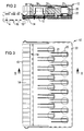
- FIGS 4 and 5 are in a similar protective assembly as in Figures 2 and 3, the surge arrester 20 also divided into two rows, two each Surge arrester 20 in pairs without lateral offset are arranged one behind the other.
- the spring tongues 21 for the front surge arresters 20 protrude from the front forth towards the back, where the spring tongues 21 for the rear surge arrester 20 from the back towards the front and to the front spring tongues 21 are arranged in pairs aligned. Since the spring tongues no longer overlap, it is possible the pitch between the surge arresters to reduce or use larger surge arresters to use cheaper features.
Landscapes
- Structure Of Telephone Exchanges (AREA)
- Emergency Protection Circuit Devices (AREA)
- Paper (AREA)
- Details Of Aerials (AREA)
- Input Circuits Of Receivers And Coupling Of Receivers And Audio Equipment (AREA)
- Ignition Installations For Internal Combustion Engines (AREA)
- Transmitters (AREA)
- Exchange Systems With Centralized Control (AREA)
Claims (3)
- Sous-groupe (12) de protection pour le raccordement par enfichage à une pièce (4) de contact d'un distributeur dans une installation de télécommunication, le sous-groupe (12) de protection comportant une pièce (17, 18) de support plane et une pluralité de para-surtensions à deux pôles qui reposent en une ou plusieurs rangées sur la pièce de support par l'un de leurs pôles, une tôle (22) de mise à la terre, qui entoure en forme de U la pièce (17, 18) de support, étant munie de languettes (21) élastiques qui s'appliquent à l'autre pôle des para-surtensions (20) et les repoussent sur la pièce (17, 18) de support, la pièce (17, 18) de support étant munie sur sa face (13) frontale d'une rangée de points (14) de contact par enfichage, qui peuvent être mis en contact avec la pièce (4) de contact, et la tôle (22) de mise à la terre pouvant être emmanchée depuis la face arrière faisant face à la face (13) frontale sur la pièce (17, 18) de support comportant les para-surtensions (20), caractérisé en ce que la branche de la tôle (22) de mise à la terre qui repose sur les para-surtensions (20) prolonge les para-surtensions d'à peu près la longueur des languettes (21) élastiques en direction de la face (13) frontale, en ce que l'extrémité côté frontal de la branche est ancré à la pièce (17, 18) de support, en ce que les languettes (21) élastiques sont réalisées en pattes dégagées par découpage et en ce qu'au moins une partie des languettes (21) élastiques est réalisée de manière à faire saillie librement de la face (13) frontale vers la face arrière.
- Sous-groupe de protection suivant la revendication 1, caractérisé en ce que les surtensions (20) sont disposées en deux rangées distinctes, décalées latéralement l'une par rapport à l'autre, et en ce que les languettes (21) élastiques sont réalisées en étant décalées les unes par rapport aux autres en faisant saillie librement vers la face arrière.
- Sous-groupe de protection suivant la revendication 1, caractérisé en ce que les deux rangées des surtensions (20) sont disposées sans décalage latéral, en ce que chaque fois deux surtensions (20) sont disposées l'une derrière l'autre dans la direction d'enfichage, en ce qu'une rangée des languettes (21) élastiques prévues pour les surtensions (20) avant font saillie de la face (13) frontale en direction de la face arrière, et en ce que les autres rangées des languettes (21) élastiques prévues pour les surtensions (20) côté arrière font saillie de la face arrière en direction de la face (13) frontale.
Applications Claiming Priority (3)
| Application Number | Priority Date | Filing Date | Title |
|---|---|---|---|
| DE19612448 | 1996-03-28 | ||
| DE19612448 | 1996-03-28 | ||
| PCT/DE1997/000630 WO1997037408A1 (fr) | 1996-03-28 | 1997-03-27 | Sous-groupe de protection d'un distributeur dans un systeme de telecommunications |
Publications (2)
| Publication Number | Publication Date |
|---|---|
| EP0890206A1 EP0890206A1 (fr) | 1999-01-13 |
| EP0890206B1 true EP0890206B1 (fr) | 1999-12-01 |
Family
ID=7789790
Family Applications (1)
| Application Number | Title | Priority Date | Filing Date |
|---|---|---|---|
| EP97921590A Expired - Lifetime EP0890206B1 (fr) | 1996-03-28 | 1997-03-27 | Sous-groupe de protection d'un distributeur dans un systeme de telecommunications |
Country Status (6)
| Country | Link |
|---|---|
| EP (1) | EP0890206B1 (fr) |
| AT (1) | ATE187286T1 (fr) |
| AU (1) | AU2762097A (fr) |
| DE (1) | DE59700798D1 (fr) |
| ES (1) | ES2140977T3 (fr) |
| WO (1) | WO1997037408A1 (fr) |
Families Citing this family (1)
| Publication number | Priority date | Publication date | Assignee | Title |
|---|---|---|---|---|
| DE10317621B4 (de) | 2003-04-16 | 2016-07-07 | Tyco Electronics Services Gmbh | Überspannungsschutzmagazin für eine Einrichtung der Telekommunikationstechnik |
Family Cites Families (3)
| Publication number | Priority date | Publication date | Assignee | Title |
|---|---|---|---|---|
| DE2508845C3 (de) * | 1975-02-28 | 1980-10-02 | Siemens Ag, 1000 Berlin Und 8000 Muenchen | Sicherungsleiste |
| DE2738851C3 (de) * | 1977-08-29 | 1981-09-24 | Siemens AG, 1000 Berlin und 8000 München | Sicherungsleiste zur Halterung elektrischer Sicherungen |
| DE4225484C1 (de) * | 1992-07-30 | 1993-12-23 | Krone Ag | Schutzstecker für Anschluß- und Trennleisten der Telekommunikations- und Datentechnik |
-
1997
- 1997-03-27 DE DE59700798T patent/DE59700798D1/de not_active Expired - Fee Related
- 1997-03-27 WO PCT/DE1997/000630 patent/WO1997037408A1/fr active IP Right Grant
- 1997-03-27 AT AT97921590T patent/ATE187286T1/de active
- 1997-03-27 EP EP97921590A patent/EP0890206B1/fr not_active Expired - Lifetime
- 1997-03-27 AU AU27620/97A patent/AU2762097A/en not_active Abandoned
- 1997-03-27 ES ES97921590T patent/ES2140977T3/es not_active Expired - Lifetime
Also Published As
| Publication number | Publication date |
|---|---|
| ATE187286T1 (de) | 1999-12-15 |
| DE59700798D1 (de) | 2000-01-05 |
| ES2140977T3 (es) | 2000-03-01 |
| AU2762097A (en) | 1997-10-22 |
| WO1997037408A1 (fr) | 1997-10-09 |
| EP0890206A1 (fr) | 1999-01-13 |
Similar Documents
| Publication | Publication Date | Title |
|---|---|---|
| DE3137429C2 (de) | Anschlußeinrichtung in einer Anschlußleiste | |
| EP0399628B1 (fr) | Bloc de connexion avec protection contre la surtension | |
| EP0446572A1 (fr) | Bloc de connexion pour technique des télécommunications et de l'informatique | |
| DE2525641A1 (de) | Vorrichtung zum gleichzeitigen einsetzen jedes leitungsdrahts von zwei elektrischen leitungsdrahtgruppen in einen schlitz eines einzelnen elektrischen kontakts eines elektrischen verbinders | |
| EP0952635B1 (fr) | Connecteur électrique | |
| EP0856911A1 (fr) | Bloc de connexion multipolaire | |
| EP0890205B1 (fr) | Dispositif de distribution d'un distributeur dans un systeme de telecommunications | |
| EP0180000B1 (fr) | Dispositif à coupure comportant une pluralité de bornes à connexion sans dénudage de conducteurs électriques | |
| EP0890206B1 (fr) | Sous-groupe de protection d'un distributeur dans un systeme de telecommunications | |
| DE3922431C2 (fr) | ||
| DE3625422C2 (fr) | ||
| EP0258628B1 (fr) | Module pour protéger les lignes électriques dans des répartiteurs d'installations de télécommunication | |
| EP0822611B1 (fr) | Barette à borne notamment pour des bornes initiateurs/acteurs | |
| EP0446433B1 (fr) | Assemblage de protection pour un distributeur dans un réseau de télécommunication | |
| DE1490466A1 (de) | Schalt- und Trennleiste fuer Fernmeldeanlagen,insbesondere fuer Rangierfelder in Fernsprechvermittlungsanlagen | |
| EP0667650A2 (fr) | Système de connexion modulaire | |
| DE3311476A1 (de) | Verteilerliste mit einer mehrzahl von dem abisolierfreien anschluss elektrischer leiter gestattenden anschlussklammen | |
| DE848450T1 (de) | Anschlussvorrichtung von elektrischen Kabel mit ein oder einer Mehrzahl vom Leitern | |
| DE20014918U1 (de) | Anschlußelement zum Anschließen von Kabelschirmen | |
| EP0409109B1 (fr) | Dispositif de distribution pour une installation de télécommunication | |
| DE3921206C1 (en) | Distribution strip for telephone exchange - has contact springs extending over separating contacts and bent back to rear handling side | |
| DD295958A5 (de) | Verteilereinrichtung fuer telekommunikationsanlagen | |
| CH493948A (de) | Trennleiste für Fernmeldeanlagen | |
| EP0852078A1 (fr) | Procede de raccordement d'un connecteur femelle multipolaire | |
| WO1991014299A1 (fr) | Composant de contact pour tableaux de distribution de reseaux de telecommunications |
Legal Events
| Date | Code | Title | Description |
|---|---|---|---|
| PUAI | Public reference made under article 153(3) epc to a published international application that has entered the european phase |
Free format text: ORIGINAL CODE: 0009012 |
|
| 17P | Request for examination filed |
Effective date: 19980917 |
|
| AK | Designated contracting states |
Kind code of ref document: A1 Designated state(s): AT BE DE ES FR |
|
| GRAG | Despatch of communication of intention to grant |
Free format text: ORIGINAL CODE: EPIDOS AGRA |
|
| 17Q | First examination report despatched |
Effective date: 19990205 |
|
| GRAG | Despatch of communication of intention to grant |
Free format text: ORIGINAL CODE: EPIDOS AGRA |
|
| GRAH | Despatch of communication of intention to grant a patent |
Free format text: ORIGINAL CODE: EPIDOS IGRA |
|
| GRAH | Despatch of communication of intention to grant a patent |
Free format text: ORIGINAL CODE: EPIDOS IGRA |
|
| GRAA | (expected) grant |
Free format text: ORIGINAL CODE: 0009210 |
|
| AK | Designated contracting states |
Kind code of ref document: B1 Designated state(s): AT BE DE ES FR |
|
| REF | Corresponds to: |
Ref document number: 187286 Country of ref document: AT Date of ref document: 19991215 Kind code of ref document: T |
|
| REF | Corresponds to: |
Ref document number: 59700798 Country of ref document: DE Date of ref document: 20000105 |
|
| REG | Reference to a national code |
Ref country code: ES Ref legal event code: FG2A Ref document number: 2140977 Country of ref document: ES Kind code of ref document: T3 |
|
| ET | Fr: translation filed | ||
| PLBE | No opposition filed within time limit |
Free format text: ORIGINAL CODE: 0009261 |
|
| STAA | Information on the status of an ep patent application or granted ep patent |
Free format text: STATUS: NO OPPOSITION FILED WITHIN TIME LIMIT |
|
| 26N | No opposition filed | ||
| PGFP | Annual fee paid to national office [announced via postgrant information from national office to epo] |
Ref country code: AT Payment date: 20010306 Year of fee payment: 5 |
|
| PGFP | Annual fee paid to national office [announced via postgrant information from national office to epo] |
Ref country code: ES Payment date: 20010406 Year of fee payment: 5 |
|
| PGFP | Annual fee paid to national office [announced via postgrant information from national office to epo] |
Ref country code: BE Payment date: 20010410 Year of fee payment: 5 |
|
| PG25 | Lapsed in a contracting state [announced via postgrant information from national office to epo] |
Ref country code: AT Free format text: LAPSE BECAUSE OF NON-PAYMENT OF DUE FEES Effective date: 20020327 |
|
| PG25 | Lapsed in a contracting state [announced via postgrant information from national office to epo] |
Ref country code: ES Free format text: LAPSE BECAUSE OF NON-PAYMENT OF DUE FEES Effective date: 20020328 |
|
| PG25 | Lapsed in a contracting state [announced via postgrant information from national office to epo] |
Ref country code: BE Free format text: LAPSE BECAUSE OF NON-PAYMENT OF DUE FEES Effective date: 20020331 |
|
| BERE | Be: lapsed |
Owner name: *SIEMENS A.G. Effective date: 20020331 |
|
| REG | Reference to a national code |
Ref country code: ES Ref legal event code: FD2A Effective date: 20030410 |
|
| REG | Reference to a national code |
Ref country code: FR Ref legal event code: TP |
|
| PGFP | Annual fee paid to national office [announced via postgrant information from national office to epo] |
Ref country code: FR Payment date: 20060317 Year of fee payment: 10 |
|
| PGFP | Annual fee paid to national office [announced via postgrant information from national office to epo] |
Ref country code: DE Payment date: 20060502 Year of fee payment: 10 |
|
| REG | Reference to a national code |
Ref country code: FR Ref legal event code: ST Effective date: 20071130 |
|
| PG25 | Lapsed in a contracting state [announced via postgrant information from national office to epo] |
Ref country code: DE Free format text: LAPSE BECAUSE OF NON-PAYMENT OF DUE FEES Effective date: 20071002 |
|
| PG25 | Lapsed in a contracting state [announced via postgrant information from national office to epo] |
Ref country code: FR Free format text: LAPSE BECAUSE OF NON-PAYMENT OF DUE FEES Effective date: 20070402 |