EP0888917B2 - Vorrichtung für ein öffnungsfähiges Dach eines Kraftfahrzeugs - Google Patents
Vorrichtung für ein öffnungsfähiges Dach eines Kraftfahrzeugs Download PDFInfo
- Publication number
- EP0888917B2 EP0888917B2 EP98202047A EP98202047A EP0888917B2 EP 0888917 B2 EP0888917 B2 EP 0888917B2 EP 98202047 A EP98202047 A EP 98202047A EP 98202047 A EP98202047 A EP 98202047A EP 0888917 B2 EP0888917 B2 EP 0888917B2
- Authority
- EP
- European Patent Office
- Prior art keywords
- slideshoe
- closing element
- longitudinal guide
- pin
- roof construction
- Prior art date
- Legal status (The legal status is an assumption and is not a legal conclusion. Google has not performed a legal analysis and makes no representation as to the accuracy of the status listed.)
- Expired - Lifetime
Links
- 238000010276 construction Methods 0.000 title claims description 23
- 230000008878 coupling Effects 0.000 claims description 29
- 238000010168 coupling process Methods 0.000 claims description 29
- 238000005859 coupling reaction Methods 0.000 claims description 29
- 230000000694 effects Effects 0.000 claims description 3
- 238000007789 sealing Methods 0.000 description 4
- 230000007704 transition Effects 0.000 description 3
- 239000000463 material Substances 0.000 description 2
- XAGFODPZIPBFFR-UHFFFAOYSA-N aluminium Chemical compound [Al] XAGFODPZIPBFFR-UHFFFAOYSA-N 0.000 description 1
- 229910052782 aluminium Inorganic materials 0.000 description 1
- 239000004411 aluminium Substances 0.000 description 1
- 230000001419 dependent effect Effects 0.000 description 1
- 239000011521 glass Substances 0.000 description 1
- XLYOFNOQVPJJNP-UHFFFAOYSA-N water Substances O XLYOFNOQVPJJNP-UHFFFAOYSA-N 0.000 description 1
Images


Classifications
-
- B—PERFORMING OPERATIONS; TRANSPORTING
- B60—VEHICLES IN GENERAL
- B60J—WINDOWS, WINDSCREENS, NON-FIXED ROOFS, DOORS, OR SIMILAR DEVICES FOR VEHICLES; REMOVABLE EXTERNAL PROTECTIVE COVERINGS SPECIALLY ADAPTED FOR VEHICLES
- B60J7/00—Non-fixed roofs; Roofs with movable panels, e.g. rotary sunroofs
- B60J7/02—Non-fixed roofs; Roofs with movable panels, e.g. rotary sunroofs of sliding type, e.g. comprising guide shoes
- B60J7/04—Non-fixed roofs; Roofs with movable panels, e.g. rotary sunroofs of sliding type, e.g. comprising guide shoes with rigid plate-like element or elements, e.g. open roofs with harmonica-type folding rigid panels
- B60J7/043—Sunroofs e.g. sliding above the roof
- B60J7/0435—Sunroofs e.g. sliding above the roof pivoting upwardly to vent mode and moving at the outside of the roof to fully open mode
Definitions
- the present invention relates to an open roof construction for a vehicle.
- the object of the present invention is to further improve such an open roof construction.
- the invention provides an open roof construction as defined in claim 1.
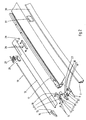
- FIG. 1 show an embodiment of an open roof construction for a vehicle, in particular a motor vehicle such as a car.
- This vehicle is provided with an opening 1 in its fixed roof 2, whereby it is noted that said fixed roof 2 may either form part of the vehicle or of the open roof construction itself, which in that case makes up the entire roof of the vehicle.
- the open roof construction comprises a stationary part, such as a frame 3, and a closing element, in this case in the form of a rigid and preferably transparent panel 4, for example made of glass or of plastic material, which is movably supported by frame 3.
- panel 4 is movable between a closed position, in which roof opening 1 is closed and panel 4 is at least substantially coplanar with the fixed roof 2, and an open position, in which panel 4 occupies a rearward position, at least partially above fixed roof 2, in which a very large part of opening 2 is cleared.
- a mechanism 5 is provided on each longitudinal side of panel 4 for effecting the movements of panel 4, which mechanism supports panel 4 and which is guided in a first longitudinal guide 6, which forms part of frame 3 and which extends along the side edge of roof opening 1, at a lower level than fixed roof 2. Furthermore, a second longitudinal guide 7 is provided, namely on the fixed roof, substantially rearward of the roof opening 1 and at a higher level than the first longitudinal guide 6. In this case the second longitudinal guide 7 extends, as seen in in lateral direction, outwardly of first longitudinal guide 6, and also outwardly of the side edges of panel 4.
- Fig. 2 clearly shows the first longitudinal guide 6 in the form of an extruded section or an injection-moulded member, which comprises a main rail and auxiliary grooves for guiding the various parts of mechanism 5.
- Said mechanism comprises a front slideshoe 8 on the front side of the panel, which is in this case connected to a driving element, such as an electric motor or a crank, via a pull-push cable 9.
- the front slideshoe 8 is provided with a cross pin 10, which is in engagement with a guide slot 11 in a front support 12, which is attached to a side flange 13, which forms part of panel 4 and which is positioned under the side edge thereof.
- Guide slot 11 comprises a front, at least approximately horizontal part 11', and a downwardly sloping rear part 11'', which joins the rear side of said front part 11'.
- guide slot 11 is closed at both ends, so that cross pin 10 will remain in constant engagement with guide slot 11.
- support 12 is provided with a cross pin 14, which is capable of engaging in a guide slot 15 in an element 16 which in principle forms part of the first longitudinal guide 6, and which is rigidly mounted thereon.
- Said guide slot 15 extends in upward and rearward direction from the front side, in a slightly curved or possibly straight path, and it is open on the rear side, so that cross pin 14 can exit said guide slot 15, after which cross pin 14 will land in a horizontal slot 17 in longitudinal guide 6, whereby slots 15 and 17 can be regarded as one slot.
- Fig. 3 furthermore shows a coupling element 18, which can provide a temporary coupling, via a pull-push cable 19 or another pressure-rigid connecting element, between the front slideshoe 8 and part of mechanism 5 which are yet to be described in more detail.
- Coupling element 18 is guided in longitudinal guide 6, and it comprises a stop member 20 near its front end, against which slideshoe 8 can strike when moving in forward direction.
- a temporary coupling between coupling element 18 and front slideshoe 8 upon rearward movement of slideshoe 8 can be provided by a coupling element in the shape of a hook 21, which pivots in vertical direction about a pin 22 on front slideshoe 8, and which can engage with its nose in a recess 23 in the upper surface of coupling element 18, so as to effect a coupling between coupling element 18 and front slideshoe 8.
- Hook 21 is biassed in upward direction, that is, in a direction in which hook 21 moves out of the recess, by means of a torsion spring 24, whilst the downward movement, that is, in the coupling direction, is controlled by the movement of the front support 12 with respect to coupling element 18, to which end the bottom side of front support 12, which is configured as a camway 25, is in engagement with the upper side of hook 21.
- coupling element 18, together with pull-push cable 19, provides a temporary coupling between front slideshoe 8 and a rear slideshoe 26, which is configured as a locking element or locking mechanism for locking and/or properly sealing panel 4 in the closed position thereof.
- the rear slideshoe 26 is to this end provided with a locking slot 27, which is open on its front side and which slopes downwards in a slightly curved path from the front side, and which is closed at its rear end.
- a locking pin 28, which is attached to side flange 13, can come into engagement with said locking slot 27 near the closed position of the panel.
- An outwardly projecting pin 29 is furthermore mounted on the side flange 13 of panel 4, near the rear side of said panel, which projecting pin 29 functions as a guide element and which is in constant engagement with second longitudinal guide 7, which is configured as a guide slot.
- the longer horizontal part of the guide slot of second longitudinal guide 7 is accommodated in an extruded section or an injection-moulded member 30, whilst the front part of the longitudinal guide, which has a curved configuration, is provided in a separate block 31 of plastic material or of aluminium, which is mounted on the front side of extruded section 30.
- Present at the front end of second longitudinal guide 7 are a short, at least approximately vertical locking part 7', and an upwardly and rearwardly sloping part 7', which joins part 7', and which joins further horizontal part 7''' at its other end.
- Fig. 4 furthermore shows that the sealing of the panel in the closed position takes place by means of a rigidly mounted sealing section 32, which forms a seal against the underside of the panel. The space outwardly thereof forms the wet part, which may function as a water drain.
- Fig. 4 furthermore shows that a cover 33 could be provided on the outside of second longitudinal guide 7, in order to integrate second longitudinal guide 7 more into the roof.
- FIGs. 1A and 3A show panel 4 in its closed and locked position.
- Cross pin 10 of front slideshoe 8 is positioned at the front end of guide slot 11 of front support 12, whilst cross pin 14 of front support 12 is positioned at the front end of guide slot 15.
- Hook 21 on front slideshoe 8 is in engagement with recess 23 of coupling element 18 (see also the separate sectional view of Fig. 1), so that the front and rear slideshoes 8 and 26 respectively are coupled via coupling element 18, 19.
- Locking pin 28 of panel 4 is positioned exactly at the rear end of locking slot 27 in rear slideshoe 26.
- the rear guide pin 29 is positioned at the bottom end of vertical locking part 7' of second longitudinal guide 7.
- locking slot 27 is moved with respect to locking pin 28, and locking pin 28 has exited the very short horizontal part, which functions to allow some play and provide stability for the panel movement, and has arrived in the sloping part, so that the panel has moved upwards over a small distance on the rear side, as a result of which also guide pin 29 has moved slightly upwards in vertical locking part 7' of second longitudinal guide 7.
- panel 4 has in the meantime become detached from sealing section 32 at the rear edge.
- Figs. 1D and 3D show slideshoe 8 to have moved further rearwardly, whereby pins 10 and 14 have been moved further in guide slots 11 and 15 respectively, and whereby locking pin 28 has completely exited locking slot 27 on the rear side of the panel, so that control of the movement of the rear side of panel 4 has been taken over by guide pin 29, which moves in the sloping part 7'' of longitudinal guide 7.
- front support 12 has moved so far upwardly with respect to coupling element 18, that the nose of hook 21 of front slideshoe 8 nearly exits recess 23 in coupling element 18.
- Front support 13 has in the meantime been moved so far in horizontal and vertical direction with respect to coupling element 18, that hook 21 has been completely removed from recess 23 by means of torsion spring 24, as a result of which front slideshoe 8 and rear slideshoe 26 are no longer coupled, so that rear slideshoe 26, and thus the locking mechanism, remain stationary.
- a spring (not shown), for example a tension spring, which engages rear slideshoe 26 or one of the other parts of the locking mechanism, provides a rearward load on rear slideshoe 26, ensuring thereby that said slideshoe will remain in its rearmost position until front slideshoe 8 meets the stop of coupling element 18, after which hook 21 effects the coupling between slideshoe 8 and coupling element 18 again.
- the invention provides an open roof construction which comprises a panel which is supported in a stable manner, and which enables movement in such a manner that the panel can be moved in rearward direction quite close to the fixed roof, to such a large extent that the larger part of the roof opening is cleared.
Landscapes
- Engineering & Computer Science (AREA)
- Mechanical Engineering (AREA)
- Body Structure For Vehicles (AREA)
- Fittings On The Vehicle Exterior For Carrying Loads, And Devices For Holding Or Mounting Articles (AREA)
- Seal Device For Vehicle (AREA)
Claims (8)
- Offendachkonstruktion für ein Fahrzeug mit einer Öffnung(1) in dessen Festdach (2), aufweisend: ein stationäres Teil (3), welches an dem Dach des Fahrzeugs zu befestigen ist, und ein bewegbares Verschlusselement (4), welches von dem stationären Teil bewegbar gehalten und mittels einer Antriebseinheit (9) verstellbar ist, wobei das Verschlusselement zwischen einer Schließposition, in welcher die Dachöffnung verschlossen ist, und einer hinteren Offenposition bewegbar ist, zumindest teilweise über das Festdach, in welcher die Dachöffnung zumindest teilweise freigegeben ist, wobei das stationäre Teil mit mindestens einer ersten Längsführung (6), die sich entlang der Dachöffnung erstreckt, und mit einer zweiten Längsführung (7) an dem Festdach hinter der Dachöffnung versehen ist, wobei die zweite Längsführung (7) einen vorderen, im Wesentlichen vertikalen Teil (7') und einen weiteren Teil (7'') aufweist, der der oberen Seite des vorderen Teils angrenzt, wohingegen das Verschlusselement nahe seiner Vorderseite von einem in der ersten Führungsschiene verschiebbar gehaltenen Gleitstück (8) gehalten ist und rückwärts davon von einem Führungselement (29) gehalten ist, welches in der zweiten Längsführung zur Gleitbewegung imstande ist, und ferner einen Mechanismus (26 - 28) an der Rückseite der Offendachkonstruktion aufweist, welcher von der Antriebseinheit angetrieben ist und temporär in Eingriff mit dem Verschlusselement (4) nahe von dessen Schließposition steht, und welcher die Bewegung des Verschlussmittels bewirkt, wenn das Führungselement (29) des Verschlusselements in dem im Wesentlichen vertikalen, vorderen Teil (7') der zweiten Längsführung (7) präsent ist, dadurch gekennzeichnet, dass der vordere Teil kurz ist und sich nur zu einem Anteil der Vertikal-Ausdehnung der zweiten Längsführung erstreckt, wobei der Mechanismus (26 - 28) ein Arretierungsmechanismus ist, welcher das Verschlusselement (4) nur nahe von dessen Schließposition ergreift, derart dass nur ein kleiner Anteil der Vertikal-Bewegung des Verschlusselements hin zu und weg aus der Schließposition von dem Arretierungsmechanismus bestimmt wird, wobei der Rest der Vertikal-Bewegung hin zu und weg aus der Schließposition von dem weiteren Teil (7'') der zweiten Längsführung bewirkt wird, welcher sich aufwärts und rückwärts erstreckt..
- Offendachkonstruktion gemäß Anspruch 1, wobei die Antriebseinheit (9) im Eingriff mit dem vorderen Gleitstück (8) steht, wobei ein lösbares Kupplungselement (18, 19) zwischen dem vorderen Gleitstück und vorzugsweise einem hinteren Gleitstück (26) des Arretierungsmechanismus (26-28) bereitgestellt ist zum temporären Antreiben des Arretierungsmechanismus.
- Offendachkonstruktion gemäß Anspruch 2, wobei der Arretierungsmechanismus eine Stiftschlitzverbindung aufweist, wobei der eine von dem Stift und von dem Schlitz an dem Verschlusselement vorhanden ist und der andere von dem Stift und von dem Schlitz an dem hinteren Gleitstück vorhanden ist.
- Offendachkonstruktion gemäß Anspruch 2 oder 3, wobei das Verschlusselement an seiner Vorderseite ein Element zum Höhenverstellen aufweist, welches Element mit dem Gleitstück im verschiebbaren Eingriff steht, wobei das Kupplungselement mit einem Kupplungselement eingerichtet ist, welches an das und von dem Gleitstück kuppelbar und abkuppelbar ist und welches mittels des Elements zum Höhenverstellen gesteuert ist.
- Offendachkonstruktion gemäß Anspruch 4, wobei das Kupplungselement sich aus einem um einen horizontalen Stift am Gleitstück schwenkbaren Haken zusammensetzt, welcher imstande ist, sich seinerseits in eine und von einer Öffnung in dem Kupplungselement einzukuppeln und abzukuppeln, und welcher mittels der Bodenseite des Elements zum Höhenverstellen gesteuert ist.
- Offendachkonstruktion gemäß einem der vorgehenden Ansprüche, wobei zwei Längsführungen bereitgestellt sind, welche an beiden Seiten des Verschlusselements positioniert sind, wenn das Verschlusselement in seiner Offenposition ist, wobei die Längsführungen jeweils mit mindestens einem Längsschlitz versehen sind, in welchen ein Stift des Verschlusselements eingreift, welcher Stift an einem Flansch zum Halten des Paneels montiert ist.
- Offendachkonstruktion gemäß Anspruch 6, wobei das Verschlusselement an seiner Vorderseite mittels einer Vorrichtung zum Höhenverstellen vertikal verstellbar gehalten ist, welche an dem vorderen Gleitstück vorhanden ist, welche Vorrichtung zum Höhenverstellen derartig konstruiert ist, dass die Höhenverstellung zumindest teilweise so während der Bewegung des Verschlusselements in Längsrichtung stattfindet.
- Offendachkonstruktion gemäß Anspruch 7, wobei die Vorrichtung zum Höhenverstellen als Halter konfiguriert ist, welcher an dem Verschlusselement montiert ist, welcher an einem Antriebsläufer der Antriebseinheit angeschlossen ist, welcher sich in der ersten Längsführung und mit der Längsführung über zwei sich überschneidende Stiftschlitzverbindungen während der Höhenverstellung bewegt.
Applications Claiming Priority (2)
| Application Number | Priority Date | Filing Date | Title |
|---|---|---|---|
| NL1006437A NL1006437C2 (nl) | 1997-07-01 | 1997-07-01 | Open-dakconstructie voor een voertuig. |
| NL1006437 | 1997-07-01 |
Publications (3)
| Publication Number | Publication Date |
|---|---|
| EP0888917A1 EP0888917A1 (de) | 1999-01-07 |
| EP0888917B1 EP0888917B1 (de) | 2004-09-01 |
| EP0888917B2 true EP0888917B2 (de) | 2007-06-13 |
Family
ID=19765250
Family Applications (1)
| Application Number | Title | Priority Date | Filing Date |
|---|---|---|---|
| EP98202047A Expired - Lifetime EP0888917B2 (de) | 1997-07-01 | 1998-06-18 | Vorrichtung für ein öffnungsfähiges Dach eines Kraftfahrzeugs |
Country Status (5)
| Country | Link |
|---|---|
| US (1) | US6012768A (de) |
| EP (1) | EP0888917B2 (de) |
| JP (1) | JP4101360B2 (de) |
| DE (1) | DE69825945T3 (de) |
| NL (1) | NL1006437C2 (de) |
Families Citing this family (10)
| Publication number | Priority date | Publication date | Assignee | Title |
|---|---|---|---|---|
| US6860549B2 (en) | 2000-11-20 | 2005-03-01 | Arvin Meritor Technology, Llc. | Retractable roof panel |
| DE60128878T2 (de) | 2000-11-20 | 2008-02-28 | ArvinMeritor Technology, LLC, Troy | Fahrzeug |
| DE102005043019B4 (de) * | 2005-09-09 | 2008-02-14 | Webasto Ag | Fahrzeugdach mit mindestens zwei Deckelelementen |
| EP1844967A1 (de) * | 2006-04-04 | 2007-10-17 | ArvinMeritor GmbH | Schiebedachsystem |
| FR2973295B1 (fr) * | 2011-04-04 | 2013-03-29 | Acs France Sas | Pavillon vitre a panneau mobile coulissant et entrebaillant. |
| EP2607125B2 (de) * | 2011-12-22 | 2017-03-01 | Inalfa Roof Systems Group B.V. | Schließmechanismus für öffenbare Dachkonstruktion und damit ausgettatete öffenbare Dachkonstruktion |
| US11440385B2 (en) | 2017-08-03 | 2022-09-13 | Inalfa Roof Systems Group B.V. | Open roof construction for a vehicle |
| DE102019113142A1 (de) * | 2019-05-17 | 2020-11-19 | Webasto SE | Anordnung und Verfahren zum Bewegen eines Deckels |
| CN112440697B (zh) | 2019-08-27 | 2023-11-24 | 英纳法天窗系统集团有限公司 | 遮阳系统及其部件的制造方法 |
| EP3795396B1 (de) | 2019-09-19 | 2025-08-20 | Inalfa Roof Systems Group B.V. | Führungsanordnung für ein offenes dachsystem und verfahren zur wartung der führungsanordnung |
Citations (2)
| Publication number | Priority date | Publication date | Assignee | Title |
|---|---|---|---|---|
| EP0584496B1 (de) † | 1992-08-19 | 1995-10-04 | WEBASTO KAROSSERIESYSTEME GmbH | Fahrzeugdach |
| EP0863817B1 (de) † | 1996-10-01 | 2003-07-30 | WEBASTO KAROSSERIESYSTEME GmbH | Fahrzeugdach mit wenigstens einem deckel |
Family Cites Families (9)
| Publication number | Priority date | Publication date | Assignee | Title |
|---|---|---|---|---|
| FR2384640A1 (fr) | 1977-03-23 | 1978-10-20 | Peugeot | Mecanisme de toit ouvrant a commande manuelle pour vehicule automobile |
| NL179196C (nl) * | 1980-06-24 | 1986-08-01 | Vermeulen Hollandia Octrooien | Schuifdak voor een voertuig. |
| NL182461C (nl) * | 1982-12-30 | 1988-03-16 | Vermeulen Hollandia Octrooien | Schuifdak voor een voertuig. |
| NL8701492A (nl) * | 1987-06-25 | 1989-01-16 | Vermeulen Hollandia Octrooien | Open dakconstructie voor een voertuig. |
| NL9100972A (nl) * | 1991-06-06 | 1993-01-04 | Vermeulen Hollandia Octrooien | Hef-schuifdak voor een voertuig. |
| NL9101707A (nl) * | 1991-10-14 | 1993-05-03 | Vermeulen Hollandia Octrooien | Open-dakconstructie voor een voertuig. |
| DE4227400C2 (de) * | 1992-08-19 | 1997-07-17 | Webasto Karosseriesysteme | Schiebedach |
| DE4238945C1 (de) * | 1992-11-19 | 1993-11-25 | Webasto Karosseriesysteme | Hebeschiebedach für Fahrzeuge |
| DE4238944C1 (de) * | 1992-11-19 | 1993-10-14 | Webasto Karosseriesysteme | Fahrzeugdach |
-
1997
- 1997-07-01 NL NL1006437A patent/NL1006437C2/nl not_active IP Right Cessation
-
1998
- 1998-06-18 DE DE69825945T patent/DE69825945T3/de not_active Expired - Lifetime
- 1998-06-18 EP EP98202047A patent/EP0888917B2/de not_active Expired - Lifetime
- 1998-06-23 US US09/103,204 patent/US6012768A/en not_active Expired - Lifetime
- 1998-06-24 JP JP17779998A patent/JP4101360B2/ja not_active Expired - Fee Related
Patent Citations (2)
| Publication number | Priority date | Publication date | Assignee | Title |
|---|---|---|---|---|
| EP0584496B1 (de) † | 1992-08-19 | 1995-10-04 | WEBASTO KAROSSERIESYSTEME GmbH | Fahrzeugdach |
| EP0863817B1 (de) † | 1996-10-01 | 2003-07-30 | WEBASTO KAROSSERIESYSTEME GmbH | Fahrzeugdach mit wenigstens einem deckel |
Also Published As
| Publication number | Publication date |
|---|---|
| DE69825945T2 (de) | 2005-09-08 |
| DE69825945T3 (de) | 2008-01-17 |
| EP0888917B1 (de) | 2004-09-01 |
| NL1006437C2 (nl) | 1999-01-05 |
| JPH1159193A (ja) | 1999-03-02 |
| DE69825945D1 (de) | 2004-10-07 |
| JP4101360B2 (ja) | 2008-06-18 |
| US6012768A (en) | 2000-01-11 |
| EP0888917A1 (de) | 1999-01-07 |
Similar Documents
| Publication | Publication Date | Title |
|---|---|---|
| EP1009644B1 (de) | Verfahren zum öffnen und schliessen einer öffnungsfähigen dachherstellung für ein fahrzeug mit einer öffnung im festen dach, sowie solche öffnungsfähige dachherstellung | |
| EP0888917B2 (de) | Vorrichtung für ein öffnungsfähiges Dach eines Kraftfahrzeugs | |
| US6325453B1 (en) | Open roof construction for a vehicle | |
| EP1095807B1 (de) | Öffnungsfähige Dachkonstruktion für ein Fahrzeug | |
| EP1046529B1 (de) | Konstruktion eines öffnungsfähigen Fahrzeugdaches | |
| EP1468856B1 (de) | Konstruktion eines öffnungsfähigen Fahrzeugdaches | |
| GB2094723A (en) | Sliding-raising roof for motor vehicles | |
| US6957851B2 (en) | Open roof construction for a vehicle, and method of moving a closure element thereof | |
| SE462840B (sv) | Skjut-lyft-tak foer motorfordon | |
| EP0140491B1 (de) | Schiebedach für Motorfahrzeuge | |
| US11273693B2 (en) | Roof system for a vehicle | |
| EP1070615B1 (de) | Konstruktion eines öffnungsfähigen Fahrzeugdaches | |
| EP1331119B1 (de) | Fahrzeug mit Hebeschiebedach | |
| US4895410A (en) | Sliding and lifting roofs | |
| JPH04124514U (ja) | サンルーフ装置のフレーム構造 | |
| US7296851B2 (en) | Vehicle roof | |
| JPH04262919A (ja) | 車両ルーフ | |
| EP1046530A1 (de) | Konstruktion eines öffnungsfähigen Fahrzeugdaches | |
| EP0899138B1 (de) | Öffnungsfähige Dachkonstruktion für ein Fahrzeug | |
| EP0106610B1 (de) | Schiebedach für Kraftfahrzeuge |
Legal Events
| Date | Code | Title | Description |
|---|---|---|---|
| PUAI | Public reference made under article 153(3) epc to a published international application that has entered the european phase |
Free format text: ORIGINAL CODE: 0009012 |
|
| AK | Designated contracting states |
Kind code of ref document: A1 Designated state(s): DE FR GB IT NL SE |
|
| AX | Request for extension of the european patent |
Free format text: AL;LT;LV;MK;RO;SI |
|
| 17P | Request for examination filed |
Effective date: 19990618 |
|
| AKX | Designation fees paid |
Free format text: DE FR GB IT NL SE |
|
| 17Q | First examination report despatched |
Effective date: 20010809 |
|
| RAP1 | Party data changed (applicant data changed or rights of an application transferred) |
Owner name: INALFA ROOF SYSTEMS GROUP B.V. |
|
| GRAP | Despatch of communication of intention to grant a patent |
Free format text: ORIGINAL CODE: EPIDOSNIGR1 |
|
| GRAS | Grant fee paid |
Free format text: ORIGINAL CODE: EPIDOSNIGR3 |
|
| GRAA | (expected) grant |
Free format text: ORIGINAL CODE: 0009210 |
|
| AK | Designated contracting states |
Kind code of ref document: B1 Designated state(s): DE FR GB IT NL SE |
|
| PG25 | Lapsed in a contracting state [announced via postgrant information from national office to epo] |
Ref country code: NL Free format text: LAPSE BECAUSE OF FAILURE TO SUBMIT A TRANSLATION OF THE DESCRIPTION OR TO PAY THE FEE WITHIN THE PRESCRIBED TIME-LIMIT Effective date: 20040901 Ref country code: IT Free format text: LAPSE BECAUSE OF FAILURE TO SUBMIT A TRANSLATION OF THE DESCRIPTION OR TO PAY THE FEE WITHIN THE PRESCRIBED TIME-LIMIT;WARNING: LAPSES OF ITALIAN PATENTS WITH EFFECTIVE DATE BEFORE 2007 MAY HAVE OCCURRED AT ANY TIME BEFORE 2007. THE CORRECT EFFECTIVE DATE MAY BE DIFFERENT FROM THE ONE RECORDED. Effective date: 20040901 |
|
| REG | Reference to a national code |
Ref country code: GB Ref legal event code: FG4D |
|
| REF | Corresponds to: |
Ref document number: 69825945 Country of ref document: DE Date of ref document: 20041007 Kind code of ref document: P |
|
| PG25 | Lapsed in a contracting state [announced via postgrant information from national office to epo] |
Ref country code: SE Free format text: LAPSE BECAUSE OF FAILURE TO SUBMIT A TRANSLATION OF THE DESCRIPTION OR TO PAY THE FEE WITHIN THE PRESCRIBED TIME-LIMIT Effective date: 20041201 |
|
| NLV1 | Nl: lapsed or annulled due to failure to fulfill the requirements of art. 29p and 29m of the patents act | ||
| PLAQ | Examination of admissibility of opposition: information related to despatch of communication + time limit deleted |
Free format text: ORIGINAL CODE: EPIDOSDOPE2 |
|
| PLBQ | Unpublished change to opponent data |
Free format text: ORIGINAL CODE: EPIDOS OPPO |
|
| PLBI | Opposition filed |
Free format text: ORIGINAL CODE: 0009260 |
|
| PLAQ | Examination of admissibility of opposition: information related to despatch of communication + time limit deleted |
Free format text: ORIGINAL CODE: EPIDOSDOPE2 |
|
| PLAR | Examination of admissibility of opposition: information related to receipt of reply deleted |
Free format text: ORIGINAL CODE: EPIDOSDOPE4 |
|
| PLBQ | Unpublished change to opponent data |
Free format text: ORIGINAL CODE: EPIDOS OPPO |
|
| PLAB | Opposition data, opponent's data or that of the opponent's representative modified |
Free format text: ORIGINAL CODE: 0009299OPPO |
|
| PLAB | Opposition data, opponent's data or that of the opponent's representative modified |
Free format text: ORIGINAL CODE: 0009299OPPO |
|
| PLAQ | Examination of admissibility of opposition: information related to despatch of communication + time limit deleted |
Free format text: ORIGINAL CODE: EPIDOSDOPE2 |
|
| PLAR | Examination of admissibility of opposition: information related to receipt of reply deleted |
Free format text: ORIGINAL CODE: EPIDOSDOPE4 |
|
| PLAX | Notice of opposition and request to file observation + time limit sent |
Free format text: ORIGINAL CODE: EPIDOSNOBS2 |
|
| PLBQ | Unpublished change to opponent data |
Free format text: ORIGINAL CODE: EPIDOS OPPO |
|
| ET | Fr: translation filed | ||
| 26 | Opposition filed |
Opponent name: WEBASTO AG Effective date: 20050601 |
|
| R26 | Opposition filed (corrected) |
Opponent name: WEBASTO AG Effective date: 20050601 |
|
| R26 | Opposition filed (corrected) |
Opponent name: WEBASTO AG Effective date: 20050601 |
|
| PLBB | Reply of patent proprietor to notice(s) of opposition received |
Free format text: ORIGINAL CODE: EPIDOSNOBS3 |
|
| PUAH | Patent maintained in amended form |
Free format text: ORIGINAL CODE: 0009272 |
|
| STAA | Information on the status of an ep patent application or granted ep patent |
Free format text: STATUS: PATENT MAINTAINED AS AMENDED |
|
| 27A | Patent maintained in amended form |
Effective date: 20070613 |
|
| AK | Designated contracting states |
Kind code of ref document: B2 Designated state(s): DE FR GB IT NL SE |
|
| ET3 | Fr: translation filed ** decision concerning opposition | ||
| PGFP | Annual fee paid to national office [announced via postgrant information from national office to epo] |
Ref country code: GB Payment date: 20080623 Year of fee payment: 11 |
|
| GBPC | Gb: european patent ceased through non-payment of renewal fee |
Effective date: 20090618 |
|
| PG25 | Lapsed in a contracting state [announced via postgrant information from national office to epo] |
Ref country code: GB Free format text: LAPSE BECAUSE OF NON-PAYMENT OF DUE FEES Effective date: 20090618 |
|
| PGFP | Annual fee paid to national office [announced via postgrant information from national office to epo] |
Ref country code: DE Payment date: 20130625 Year of fee payment: 16 |
|
| PGFP | Annual fee paid to national office [announced via postgrant information from national office to epo] |
Ref country code: FR Payment date: 20130726 Year of fee payment: 16 |
|
| REG | Reference to a national code |
Ref country code: DE Ref legal event code: R119 Ref document number: 69825945 Country of ref document: DE |
|
| REG | Reference to a national code |
Ref country code: DE Ref legal event code: R119 Ref document number: 69825945 Country of ref document: DE Effective date: 20150101 |
|
| REG | Reference to a national code |
Ref country code: FR Ref legal event code: ST Effective date: 20150227 |
|
| PG25 | Lapsed in a contracting state [announced via postgrant information from national office to epo] |
Ref country code: DE Free format text: LAPSE BECAUSE OF NON-PAYMENT OF DUE FEES Effective date: 20150101 |
|
| PG25 | Lapsed in a contracting state [announced via postgrant information from national office to epo] |
Ref country code: FR Free format text: LAPSE BECAUSE OF NON-PAYMENT OF DUE FEES Effective date: 20140630 |