EP0885777A1 - Trim member including intermittent bright strip and method of making same - Google Patents
Trim member including intermittent bright strip and method of making same Download PDFInfo
- Publication number
- EP0885777A1 EP0885777A1 EP97304276A EP97304276A EP0885777A1 EP 0885777 A1 EP0885777 A1 EP 0885777A1 EP 97304276 A EP97304276 A EP 97304276A EP 97304276 A EP97304276 A EP 97304276A EP 0885777 A1 EP0885777 A1 EP 0885777A1
- Authority
- EP
- European Patent Office
- Prior art keywords
- strip
- sections
- strip sections
- bright
- providing
- Prior art date
- Legal status (The legal status is an assumption and is not a legal conclusion. Google has not performed a legal analysis and makes no representation as to the accuracy of the status listed.)
- Withdrawn
Links
- 238000004519 manufacturing process Methods 0.000 title 1
- 238000000034 method Methods 0.000 claims abstract description 47
- 229920001169 thermoplastic Polymers 0.000 claims abstract description 15
- 239000004416 thermosoftening plastic Substances 0.000 claims abstract description 15
- 238000001125 extrusion Methods 0.000 claims description 67
- 239000000463 material Substances 0.000 claims description 18
- 239000012815 thermoplastic material Substances 0.000 claims description 14
- 229920002799 BoPET Polymers 0.000 claims description 5
- VYZAMTAEIAYCRO-UHFFFAOYSA-N Chromium Chemical compound [Cr] VYZAMTAEIAYCRO-UHFFFAOYSA-N 0.000 claims description 5
- 239000005041 Mylar™ Substances 0.000 claims description 5
- 239000000155 melt Substances 0.000 abstract description 27
- 239000010410 layer Substances 0.000 description 9
- 230000000087 stabilizing effect Effects 0.000 description 5
- 230000001681 protective effect Effects 0.000 description 3
- 238000001816 cooling Methods 0.000 description 2
- 230000007246 mechanism Effects 0.000 description 2
- 239000004033 plastic Substances 0.000 description 2
- 229920003023 plastic Polymers 0.000 description 2
- 230000006641 stabilisation Effects 0.000 description 2
- 238000011105 stabilization Methods 0.000 description 2
- 238000005034 decoration Methods 0.000 description 1
- 229920001971 elastomer Polymers 0.000 description 1
- 238000001746 injection moulding Methods 0.000 description 1
- 239000007788 liquid Substances 0.000 description 1
- 238000012986 modification Methods 0.000 description 1
- 230000004048 modification Effects 0.000 description 1
- 239000003973 paint Substances 0.000 description 1
- 239000008188 pellet Substances 0.000 description 1
- 239000004800 polyvinyl chloride Substances 0.000 description 1
- 229920000915 polyvinyl chloride Polymers 0.000 description 1
- 239000000843 powder Substances 0.000 description 1
- 239000005060 rubber Substances 0.000 description 1
- 238000011064 split stream procedure Methods 0.000 description 1
- 239000002344 surface layer Substances 0.000 description 1
- 230000001360 synchronised effect Effects 0.000 description 1
- 229920002397 thermoplastic olefin Polymers 0.000 description 1
- 229920002803 thermoplastic polyurethane Polymers 0.000 description 1
Images
Classifications
-
- B—PERFORMING OPERATIONS; TRANSPORTING
- B60—VEHICLES IN GENERAL
- B60R—VEHICLES, VEHICLE FITTINGS, OR VEHICLE PARTS, NOT OTHERWISE PROVIDED FOR
- B60R13/00—Elements for body-finishing, identifying, or decorating; Arrangements or adaptations for advertising purposes
- B60R13/04—External Ornamental or guard strips; Ornamental inscriptive devices thereon
-
- B—PERFORMING OPERATIONS; TRANSPORTING
- B29—WORKING OF PLASTICS; WORKING OF SUBSTANCES IN A PLASTIC STATE IN GENERAL
- B29C—SHAPING OR JOINING OF PLASTICS; SHAPING OF MATERIAL IN A PLASTIC STATE, NOT OTHERWISE PROVIDED FOR; AFTER-TREATMENT OF THE SHAPED PRODUCTS, e.g. REPAIRING
- B29C48/00—Extrusion moulding, i.e. expressing the moulding material through a die or nozzle which imparts the desired form; Apparatus therefor
- B29C48/001—Combinations of extrusion moulding with other shaping operations
- B29C48/0013—Extrusion moulding in several steps, i.e. components merging outside the die
- B29C48/0014—Extrusion moulding in several steps, i.e. components merging outside the die producing flat articles having components brought in contact outside the extrusion die
-
- B—PERFORMING OPERATIONS; TRANSPORTING
- B29—WORKING OF PLASTICS; WORKING OF SUBSTANCES IN A PLASTIC STATE IN GENERAL
- B29C—SHAPING OR JOINING OF PLASTICS; SHAPING OF MATERIAL IN A PLASTIC STATE, NOT OTHERWISE PROVIDED FOR; AFTER-TREATMENT OF THE SHAPED PRODUCTS, e.g. REPAIRING
- B29C48/00—Extrusion moulding, i.e. expressing the moulding material through a die or nozzle which imparts the desired form; Apparatus therefor
- B29C48/03—Extrusion moulding, i.e. expressing the moulding material through a die or nozzle which imparts the desired form; Apparatus therefor characterised by the shape of the extruded material at extrusion
- B29C48/07—Flat, e.g. panels
-
- B—PERFORMING OPERATIONS; TRANSPORTING
- B29—WORKING OF PLASTICS; WORKING OF SUBSTANCES IN A PLASTIC STATE IN GENERAL
- B29C—SHAPING OR JOINING OF PLASTICS; SHAPING OF MATERIAL IN A PLASTIC STATE, NOT OTHERWISE PROVIDED FOR; AFTER-TREATMENT OF THE SHAPED PRODUCTS, e.g. REPAIRING
- B29C48/00—Extrusion moulding, i.e. expressing the moulding material through a die or nozzle which imparts the desired form; Apparatus therefor
- B29C48/15—Extrusion moulding, i.e. expressing the moulding material through a die or nozzle which imparts the desired form; Apparatus therefor incorporating preformed parts or layers, e.g. extrusion moulding around inserts
- B29C48/157—Coating linked inserts, e.g. chains
-
- B—PERFORMING OPERATIONS; TRANSPORTING
- B29—WORKING OF PLASTICS; WORKING OF SUBSTANCES IN A PLASTIC STATE IN GENERAL
- B29C—SHAPING OR JOINING OF PLASTICS; SHAPING OF MATERIAL IN A PLASTIC STATE, NOT OTHERWISE PROVIDED FOR; AFTER-TREATMENT OF THE SHAPED PRODUCTS, e.g. REPAIRING
- B29C48/00—Extrusion moulding, i.e. expressing the moulding material through a die or nozzle which imparts the desired form; Apparatus therefor
- B29C48/16—Articles comprising two or more components, e.g. co-extruded layers
- B29C48/18—Articles comprising two or more components, e.g. co-extruded layers the components being layers
- B29C48/21—Articles comprising two or more components, e.g. co-extruded layers the components being layers the layers being joined at their surfaces
-
- B—PERFORMING OPERATIONS; TRANSPORTING
- B29—WORKING OF PLASTICS; WORKING OF SUBSTANCES IN A PLASTIC STATE IN GENERAL
- B29L—INDEXING SCHEME ASSOCIATED WITH SUBCLASS B29C, RELATING TO PARTICULAR ARTICLES
- B29L2031/00—Other particular articles
- B29L2031/30—Vehicles, e.g. ships or aircraft, or body parts thereof
- B29L2031/3005—Body finishings
- B29L2031/302—Trim strips
Definitions
- This invention relates generally to a method of producing a trim strip member including a bright strip insert and, more particularly, to a method of producing a trim strip member including intermittent bright or contrasting strip insert sections by coextruding spaced apart sections of a bright or colored strip between two continuous thermoplastic melt streams, and later cutting trim strip sections from the continuous extrusion such that the trim strip sections include spaced apart bright strip sections.
- Trim strips of this type can be formed by both injection molding processes and extrusion processes. Trim strips formed by extrusion processes have become increasingly more popular because of the versatility, efficiency and cost effectiveness of forming thermoplastic materials by known extrusion processes.
- one or more continuous, pliable thermoplastic melt streams from suitable extrusion dies are introduced into a pair of cooperating forming rolls which mold the melt streams into a continuous extrusion having a desirable shape. Trim members are then cut from the continuous extrusion after the continuous extrusion has sufficiently cooled.
- a flat base layer melt stream is coextruded onto an upper show surface layer melt stream having a desirable aesthetically pleasing shape.
- the show surface material can be of various materials suitable for the extrusion process, including mylar, chrome, or a show thermoplastic grade material.
- the resulting continuous extrusion has a cross-sectional shape that is the same throughout its entire length. Further, the melt streams that are introduced into the forming rolls have heretofore been continuous streams. However, it may be desirable to coextrude noncontinuous Sections within the resulting extrusion to form trim strip products that have a different aesthetic appearance than is currently available.
- the stabilizing members within the trim strip members provide length stabilization, i.e., prevent the trim strip from shrinking during cooling, and at the same time allow the trim strip sections to undergo end forming processes without interference from the stabilizing members.
- a process of extrusion in which intermittent sections of a bright or colored strip are coextruded with a clear or translucent thermoplastic melt stream to produce a trim strip having spaced-apart sections of bright or colored strips.
- the process includes intermittently placing bright strip or colored strip sections between two continuous thermoplastic melt strip streams as the melt streams are directed into a pair of cooperating forming rolls.
- the forming rolls mold the thermoplastic melt streams around the bright strip or colored strip sections to define a desirable shape of an extruded strip product.
- the extruded strip product is then cut at desirable places such as between the bright strip or colored strip sections.
- thermoplastic melt stream with intermittent bright strip or colored strip sections to form an extruded strip product
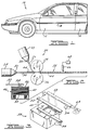
- FIG. 1 shows a side view of a vehicle 10 including a vehicle door 12.
- the trim strip 14 provides decoration to the vehicle 10, and also protects the paint finish of the vehicle door 12 and the side panel 16 against scratches, scrapes and dings resulting from contact with rigid objects, such as other vehicle doors, around the vehicle 10.
- the trim strip 14 includes intermittent sections of a bright strip or colored strip insert formed by an extrusion process according to the invention.
- FIG. 2 depicts an extrusion system 20 that is applicable to produce the trim strip 14.
- the extrusion system 20 includes a first extrusion die 22 and a second extrusion die 24.
- the first extrusion die emits a clear melt stream 26 of a suitable material, such as a thermoplastic material, from an orifice 28 of the die 22.
- the second extrusion die 24 emits a base melt stream 30 of a suitable material, such as a thermoplastic material, from an orifice 32 of the die 24.
- thermoplastic material that makes up the clear melt stream 26 and the base melt stream 30 can be any suitable material for the purposes described herein, such as a flexible polyvinylchloride, a thermoplastic olefin, a thermoplastic urethane, as well as other types of plastics.
- a flexible polyvinylchloride such as a thermoplastic olefin, a thermoplastic urethane, as well as other types of plastics.
- other materials are also adaptable to an extrusion process for trim strips associated with vehicles including, but not limited, certain rubbers, chrome, mylar, etc.
- the clear melt stream 26 will be significantly transparent or translucent, and the base melt stream 30 will be opaque.
- the melt streams 26 and 30 can be of any transparency depending on their material.
- the extrusion dies 22 and 24 are intended to represent known types of extrusion dies in the art where a powder, pellet or liquid thermoplastic material is heated to a pliable consistency, and forced out of the orifices 28 and 32 under a pressure to form the streams 26 and 30 to desirable heated plastic consistency.
- the extrusion dies 22 and 24 can be separate extrusion dies, or a split-stream extrusion die, where the dies 22 and 24 would be part of a single extrusion device, as is well understood in the art.
- a pair of cooperating forming rolls 34 and 36 receive the melt streams 26 and 30 to mold the melt streams 26 and 30 into a desirable shape as a continuous extrusion 38.
- the forming rolls 34 and 36 are driven in a synchronized relationship, and have a cooperating outer surface configuration which defines an opening (not shown) between the rolls 34 and 36 that forms the continuous extrusion 38 to its desired final cross-sectional configuration.
- the rolls 34 and 36 mold the heated and pliable melt streams 26 and 30 into the continuous extrusion 38 to have a desirable cross-sectional shape.
- the orifices 28 and 32 can have a shape that generally defines the cross-sectional shape of the melt streams 26 and 30 to be similar to that of the continuous extrusion 38.
- the continuous extrusion 38 is then subsequently cooled by a cooling apparatus (not shown).
- the material of the melt stream 26 provides a show surface of the continuous extrusion 38
- the material of the melt stream 30 forms a rigid support layer of the continuous extrusion 38 for a product such as the trim strip 14, as is well understood in the art.
- the melt streams 26 and 30 can be of the same material.
- a magazine 46 is provided for holding a stack 48 of a plurality of bright strip or colored strip sections that have been cut to a particular length for a particular trim strip application.
- the bright strip or colored strip sections 44 can be any colored thermoplastic material suitable for the extrusion process described herein, and desirable as an aesthetically pleasing strip for a trim strip member of a vehicle.
- the magazine 46 includes a spring loaded platform 50 that pushes the stack 48 of bright strip or colored strip sections 44 towards a top of the magazine 46 as bright strip sections 44 are removed from the magazine 46.
- a positioning device arm 52 having a suction head 54 presses down on the top of the stack 48 of sections 44 to remove a top section 56.
- the suction head 54 first lifts the top section 56 from the stack 48 out of the magazine 46, and then moves the top section 56 substantially directly towards the flow of the melt streams 26 and 30. Once the top section 56 has reached the melt streams 26 and 30, the positioning arm 52 then places the top section 56 between the melt streams 26 and 30, and moves the top section 56 in a direction substantially parallel to the flow of the melt streams 26 and 30.
- the top section 56 When an end of the top section 56 reaches the forming rolls 34 and 36 from the motion of the positioning arm 52, the top section 56 is grabbed by the forming rolls 34 and 36 and released by the suction head 52. Therefore, the sections 44 are molded between the melt streams 26 and 30 within the continuous extrusion 38, as shown.
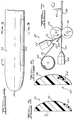
- Figure 3 shows a perspective view of a positioning device 58 including the arm 52.
- the arm 52 is shown at many locations to show the movement of the top section 56 from the magazine 46 to the cooperating rolls 34 and 36.
- the positioning am 52 first lifts the top section 56 from the magazine 46 in an upward direction as represented by arrow 60.
- the positioning arm 52 then moves the top section 56 in a direction substantially perpendicular to the flow of the melt streams 26 and 30 to position the top section 56 between the melt streams 26 and 30, as represented by arrow 62.
- the positioning arm 52 then moves the top section 56 in a direction parallel to the flow of the melt streams 26 and 30, as represented by arrow 64, such that the top section 56 is pushed into the forming rolls 34 and 36.
- the positioning arm 52 performs these steps at a fast enough pace such that the sections 44 are separated from each other by a desirable distance.
- the positioning arm 52 is controlled so that it places the sections 44 at a desirable location between the melt streams 26 and 30 for a particular application. It is stressed that the magazine 46 and the positioning device 58 are used by way of a non-limiting mechanism to insert the sections 44 between the melt streams 26 and 30.
- a cutter 66 positioned relative to the continuous extrusion 38, cuts the continuous extrusion 38 into desirable length pieces to form a plurality of extrusion strip sections.
- the cutter 66 is controlled by a suitable control device 68 so that the cutter 66 cuts sections from the continuous extrusion 38 at the desirable locations.
- the sections 44 may be of a short enough length such that a single trim strip could include a plurality of intermittent sections. Therefore, as will be appreciated by those skilled in the art, the cutter 66 can cut the continuous extrusion 38 at any desirable location for a desired trim strip product.
- Figure 4 shows a cut-away, top view of a trim strip product 72 separated from the extrusion 38.
- the strip products 72 has undergone subsequent end processing to form a tapered end 74.
- End processing of strip products cut from a continuous extrusion are well understood in the art.
- U.S. Patent No. 5,149,479 shows one end forming technique of an extruded strip product known in the art.
- Figure 5 shows a cross-sectional view along line 5-5 of the trim strip product 72.
- the trim strip product 72 includes a flat base layer 76 configured to lay flat against the vehicle 10, and an upper rounded layer 78 as a show surface.
- the flat base layer 76 is formed from the melt stream 30 and the rounded layer 78 is formed from the melt stream 26.
- a thin, narrow length of a bright strip section 80 extends along the side of the trim strip product 72 to provide a desirable appearance.
- the continuous extrusion 38 was cut between the sections 44 such that the end 74 does not include a strip section 44 that would interfere with the end forming process.
- FIG. 6 shows a cross-sectional view of a trim strip product 82 including a bright strip section 84, where the bright strip section 84 is at a different location within a top layer 86 than the bright strip section 80 of the strip product 72.
- FIG. 7 shows the system 20 in which the magazine 46 has been replaced with a strip roll 88 having a length of a rolled bright strip or colored strips 90.
- a cutter 92 cuts the strips 90 into precut sections 94 to be positioned between the melt streams 26 and 30 as they are introduced into the forming rolls 34 and 36.
Landscapes
- Engineering & Computer Science (AREA)
- Mechanical Engineering (AREA)
- Extrusion Moulding Of Plastics Or The Like (AREA)
- Vehicle Interior And Exterior Ornaments, Soundproofing, And Insulation (AREA)
Priority Applications (4)
| Application Number | Priority Date | Filing Date | Title |
|---|---|---|---|
| US08/591,313 US5772827A (en) | 1996-01-25 | 1996-01-25 | Trim member including intermittent bright strip and method of making same |
| JP9014742A JPH09201862A (ja) | 1996-01-25 | 1997-01-10 | 装飾帯片製品とその製造方法 |
| BR9700697A BR9700697A (pt) | 1996-01-25 | 1997-01-16 | Processo para a produçao de elementos de acabamento incluindo tira brilhante intermitente e respectivo produto resultante |
| EP97304276A EP0885777A1 (en) | 1996-01-25 | 1997-06-18 | Trim member including intermittent bright strip and method of making same |
Applications Claiming Priority (2)
| Application Number | Priority Date | Filing Date | Title |
|---|---|---|---|
| US08/591,313 US5772827A (en) | 1996-01-25 | 1996-01-25 | Trim member including intermittent bright strip and method of making same |
| EP97304276A EP0885777A1 (en) | 1996-01-25 | 1997-06-18 | Trim member including intermittent bright strip and method of making same |
Publications (1)
| Publication Number | Publication Date |
|---|---|
| EP0885777A1 true EP0885777A1 (en) | 1998-12-23 |
Family
ID=26147477
Family Applications (1)
| Application Number | Title | Priority Date | Filing Date |
|---|---|---|---|
| EP97304276A Withdrawn EP0885777A1 (en) | 1996-01-25 | 1997-06-18 | Trim member including intermittent bright strip and method of making same |
Country Status (4)
| Country | Link |
|---|---|
| US (1) | US5772827A (enExample) |
| EP (1) | EP0885777A1 (enExample) |
| JP (1) | JPH09201862A (enExample) |
| BR (1) | BR9700697A (enExample) |
Families Citing this family (13)
| Publication number | Priority date | Publication date | Assignee | Title |
|---|---|---|---|---|
| US5904884A (en) * | 1997-06-26 | 1999-05-18 | Decoma International Inc. | Method of forming automotive trim strip from extruded thermoplastic materials |
| US6187233B1 (en) * | 1998-12-15 | 2001-02-13 | Guardian Automotive Trim, Inc. | Automotive trim with clear top coat and method of making same |
| US6319438B1 (en) | 1998-12-15 | 2001-11-20 | Guardian Automotive Trim, Inc. | Extruded automotive trim and method of making same |
| US6248199B1 (en) * | 1999-04-26 | 2001-06-19 | Soundcraft, Inc. | Method for the continuous fabrication of access control and identification cards with embedded electronics or other elements |
| US7195727B2 (en) | 1999-10-13 | 2007-03-27 | Guardian Industries Corp. | Extruded automotive trim and method of making same |
| US6625949B2 (en) * | 2001-02-01 | 2003-09-30 | Guardian Industries Corp. | Method of manufacturing automotive trim using vibration welding, and resulting article |
| US6901641B2 (en) * | 2002-05-29 | 2005-06-07 | Isoteck Corporation | Method for manufacturing a valance having a ridge with an accent color |
| US20040200397A1 (en) * | 2003-01-23 | 2004-10-14 | Morse Industries, Inc. | Rubstrip coextrusion for vessels |
| US8158241B2 (en) * | 2003-03-04 | 2012-04-17 | Arkema France | Article displaying edgewise, angular multi-chromatic characteristics |
| CA2681088A1 (en) * | 2007-03-16 | 2008-09-25 | Magna International Inc. | Glass run with integrated upper reveal |
| US8820133B2 (en) * | 2008-02-01 | 2014-09-02 | Apple Inc. | Co-extruded materials and methods |
| US20130174492A1 (en) * | 2010-03-03 | 2013-07-11 | Cooper-Standard Automotive, Inc. | Co-extruded roll formed bright extrusion with integral end forms |
| GB201119539D0 (en) * | 2011-11-14 | 2011-12-21 | Defendoors Ltd | Method and apparatus for extrusion moulding |
Citations (3)
| Publication number | Priority date | Publication date | Assignee | Title |
|---|---|---|---|---|
| GB2080193A (en) * | 1980-07-17 | 1982-02-03 | Standard Products Co | Thermoplastic elastomer moulding |
| DE4416843A1 (de) * | 1994-05-13 | 1995-11-16 | Umformtechnisches Zentrum Gmbh | Zick-Zack-Vorschubeinrichtung |
| GB2306380A (en) * | 1995-10-18 | 1997-05-07 | Standard Products Co | Providing stabilized lengths of extruded strips |
Family Cites Families (11)
| Publication number | Priority date | Publication date | Assignee | Title |
|---|---|---|---|---|
| US3765817A (en) * | 1969-07-07 | 1973-10-16 | Union Carbide Corp | Apparatus for the calendering of polymeric materials |
| US3755052A (en) * | 1971-05-10 | 1973-08-28 | Protective Treatments | Decorative plastic trim strip |
| US4318764A (en) * | 1980-05-05 | 1982-03-09 | Voplex Corporation | Method of extrusion/injection molding of trimmed product |
| US4428156A (en) * | 1981-10-02 | 1984-01-31 | Mastic Corporation | Reinforced window assembly |
| US5023033A (en) * | 1989-08-24 | 1991-06-11 | Aeroquip Corporation | Decorative plastic trim strip and method and apparatus for forming |
| JPH0817113B2 (ja) * | 1991-03-13 | 1996-02-21 | ザ スタンダード プロダクツ カンパニー | エレクトロルミネッセントライトストリップ |
| US5409653A (en) * | 1991-11-05 | 1995-04-25 | The Standard Products Company | Method of forming strip products from theremoplastic materials |
| US5478516A (en) * | 1991-11-05 | 1995-12-26 | The Standard Products Company | Method of forming strip products from thermoplastic materials |
| US5171499A (en) * | 1991-11-05 | 1992-12-15 | The Standard Products Company | Method of forming strip products from thermoplastic materials |
| US5149478A (en) * | 1991-11-18 | 1992-09-22 | The Standard Products Company | Forming decorative trim strips from continuous extrusions |
| US5226998A (en) * | 1991-12-02 | 1993-07-13 | Plastic Trim, Inc. | Process for making a vehicle molding |
-
1996
- 1996-01-25 US US08/591,313 patent/US5772827A/en not_active Expired - Fee Related
-
1997
- 1997-01-10 JP JP9014742A patent/JPH09201862A/ja active Pending
- 1997-01-16 BR BR9700697A patent/BR9700697A/pt not_active Application Discontinuation
- 1997-06-18 EP EP97304276A patent/EP0885777A1/en not_active Withdrawn
Patent Citations (3)
| Publication number | Priority date | Publication date | Assignee | Title |
|---|---|---|---|---|
| GB2080193A (en) * | 1980-07-17 | 1982-02-03 | Standard Products Co | Thermoplastic elastomer moulding |
| DE4416843A1 (de) * | 1994-05-13 | 1995-11-16 | Umformtechnisches Zentrum Gmbh | Zick-Zack-Vorschubeinrichtung |
| GB2306380A (en) * | 1995-10-18 | 1997-05-07 | Standard Products Co | Providing stabilized lengths of extruded strips |
Also Published As
| Publication number | Publication date |
|---|---|
| US5772827A (en) | 1998-06-30 |
| JPH09201862A (ja) | 1997-08-05 |
| BR9700697A (pt) | 1998-08-18 |
Similar Documents
| Publication | Publication Date | Title |
|---|---|---|
| US5772827A (en) | Trim member including intermittent bright strip and method of making same | |
| CA2143507C (en) | Method of forming strip products from thermoplastic materials | |
| CA2076262C (en) | Method of forming strip products from thermoplastic materials | |
| CA2227822C (en) | Bodyside molding with bright insert and method of making same | |
| JPH02502555A (ja) | スティフナーを内蔵する押出しビニール成形体 | |
| US5226998A (en) | Process for making a vehicle molding | |
| EP0546660A1 (en) | Method of forming a decorative trim strip | |
| GB2310879A (en) | Recyclable vehicle pinch flange welt or door seal and method of making same | |
| GB2078620A (en) | Protective trim strip | |
| EP0282271B1 (en) | Decorative article and process for making the same | |
| US20050017404A1 (en) | Method of molding a vehicle trim component | |
| US5800657A (en) | Method of intermittent length stabilization | |
| AU734236B2 (en) | Method of forming automotive trim strip from extruded thermoplastic materials | |
| EP0497335A2 (en) | Method for the production of coated panels | |
| MXPA96004301A (en) | Method for stabilization of longitudintermite | |
| JPS63242526A (ja) | モ−ルデイングの製造方法 | |
| US5965083A (en) | Process of making B-pillar covers for automotive vehicle | |
| JP3144016B2 (ja) | トリム材の製造方法および装置 | |
| KR100589355B1 (ko) | 자동차용 몰딩 제조 방법 및 시스템 | |
| DE3844976C2 (de) | Kunststoffextrudat | |
| JP2748586B2 (ja) | カバーを有する長尺トリム材の製造方法 | |
| JP3104369B2 (ja) | トリム材の製造方法および装置 | |
| JP4660838B2 (ja) | トリム等の押出し成形品の成形方法 | |
| CA1278660C (en) | Method and apparatus for blow molding automotive component | |
| JPS621518A (ja) | 押出成形品の製造方法 |
Legal Events
| Date | Code | Title | Description |
|---|---|---|---|
| PUAI | Public reference made under article 153(3) epc to a published international application that has entered the european phase |
Free format text: ORIGINAL CODE: 0009012 |
|
| AK | Designated contracting states |
Kind code of ref document: A1 Designated state(s): AT BE CH DE DK ES FI FR GB GR IE IT LI LU MC NL PT SE |
|
| AX | Request for extension of the european patent |
Free format text: AL;LT;LV;RO;SI |
|
| 17P | Request for examination filed |
Effective date: 19990614 |
|
| AKX | Designation fees paid |
Free format text: AT BE CH DE DK ES FI FR GB GR IE IT LI LU MC NL PT SE |
|
| 17Q | First examination report despatched |
Effective date: 20000912 |
|
| RAP1 | Party data changed (applicant data changed or rights of an application transferred) |
Owner name: COOPER-STANDARD AUTOMOTIVE INC. |
|
| GRAP | Despatch of communication of intention to grant a patent |
Free format text: ORIGINAL CODE: EPIDOSNIGR1 |
|
| STAA | Information on the status of an ep patent application or granted ep patent |
Free format text: STATUS: THE APPLICATION IS DEEMED TO BE WITHDRAWN |
|
| 18D | Application deemed to be withdrawn |
Effective date: 20051116 |