EP0884693B1 - Procédé d'interpolation d'images binaires - Google Patents
Procédé d'interpolation d'images binaires Download PDFInfo
- Publication number
- EP0884693B1 EP0884693B1 EP97310482A EP97310482A EP0884693B1 EP 0884693 B1 EP0884693 B1 EP 0884693B1 EP 97310482 A EP97310482 A EP 97310482A EP 97310482 A EP97310482 A EP 97310482A EP 0884693 B1 EP0884693 B1 EP 0884693B1
- Authority
- EP
- European Patent Office
- Prior art keywords
- value
- interpolation
- pixel
- pixels
- binary image
- Prior art date
- Legal status (The legal status is an assumption and is not a legal conclusion. Google has not performed a legal analysis and makes no representation as to the accuracy of the status listed.)
- Expired - Lifetime
Links
Images


Classifications
-
- G—PHYSICS
- G06—COMPUTING; CALCULATING OR COUNTING
- G06T—IMAGE DATA PROCESSING OR GENERATION, IN GENERAL
- G06T3/00—Geometric image transformation in the plane of the image
- G06T3/40—Scaling the whole image or part thereof
-
- G—PHYSICS
- G06—COMPUTING; CALCULATING OR COUNTING
- G06T—IMAGE DATA PROCESSING OR GENERATION, IN GENERAL
- G06T3/00—Geometric image transformation in the plane of the image
- G06T3/40—Scaling the whole image or part thereof
- G06T3/4007—Interpolation-based scaling, e.g. bilinear interpolation
-
- H—ELECTRICITY
- H04—ELECTRIC COMMUNICATION TECHNIQUE
- H04N—PICTORIAL COMMUNICATION, e.g. TELEVISION
- H04N19/00—Methods or arrangements for coding, decoding, compressing or decompressing digital video signals
- H04N19/10—Methods or arrangements for coding, decoding, compressing or decompressing digital video signals using adaptive coding
- H04N19/102—Methods or arrangements for coding, decoding, compressing or decompressing digital video signals using adaptive coding characterised by the element, parameter or selection affected or controlled by the adaptive coding
- H04N19/13—Adaptive entropy coding, e.g. adaptive variable length coding [AVLC] or context adaptive binary arithmetic coding [CABAC]
Definitions
- the present invention relates to an interpolation method for a binary image, and more particularly, to an improved interpolation method in which a variable threshold value used for determining a pixel value to be generated by interpolation is determined according to a context (the state value of adjacent pixels).
- the shape information which refers to object information of the image, is expressed as a binary image.
- MPEG-4 adopts a content-based arithmetic encoder (CAE).
- CAE content-based arithmetic encoder
- For lossy shape coding a down sampling method and an upsampling method are performed in each shape macro block. A shape image is divided into shape blocks which have M ⁇ M block size.
- the down sampling refers to a method for reducing the binary image block according to a given conversion ratio.
- the reduced image block is transmitted together with the conversion ratio.
- the conversion ratio is determined such that an error between the original binary image block and an binary image block restored later is within a predetermined range.
- the reduced image block obtained by the down sampling is coded by a context based arithmetic encoder (CAE) and then transmitted.
- CAE context based arithmetic encoder
- the up sampling method is used to restore such a reduced image block.
- Up sampling is for restoring the reduced image block into the original binary image, by interpolation.
- an effective interpolation method must not cause excessive blocking and smoothing effects in the restored binary image.
- an interpolation method for a binary image for restoring a reduced binary image, reduced from an original binary image by down sampling, into the original binary image, the method comprising the steps of: (a) calculating an interpolation value based on the pixel values (object pixel values) of the reduced image around an interpolated pixel; (b) calculating a context C P (a state value of pixels (reference pixels) around the object pixels); (c) obtaining a threshold value corresponding to the calculated context; and (d) comparing the interpolation value with the threshold value of the step (c), and setting the pixel value of the interpolated pixel as "1" if the interpolation value is greater than the threshold value, and setting the pixel value of the interpolated pixel as "0" if the interpolation value is equal to or less than the threshold value.
- coding and decoding methods for a binary image having object information according to the MPEG-4 includes a down sampling step 100, a coding step 102, a reverse coding step 104 and an up sampling step 106.
- an M ⁇ N binary image block is converted into an (M ⁇ CR) ⁇ (N ⁇ CR) binary image block.
- CR is a conversion ratio indicating the ratio in size of the reduced image block obtained by the down sampling with respect to the original binary image block.
- the reduced image is encoded.
- MPEG-4 adopts a context based arithmetic encoder (CAE).
- CAE is an encoder which divides the binary image into blocks and processes all blocks by the same method.
- the CAE is adopted as a coding method in the verification model of MPEG-4, due to its simplicity and comparatively high coding efficiency.
- the reduced image coded through the coding step 102 is transmitted via a transmission route.
- the reverse coding step 104 the coded reduced image is restored into the reduced image.
- the up sampling step 106 the interpolation is performed on the reduced image to obtain the original binary image.
- the transmission route is a channel (e.g. radio or telephone link) interconnecting the coder (which may be a videophone incorporating a camera supplying the image) and the signal decoder (which may be videophone, further incorporating a VDU).
- the coder and decoder may be a computer and the transmission route a storage device (e.g. hard disc).
- the coder may include a local decoder at the same side of the transmission route, in order to provide a restored binary image for comparison with the original binary image without requiring transmission of the restored binary image over the transmission route.
- FIG. 1B illustrates in detail the down sampling step 100 shown in FIG. 1A.
- the binary image 200 is made into a plurality of macro blocks, as shown in FIG. 1B. Pixels indicated by a character "0" in a macro block 201 are converted into one pixel indicated by a character "X".
- the size of the macro block is determined depending on the conversion ratio.
- the conversion ratio of MPEG-4 may be 1, 1 ⁇ 2 or 1/4. Such conversion is performed on all macro blocks, resulting in an image reduced by the conversion ratio.
- four pixels (indicated by "0") of a macro block are reduced to a pixel, that is, the conversion ratio is equal to 1/2.
- pixels having value "1" represent a part of the picture containing an object
- pixels having value "0” represent a part of the picture without an object.
- the boundary between pixels having value "1” and pixels having value "0” represents the boundary of the object information.
- FIG. 1C illustrates in detail the up sampling step 106 shown in FIG. 1A.
- each pixel of the original binary image is restored by the interpolation using four pixels of the reduced image.
- pixels A, B, C and D represent object pixels, which are pixels concerned in the interpolation
- pixels P1, P2, P3 and P4 represent interpolated pixels, which are pixels to be obtained by the interpolation.
- the object pixels A, B, C and D surround the interpolated pixels P1, P2, P3 and P4.
- the object pixels belong to the reduced image while the interpolated pixels belong to the restored binary image.
- the obtained interpolation value INP[P] and a threshold value THR are compared.
- the threshold value THR is set to a value which is half of the largest possible interpolation value. If the interpolation value INP[P] is greater than the threshold value THR, the pixel value of that interpolated pixel becomes "1". Otherwise, the pixel value of the interpolated pixel becomes "0".
- a threshold value to be compared with the interpolation value INP[P] is adaptively determined according to the context (state values of the pixels (reference pixels) around the interpolated pixel), thereby reducing ambiguity in determination of the pixel value of the interpolated pixel. Also, proposed threshold values are determined using a learning method.
- pixels A, B, C, D, C0, C1, C2, C3 and C4 indicated by “0” are pixels of the reduced image
- pixels P1, P2, P3 and P4 indicated by "X” represent the interpolated pixels of the restored binary image.
- the interpolation value of a pixel to be generated by the interpolation is calculated.
- the interpolation value is calculated by a bilinear interpolation method.
- the interpolation value may alternatively be calculated by using the average of the object pixels or other methods.
- the interpolation value INP[P] is determined as a value between 0 and 1.
- the number of combinations of the object pixels is equal to 16, and the number of interpolation values INP[P] is 16. However, if duplicate values are not counted, the actual number of interpolation values is 12, which are all between 0 and 1. Accordingly, an integer t has the range of 0 ⁇ 11, and the number of proposed threshold values THRc[t] is equal to 12, including 0, 0.0625, 0.1875, 0.25, 0.375, 0.4375, 0.5625, 0.625, 0.75, 0.8125, 0.9375 and 1.
- the context (state value of the reference pixels) is calculated by the following equation (2): where P represents the position of the interpolated pixel, R represents the reference pixel, and k is an index of reference pixels and also a weight.
- the index k is varied depending on the position of the interpolated pixel.
- five pixels around the object pixels are used as the reference pixels.
- FIGs. 2A through 2D show positions and indices of the reference pixels used for interpolating the interpolated pixels P1 through P4, respectively.
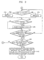
- the proposed threshold values THRc[t] are determined by a learning method, described below.
- the interpolation value INP[P] and the threshold value THRc based on the context are compared to determine the pixel value of the interpolated pixel.
- the pixel value of the interpolated pixel becomes "1". Otherwise, the pixel value of the interpolated pixel becomes "0".
- the threshold value THRc is obtained by the learning method.
- the learning is performed by the step of comparing the original binary image with the restored binary image.
- arrays h[c][t] and THRc[t] are defined (step 310).
- the array h[c][t] holds numbers of hits, where a hit is the name given to when the restored pixel value is equal to the original pixel value.
- the hits are determined by applying all of the possible threshold values to each context.
- c is an index of the interpolation values
- t is an index of the proposed threshold values. In the case of FIG. 2, since the number of interpolation values and the number of proposed threshold values are both equal to 12, the size of the array becomes h[11][11].
- the array THRc[t] stores the proposed threshold values.
- t is an index of the proposed threshold values.
- the array h[c][t] is initialized to zero (step 320).
- the original binary image and the reduced image are input (step 330).
- the location of an initial interpolated pixel is determined.
- the interpolation is performed from the upper-left to the lower-right by a raster scanning (step 340).
- the threshold index t is initialized (step 355).
- the interpolation value INP[P] of the interpolated pixel is calculated (step 360).
- the current proposed threshold value from THRc[t] is compared with the calculated interpolation value INP[P] (step 370). If the interpolation value INP[P] is greater than the proposed threshold value THRc[t], the pixel value P of the interpolated pixel is set to "1" (step 372). Otherwise, the pixel value P of the interpolated pixel is set to "0" (step 374).
- the pixel value P of the interpolated pixel is compared with the original pixel value (step 380). If the pixel value P is equal to the original pixel value, the corresponding value in the array h[c][t] is increased by "1". This value represents the number of hits (step 385). Otherwise, the step 385 is not performed.
- step 390 It is checked whether the comparison of step 380 has been performed on all proposed threshold values of the current interpolation value.
- step 390 it is determined whether the interpolation has been performed on all pixels of the binary image (step 400).
- step 390 If the condition of step 390 is not satisfied, then the process returns to step 370.
- the proposed threshold value providing the highest frequency of hits is set as the threshold value of the corresponding interpolation value (step 400).
- step 390 If the condition of step 390 is not satisfied, the process returns to step 350.
- ambiguity of the restoration performed by using only the interpolation value obtained by the bilinear interpolation can be removed by using the context, thereby reducing restoration error in the restored binary image.
- FIGs. 4A through 4C show the effect of the interpolation method according to the present invention, in contrast to the conventional method.
- FIG. 4A shows the original binary image containing the MPEG-4 logo
- FIG. 4B shows the result of the conventional interpolation described with reference to FIG. 1C
- FIG. 4C shows the result of the interpolation according to the present invention.
- the blocking and smoothing effects are sharply reduced compared to the conventional method.
- the ambiguity in the comparison between the interpolation value and the threshold value is removed by using the context (state value of the reference pixels around the interpolated pixel), thereby reducing the blocking and smoothing phenomena in the restored binary image.
Claims (9)
- Procédé d'interpolation pour une image binaire réduite à partir d'une image binaire originale par échantillonnage à diminution, le procédé comprenant les étapes suivantes :(a) le calcul d'une valeur d'interpolation en fonction des valeurs de pixels (pixels d'objet) autour d'un pixel interpolé ;(b) le calcul d'un contexte Cp (une valeur d'état de pixels (pixels de référence) autour des pixels d'objet+ ;(c) l'obtention d'une valeur de seuil correspondant au contexte calculé ; et(d) la comparaison de la valeur d'interpolation à la valeur de seuil de l'étape (c), et l'établissement de la valeur de pixel du pixel interpolé à "1" si la valeur d'interpolation est supérieure à la valeur de seuil, et l'établissement de la valeur de pixel du pixel interpolé à "0" si la valeur d'interpolation est inférieure ou égale à la valeur de seuil.
- Procédé d'interpolation selon la revendication 1, dans lequel dans l'étape (a) est calculée à l'aide d'un procédé d'interpolation bilinéaire.
- Procédé d'interpolation selon la revendication 1, dans lequel l'étape (b) est effectuée en utilisant l'équation qui suit :où P représente la position du pixel interpolé, R représente le pixel de référence, et k est un indice du pixel de référence.

- Procédé d'interpolation selon la revendication 1, dans lequel la valeur de seuil obtenue dans l'étape (c) est l'une d'un certain nombre de valeurs de seuil proposées.
- Procédé selon la revendication 4, dans lequel le nombre est égal au nombre de valeurs d'interpolation obtenues en considérant toutes les permutations possibles des pixels d'objet.
- Procédé d'interpolation selon la revendication 4, dans lequel les valeurs de seuil proposées sont obtenues à l'aide des étapes suivantes :(a1) la définition de groupements h[c][t] et THRc[t], où c est un indice des valeurs d'interpolation, et t est un indice des valeurs de seuil proposées ;(a2) l'initialisation du groupement h[c][t] à zéro, et la réception de l'image binaire originale et de l'image réduite ;(a3) la détermination de l'emplacement du pixel interpolé devant être interpolé, selon un balayage de trame, et le calcul d'un contexte de pixels de référence ;(a4) l'initialisation de l'indice de seuil t ;(a5) le calcul de la valeur d'interpolation INP[P] du pixel interpolé ;(a6) la comparaison de la valeur de seuil proposée actuelle THRc[t] à la valeur d'interpolation calculée INP[P], et l'établissement de la valeur de pixel du pixel interpolé à "1" si la valeur d'interpolation INP[P] est supérieure à la valeur de seuil proposée THRc[t], et l'établissement de la valeur de pixel du pixel interpolé à "0" si la valeur d'interpolation INP[P] est inférieure ou égale à la valeur de seuil proposée THRc[t] ;(a7) la comparaison de la valeur de pixel du pixel interpolé à la valeur de pixel originale, et l'augmentation de la valeur du groupement h[c][t] et de l'indice de seuil t de "1" s'il y a une concordance, une concordance étant le cas dans lequel la valeur de pixel du pixel interpolé est égale à la valeur de pixel originale ;(a8) la vérification du fait que oui ou non la comparaison de l'étape a6 a été effectuée sur toutes les valeurs de seuil proposées, et le retour à l'étape a6 si la comparaison n'a pas été effectuée sur toutes les valeurs de seuil proposées ;(a9) la vérification du fait que oui ou non l'interpolation a été effectuée sur tous les pixels de l'image binaire, si la comparaison de l'étape a6 a été effectuée sur toutes les valeurs de seuil proposées, et le retour à l'étape a3 si l'interpolation n'a pas été effectuée sur tous les pixels de l'image binaire ; et(a10) l'établissement de la valeur de seuil proposée donnant la fréquence la plus élevée de concordances comme valeur de seuil de la valeur d'interpolation correspondante, si l'interpolation est effectuée sur tous les pixels de l'image binaire.
- Procédé de génération d'une image échantillonnée par diminution à partir d'une image originale par interpolation selon la revendication 1, et établissement de seuil ultérieur, comprenant la sélection du seuil parmi une pluralité de valeurs de seuil possibles de façon à réduire la divergence entre l'image originale et l'image reconstituée à partir de l'image échantillonnée par diminution.
- Codeur d'image configuré de façon à exécuter le procédé selon l'une quelconque des revendications précédentes.
- Codeur selon la revendication 8, configuré de façon à traiter une séquence d'images afin de produire une séquence vidéo codée.
Applications Claiming Priority (2)
| Application Number | Priority Date | Filing Date | Title |
|---|---|---|---|
| KR1019970021781A KR100314098B1 (ko) | 1997-05-29 | 1997-05-29 | 주위화소값의적응임계치를이용한이진영상보간방법 |
| KR9721781 | 1997-05-29 |
Publications (3)
| Publication Number | Publication Date |
|---|---|
| EP0884693A2 EP0884693A2 (fr) | 1998-12-16 |
| EP0884693A3 EP0884693A3 (fr) | 1999-10-20 |
| EP0884693B1 true EP0884693B1 (fr) | 2003-03-26 |
Family
ID=19507784
Family Applications (1)
| Application Number | Title | Priority Date | Filing Date |
|---|---|---|---|
| EP97310482A Expired - Lifetime EP0884693B1 (fr) | 1997-05-29 | 1997-12-23 | Procédé d'interpolation d'images binaires |
Country Status (11)
| Country | Link |
|---|---|
| US (3) | US6021230A (fr) |
| EP (1) | EP0884693B1 (fr) |
| JP (1) | JP3669833B2 (fr) |
| KR (1) | KR100314098B1 (fr) |
| CN (1) | CN1155258C (fr) |
| BR (1) | BR9705837B1 (fr) |
| DE (1) | DE69720198T2 (fr) |
| ID (1) | ID20379A (fr) |
| IL (1) | IL122771A (fr) |
| MY (1) | MY116137A (fr) |
| RU (1) | RU2221274C2 (fr) |
Families Citing this family (13)
| Publication number | Priority date | Publication date | Assignee | Title |
|---|---|---|---|---|
| JP3349957B2 (ja) * | 1997-07-09 | 2002-11-25 | 株式会社ハイニックスセミコンダクター | コンテキスト確率表を利用した二進映像情報の内挿装置および方法 |
| US6002812A (en) * | 1997-07-10 | 1999-12-14 | Samsung Electronics Co., Ltd. | Interpolation method for binary image |
| JP3212917B2 (ja) * | 1997-08-26 | 2001-09-25 | エヌイーシービューテクノロジー株式会社 | 走査線補間装置および走査線補間方法 |
| US6553153B1 (en) * | 1998-12-03 | 2003-04-22 | Chips And Technologies, Llc. | Method and apparatus for reducing video data |
| KR100486700B1 (ko) * | 1999-09-04 | 2005-05-03 | 삼성전자주식회사 | 선형 다운/업 샘플링 장치 및 그를 이용한 일반화된 격주사선 처리 부호화/복호화 방법 및 장치 |
| US6614917B1 (en) * | 1999-10-22 | 2003-09-02 | Lockheed Martin Corporation | Dynamic process for identifying objects in multi-dimensional data |
| WO2003052660A1 (fr) | 2001-12-17 | 2003-06-26 | Corning Incorporated | Systeme de selection de bobines de fibres optiques provenant d'un inventaire pour l'execution d'une commande |
| US7171493B2 (en) * | 2001-12-19 | 2007-01-30 | The Charles Stark Draper Laboratory | Camouflage of network traffic to resist attack |
| KR100467582B1 (ko) * | 2002-01-22 | 2005-01-24 | 삼성전자주식회사 | 이치화를 위한 어드레싱 방법 및 장치 |
| JP3767513B2 (ja) * | 2002-04-26 | 2006-04-19 | 三菱電機株式会社 | 画素補間回路、走査線補間回路、画素補間方法、走査線補間方法、および応用装置 |
| CN100452909C (zh) * | 2004-02-17 | 2009-01-14 | 英业达股份有限公司 | 一种无线局域网络环境检测系统及其方法 |
| CN1333372C (zh) * | 2006-03-30 | 2007-08-22 | 北京中星微电子有限公司 | 一种数字信号的重采样方法 |
| US20070247476A1 (en) * | 2006-04-21 | 2007-10-25 | Liron Yatziv | Fast smooth up-sampling of binary volumes derived from medical imaging |
Family Cites Families (19)
| Publication number | Priority date | Publication date | Assignee | Title |
|---|---|---|---|---|
| JPS55602A (en) * | 1978-03-22 | 1980-01-07 | Ricoh Co Ltd | Predictive restoration method for high-density picture element |
| JPS5676683A (en) * | 1979-11-28 | 1981-06-24 | Ricoh Co Ltd | Processing method for picture deformation |
| US4578812A (en) * | 1982-12-01 | 1986-03-25 | Nec Corporation | Digital image processing by hardware using cubic convolution interpolation |
| JPS61203785A (ja) * | 1985-03-07 | 1986-09-09 | Dainippon Screen Mfg Co Ltd | 2値画像デ−タの平滑化処理方法及びその装置 |
| EP0392701B1 (fr) * | 1989-04-10 | 1995-11-08 | Canon Kabushiki Kaisha | Dispositif pour la réduction d'images |
| US5121447A (en) * | 1989-04-27 | 1992-06-09 | Canon Kabushiki Kaisha | Apparatus for performing gradation processing on image data |
| US5054100A (en) * | 1989-11-16 | 1991-10-01 | Eastman Kodak Company | Pixel interpolator with edge sharpening |
| US5703965A (en) * | 1992-06-05 | 1997-12-30 | The Regents Of The University Of California | Image compression/decompression based on mathematical transform, reduction/expansion, and image sharpening |
| JP2967014B2 (ja) * | 1993-05-24 | 1999-10-25 | キヤノン株式会社 | 画像処理装置 |
| JPH0750752A (ja) * | 1993-08-06 | 1995-02-21 | Fuji Xerox Co Ltd | 画像密度変換方法及び装置 |
| EP0645736B1 (fr) * | 1993-09-27 | 2003-02-05 | Canon Kabushiki Kaisha | Appareil de traitement d'images |
| JP3195142B2 (ja) * | 1993-10-29 | 2001-08-06 | キヤノン株式会社 | 画像処理方法及び装置 |
| US5644661A (en) * | 1993-10-29 | 1997-07-01 | British Technology Group Limited | Image interpolator for an image display system |
| JPH08186714A (ja) * | 1994-12-27 | 1996-07-16 | Texas Instr Inc <Ti> | 画像データのノイズ除去方法及びその装置 |
| KR0176765B1 (ko) | 1995-01-25 | 1999-05-01 | 구자홍 | 화상의 방향성 보간방법 |
| JPH09149241A (ja) * | 1995-11-24 | 1997-06-06 | Kokusai Electric Co Ltd | 画像拡大方法及び画像拡大装置 |
| FR2743241B1 (fr) * | 1995-12-28 | 1998-02-13 | Sagem | Procede de modification de la resolution d'une image numerisee |
| US5638187A (en) * | 1996-02-23 | 1997-06-10 | Hewlett-Packard Company | Image dithering method enabling conversion of a gray level pixel image into a binary pixel image |
| US5832134A (en) * | 1996-11-27 | 1998-11-03 | General Electric Company | Data visualization enhancement through removal of dominating structures |
-
1997
- 1997-05-29 KR KR1019970021781A patent/KR100314098B1/ko active IP Right Grant
- 1997-11-26 US US08/979,852 patent/US6021230A/en not_active Ceased
- 1997-12-23 ID IDP973961A patent/ID20379A/id unknown
- 1997-12-23 DE DE69720198T patent/DE69720198T2/de not_active Expired - Lifetime
- 1997-12-23 EP EP97310482A patent/EP0884693B1/fr not_active Expired - Lifetime
- 1997-12-25 IL IL12277197A patent/IL122771A/xx not_active IP Right Cessation
- 1997-12-29 MY MYPI97006401A patent/MY116137A/en unknown
- 1997-12-29 BR BRPI9705837-8B1A patent/BR9705837B1/pt not_active IP Right Cessation
- 1997-12-29 CN CNB971234671A patent/CN1155258C/zh not_active Expired - Lifetime
- 1997-12-30 RU RU97121882/09A patent/RU2221274C2/ru active
-
1998
- 1998-02-26 JP JP04587798A patent/JP3669833B2/ja not_active Expired - Lifetime
- 1998-05-29 US US09/087,270 patent/US6018601A/en not_active Ceased
-
2000
- 2000-07-31 US US09/630,286 patent/USRE37792E1/en not_active Expired - Lifetime
Also Published As
| Publication number | Publication date |
|---|---|
| CN1155258C (zh) | 2004-06-23 |
| EP0884693A3 (fr) | 1999-10-20 |
| JPH10336431A (ja) | 1998-12-18 |
| BR9705837B1 (pt) | 2013-06-11 |
| US6021230A (en) | 2000-02-01 |
| DE69720198D1 (de) | 2003-04-30 |
| DE69720198T2 (de) | 2004-01-29 |
| CN1201333A (zh) | 1998-12-09 |
| US6018601A (en) | 2000-01-25 |
| MY116137A (en) | 2003-11-28 |
| JP3669833B2 (ja) | 2005-07-13 |
| USRE37792E1 (en) | 2002-07-16 |
| KR19980085643A (ko) | 1998-12-05 |
| ID20379A (id) | 1998-12-03 |
| BR9705837A (pt) | 1999-03-16 |
| IL122771A0 (en) | 1998-08-16 |
| RU2221274C2 (ru) | 2004-01-10 |
| KR100314098B1 (ko) | 2001-12-12 |
| EP0884693A2 (fr) | 1998-12-16 |
| IL122771A (en) | 2003-06-24 |
Similar Documents
| Publication | Publication Date | Title |
|---|---|---|
| EP0705035B1 (fr) | Codage de données représentées par un réseau multi-dimensionnel | |
| US5305400A (en) | Method of encoding and decoding the video data of an image sequence | |
| EP0630157B1 (fr) | Systèmes et méthodes pour le codage de trames alternées de séquences vidéo entrelacées | |
| US6621864B1 (en) | Motion vector based frame insertion process for increasing the frame rate of moving images | |
| EP0884693B1 (fr) | Procédé d'interpolation d'images binaires | |
| US20090304090A1 (en) | Method for Scalable Video Coding | |
| US20070047651A1 (en) | Video prediction apparatus and method for multi-format codec and video encoding/decoding apparatus and method using the video prediction apparatus and method | |
| JP3659157B2 (ja) | 映像内容に重み付けをする画像圧縮方式 | |
| EP0721284B1 (fr) | Système de traitement d'images utilisant une estimation du mouvement pixel à pixel et un décimation d'images | |
| EP0890921B1 (fr) | Procédé d'interpolation d'images binaires | |
| US5717465A (en) | Apparatus for coding an object region of a video signal by using a rearranged block-based coding technique | |
| EP0806742B1 (fr) | Codage de contour adaptatif | |
| Yeh et al. | Motion compensation of motion vectors | |
| US6545727B1 (en) | Method for recognizing a progressive or an interlaced content in a video sequence | |
| CN1078795C (zh) | 用在图象编码系统中的改进的运动补偿方法 | |
| EP1198139A1 (fr) | Procédé et dispositif de codage de trames vidéo | |
| NL1008938C2 (nl) | Scan-verschervingswerkwijze. | |
| FR2769784A1 (fr) | Methode de codage de mode dans un codage de forme binaire | |
| US5760845A (en) | Method for determining motion vectors based on a block matching motion estimation technique | |
| Hadar et al. | New hybrid error concealment for digital compressed video | |
| US5095366A (en) | Video signal coding device and decoding device utilizing plural quantization/inverse quantization | |
| Sanderson et al. | Image segmentation for compression of images and image sequences | |
| EP0923250A1 (fr) | Méthode et dispositif de codage adaptatif d'un signal binaire de contour | |
| Limb | Picture coding: The use of a viewer model in source encoding | |
| JP3265287B2 (ja) | 画像データの高能率符号化方法およびその装置 |
Legal Events
| Date | Code | Title | Description |
|---|---|---|---|
| PUAI | Public reference made under article 153(3) epc to a published international application that has entered the european phase |
Free format text: ORIGINAL CODE: 0009012 |
|
| AK | Designated contracting states |
Kind code of ref document: A2 Designated state(s): DE FR GB NL |
|
| AX | Request for extension of the european patent |
Free format text: AL;LT;LV;MK;RO;SI |
|
| PUAL | Search report despatched |
Free format text: ORIGINAL CODE: 0009013 |
|
| AK | Designated contracting states |
Kind code of ref document: A3 Designated state(s): AT BE CH DE DK ES FI FR GB GR IE IT LI LU MC NL PT SE |
|
| AX | Request for extension of the european patent |
Free format text: AL;LT;LV;MK;RO;SI |
|
| 17P | Request for examination filed |
Effective date: 20000407 |
|
| AKX | Designation fees paid |
Free format text: DE FR GB NL |
|
| GRAH | Despatch of communication of intention to grant a patent |
Free format text: ORIGINAL CODE: EPIDOS IGRA |
|
| GRAH | Despatch of communication of intention to grant a patent |
Free format text: ORIGINAL CODE: EPIDOS IGRA |
|
| GRAA | (expected) grant |
Free format text: ORIGINAL CODE: 0009210 |
|
| AK | Designated contracting states |
Designated state(s): DE FR GB NL |
|
| REG | Reference to a national code |
Ref country code: GB Ref legal event code: FG4D |
|
| REF | Corresponds to: |
Ref document number: 69720198 Country of ref document: DE Date of ref document: 20030430 Kind code of ref document: P |
|
| ET | Fr: translation filed | ||
| PLBE | No opposition filed within time limit |
Free format text: ORIGINAL CODE: 0009261 |
|
| STAA | Information on the status of an ep patent application or granted ep patent |
Free format text: STATUS: NO OPPOSITION FILED WITHIN TIME LIMIT |
|
| 26N | No opposition filed |
Effective date: 20031230 |
|
| REG | Reference to a national code |
Ref country code: FR Ref legal event code: PLFP Year of fee payment: 19 |
|
| REG | Reference to a national code |
Ref country code: FR Ref legal event code: PLFP Year of fee payment: 20 |
|
| PGFP | Annual fee paid to national office [announced via postgrant information from national office to epo] |
Ref country code: DE Payment date: 20161122 Year of fee payment: 20 Ref country code: NL Payment date: 20161121 Year of fee payment: 20 Ref country code: GB Payment date: 20161122 Year of fee payment: 20 Ref country code: FR Payment date: 20161124 Year of fee payment: 20 |
|
| REG | Reference to a national code |
Ref country code: DE Ref legal event code: R071 Ref document number: 69720198 Country of ref document: DE |
|
| REG | Reference to a national code |
Ref country code: NL Ref legal event code: MK Effective date: 20171222 |
|
| REG | Reference to a national code |
Ref country code: GB Ref legal event code: PE20 Expiry date: 20171222 |
|
| PG25 | Lapsed in a contracting state [announced via postgrant information from national office to epo] |
Ref country code: GB Free format text: LAPSE BECAUSE OF EXPIRATION OF PROTECTION Effective date: 20171222 |