EP0884500A2 - Dämpfventil mit einstellbarer Dämpfkraft - Google Patents
Dämpfventil mit einstellbarer Dämpfkraft Download PDFInfo
- Publication number
- EP0884500A2 EP0884500A2 EP98107379A EP98107379A EP0884500A2 EP 0884500 A2 EP0884500 A2 EP 0884500A2 EP 98107379 A EP98107379 A EP 98107379A EP 98107379 A EP98107379 A EP 98107379A EP 0884500 A2 EP0884500 A2 EP 0884500A2
- Authority
- EP
- European Patent Office
- Prior art keywords
- sleeve
- valve
- spring
- damping valve
- damping
- Prior art date
- Legal status (The legal status is an assumption and is not a legal conclusion. Google has not performed a legal analysis and makes no representation as to the accuracy of the status listed.)
- Granted
Links
- 238000013016 damping Methods 0.000 title claims abstract description 48
- 230000036316 preload Effects 0.000 claims abstract description 5
- 230000005540 biological transmission Effects 0.000 claims abstract 2
- 238000006073 displacement reaction Methods 0.000 abstract description 2
- 238000009434 installation Methods 0.000 description 2
- 238000010276 construction Methods 0.000 description 1
- 210000003746 feather Anatomy 0.000 description 1
- 238000004519 manufacturing process Methods 0.000 description 1
- 230000004048 modification Effects 0.000 description 1
- 238000012986 modification Methods 0.000 description 1
- 238000005096 rolling process Methods 0.000 description 1
Images


Classifications
-
- F—MECHANICAL ENGINEERING; LIGHTING; HEATING; WEAPONS; BLASTING
- F16—ENGINEERING ELEMENTS AND UNITS; GENERAL MEASURES FOR PRODUCING AND MAINTAINING EFFECTIVE FUNCTIONING OF MACHINES OR INSTALLATIONS; THERMAL INSULATION IN GENERAL
- F16F—SPRINGS; SHOCK-ABSORBERS; MEANS FOR DAMPING VIBRATION
- F16F9/00—Springs, vibration-dampers, shock-absorbers, or similarly-constructed movement-dampers using a fluid or the equivalent as damping medium
- F16F9/32—Details
- F16F9/3207—Constructional features
- F16F9/3235—Constructional features of cylinders
- F16F9/325—Constructional features of cylinders for attachment of valve units
-
- F—MECHANICAL ENGINEERING; LIGHTING; HEATING; WEAPONS; BLASTING
- F16—ENGINEERING ELEMENTS AND UNITS; GENERAL MEASURES FOR PRODUCING AND MAINTAINING EFFECTIVE FUNCTIONING OF MACHINES OR INSTALLATIONS; THERMAL INSULATION IN GENERAL
- F16F—SPRINGS; SHOCK-ABSORBERS; MEANS FOR DAMPING VIBRATION
- F16F9/00—Springs, vibration-dampers, shock-absorbers, or similarly-constructed movement-dampers using a fluid or the equivalent as damping medium
- F16F9/32—Details
- F16F9/34—Special valve constructions; Shape or construction of throttling passages
-
- F—MECHANICAL ENGINEERING; LIGHTING; HEATING; WEAPONS; BLASTING
- F16—ENGINEERING ELEMENTS AND UNITS; GENERAL MEASURES FOR PRODUCING AND MAINTAINING EFFECTIVE FUNCTIONING OF MACHINES OR INSTALLATIONS; THERMAL INSULATION IN GENERAL
- F16F—SPRINGS; SHOCK-ABSORBERS; MEANS FOR DAMPING VIBRATION
- F16F9/00—Springs, vibration-dampers, shock-absorbers, or similarly-constructed movement-dampers using a fluid or the equivalent as damping medium
- F16F9/32—Details
- F16F9/44—Means on or in the damper for manual or non-automatic adjustment; such means combined with temperature correction
-
- F—MECHANICAL ENGINEERING; LIGHTING; HEATING; WEAPONS; BLASTING
- F16—ENGINEERING ELEMENTS AND UNITS; GENERAL MEASURES FOR PRODUCING AND MAINTAINING EFFECTIVE FUNCTIONING OF MACHINES OR INSTALLATIONS; THERMAL INSULATION IN GENERAL
- F16F—SPRINGS; SHOCK-ABSORBERS; MEANS FOR DAMPING VIBRATION
- F16F9/00—Springs, vibration-dampers, shock-absorbers, or similarly-constructed movement-dampers using a fluid or the equivalent as damping medium
- F16F9/32—Details
- F16F9/44—Means on or in the damper for manual or non-automatic adjustment; such means combined with temperature correction
- F16F9/46—Means on or in the damper for manual or non-automatic adjustment; such means combined with temperature correction allowing control from a distance, i.e. location of means for control input being remote from site of valves, e.g. on damper external wall
- F16F9/466—Throttling control, i.e. regulation of flow passage geometry
-
- F—MECHANICAL ENGINEERING; LIGHTING; HEATING; WEAPONS; BLASTING
- F16—ENGINEERING ELEMENTS AND UNITS; GENERAL MEASURES FOR PRODUCING AND MAINTAINING EFFECTIVE FUNCTIONING OF MACHINES OR INSTALLATIONS; THERMAL INSULATION IN GENERAL
- F16K—VALVES; TAPS; COCKS; ACTUATING-FLOATS; DEVICES FOR VENTING OR AERATING
- F16K15/00—Check valves
- F16K15/02—Check valves with guided rigid valve members
- F16K15/04—Check valves with guided rigid valve members shaped as balls
- F16K15/042—Check valves with guided rigid valve members shaped as balls with a plurality of balls
-
- F—MECHANICAL ENGINEERING; LIGHTING; HEATING; WEAPONS; BLASTING
- F16—ENGINEERING ELEMENTS AND UNITS; GENERAL MEASURES FOR PRODUCING AND MAINTAINING EFFECTIVE FUNCTIONING OF MACHINES OR INSTALLATIONS; THERMAL INSULATION IN GENERAL
- F16K—VALVES; TAPS; COCKS; ACTUATING-FLOATS; DEVICES FOR VENTING OR AERATING
- F16K15/00—Check valves
- F16K15/02—Check valves with guided rigid valve members
- F16K15/04—Check valves with guided rigid valve members shaped as balls
- F16K15/044—Check valves with guided rigid valve members shaped as balls spring-loaded
-
- F—MECHANICAL ENGINEERING; LIGHTING; HEATING; WEAPONS; BLASTING
- F16—ENGINEERING ELEMENTS AND UNITS; GENERAL MEASURES FOR PRODUCING AND MAINTAINING EFFECTIVE FUNCTIONING OF MACHINES OR INSTALLATIONS; THERMAL INSULATION IN GENERAL
- F16F—SPRINGS; SHOCK-ABSORBERS; MEANS FOR DAMPING VIBRATION
- F16F2230/00—Purpose; Design features
- F16F2230/36—Holes, slots or the like
-
- Y—GENERAL TAGGING OF NEW TECHNOLOGICAL DEVELOPMENTS; GENERAL TAGGING OF CROSS-SECTIONAL TECHNOLOGIES SPANNING OVER SEVERAL SECTIONS OF THE IPC; TECHNICAL SUBJECTS COVERED BY FORMER USPC CROSS-REFERENCE ART COLLECTIONS [XRACs] AND DIGESTS
- Y10—TECHNICAL SUBJECTS COVERED BY FORMER USPC
- Y10T—TECHNICAL SUBJECTS COVERED BY FORMER US CLASSIFICATION
- Y10T137/00—Fluid handling
- Y10T137/7722—Line condition change responsive valves
- Y10T137/7837—Direct response valves [i.e., check valve type]
- Y10T137/7838—Plural
- Y10T137/7839—Dividing and recombining in a single flow path
-
- Y—GENERAL TAGGING OF NEW TECHNOLOGICAL DEVELOPMENTS; GENERAL TAGGING OF CROSS-SECTIONAL TECHNOLOGIES SPANNING OVER SEVERAL SECTIONS OF THE IPC; TECHNICAL SUBJECTS COVERED BY FORMER USPC CROSS-REFERENCE ART COLLECTIONS [XRACs] AND DIGESTS
- Y10—TECHNICAL SUBJECTS COVERED BY FORMER USPC
- Y10T—TECHNICAL SUBJECTS COVERED BY FORMER US CLASSIFICATION
- Y10T137/00—Fluid handling
- Y10T137/7722—Line condition change responsive valves
- Y10T137/7837—Direct response valves [i.e., check valve type]
- Y10T137/7904—Reciprocating valves
- Y10T137/7922—Spring biased
- Y10T137/7927—Ball valves
-
- Y—GENERAL TAGGING OF NEW TECHNOLOGICAL DEVELOPMENTS; GENERAL TAGGING OF CROSS-SECTIONAL TECHNOLOGIES SPANNING OVER SEVERAL SECTIONS OF THE IPC; TECHNICAL SUBJECTS COVERED BY FORMER USPC CROSS-REFERENCE ART COLLECTIONS [XRACs] AND DIGESTS
- Y10—TECHNICAL SUBJECTS COVERED BY FORMER USPC
- Y10T—TECHNICAL SUBJECTS COVERED BY FORMER US CLASSIFICATION
- Y10T137/00—Fluid handling
- Y10T137/7722—Line condition change responsive valves
- Y10T137/7837—Direct response valves [i.e., check valve type]
- Y10T137/7904—Reciprocating valves
- Y10T137/7922—Spring biased
- Y10T137/7929—Spring coaxial with valve
-
- Y—GENERAL TAGGING OF NEW TECHNOLOGICAL DEVELOPMENTS; GENERAL TAGGING OF CROSS-SECTIONAL TECHNOLOGIES SPANNING OVER SEVERAL SECTIONS OF THE IPC; TECHNICAL SUBJECTS COVERED BY FORMER USPC CROSS-REFERENCE ART COLLECTIONS [XRACs] AND DIGESTS
- Y10—TECHNICAL SUBJECTS COVERED BY FORMER USPC
- Y10T—TECHNICAL SUBJECTS COVERED BY FORMER US CLASSIFICATION
- Y10T137/00—Fluid handling
- Y10T137/8593—Systems
- Y10T137/87917—Flow path with serial valves and/or closures
- Y10T137/88054—Direct response normally closed valve limits direction of flow
Definitions
- the invention relates to a damping valve with adjustable damping force accordingly the preamble of claim 1.
- the object of the present invention is to develop an adjustable damping valve so that the problem known from the prior art is resolved is.
- the object is achieved in that the support surface with a locking device is operatively connected, the locking device in stages can be locked by the spring, which acts on the valve disc, locking body the locking device is subjected to force in a locking profile.
- the double function the valve spring enables a very compact design. You need until on the locking body practically no additional components to accommodate it in the valve applies.
- the locking device is rotatable Has drive sleeve which interacts with a sliding sleeve, wherein the sliding sleeve has the support surface and by means of a translation device the rotational movement of the drive sleeve as an axial movement executes.
- the drive sleeve be made axially stationary.
- the drive sleeve is at least partially in the housing area of the valve housing. The axially fixed position of the drive sleeve facilitates the seal to the valve housing since there is no axially variable gap occurs in which dirt or moisture can penetrate.
- Balls are used as locking bodies, which are adapted in the equator of the balls Snap in the recesses of the locking profile.
- the balls don't just have good ones Rolling properties, but are also comparatively inexpensive components.
- a further damping valve concentric with the damping valve described a further damping valve is arranged, the further damping valve consisting of a internal carrier sleeve, in which a spring-loaded valve element is arranged, the bias of the spring of this damping valve by means of an adjustment device accessible from outside the valve housing can be changed is by changing the clamping length of the spring, the adjusting device has a twisting element which can be rotated relative to the carrier sleeve is to be regarded as stationary in relation to the further damping valve is, the possible rotational movement of the rotating element by means of a second Grid is lockable. So this valve part is also against unwanted Adjust secured.
- the second grid is between the carrier sleeve and the adjusting device.
- the concentric arrangement of the valve parts enables a design of the latching device, in which the twisting element has a transverse opening in which a Latching spring is arranged essentially horizontally, on at least one Interacting body of the second locking device acts.
- a special one Space-saving design is the detent spring in the transverse opening between two opposite Locking bodies clamped.
- the latching bodies engage in latching openings the carrier sleeve, of which at least one serves as a through opening is executed and a positive connection with the drive sleeve of a partial valve comes in.
- the components are easier to manufacture.
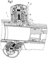
- Fig. 1 shows a vibration damper 1 with an inventive Damping valve 3, the functional and structural design of the vibration damper from DE 195 42 293 A1 as disclosed for this invention becomes.
- the damping valve 3 is arranged within a valve housing 5, which in turn consists of a valve block 7 and an end cap 9 which is screwed together are. Damping medium flows into the damping valve via an inflow opening 11 a.
- the damping valve comprises a first individual valve, which consists of an axial movable valve disc 13, which is on a valve seat 15 of the Valve block 7 supports.
- a spring 17 tensions the valve disc in the closing direction in front.
- the biasing length of the spring 17 is by means of an outside of the damper valve housing 5 accessible drive sleeve 19 adjustable, which extends through the end cap 9.
- the adjustment is made by a support surface 21 of the spring 17th is axially displaced.
- the support surface is made functional by a sliding sleeve 23 provided, with a possibly between the spring and the support surface Washer 25 can be arranged.
- a translation device effective which consists of a thread 27 between the drive sleeve and the sliding sleeve 23 and an axial guide 29 between the valve block 7 and the sliding sleeve 23.
- a rotary movement of the drive sleeve is transferred to the sliding sleeve, the starting from the thread 27 superimposed rotation and axial movement of the threads into a pure axial movement is implemented since the axial guide 29 between the valve block and the sliding sleeve prevents the sliding sleeve from rotating.
- the axial guide can for example be designed as a wedge profile. The moves Sliding sleeve relative to axially stationary drive sleeve.
- the drive sleeve will starting from the valve seat surface 15 via the valve disk 13 by means of the spring 17, which, as already described, acts on the sliding sleeve via the Thread 27 biased against an end face 31 of the end cap 9 and thus held axially stationary.
- the operating pressure in the vibration damper also acts in the same way.
- a locking device is used to secure the set preload length of the spring 17, which from a locking profile 33 in the end face 31 of the end cap 9, a Locking profile 35 in a shoulder 37 of the drive sleeve 19 and spherical locking bodies 39 exists.
- the locking profiles are conical depressions, which are formed in the circumferential direction in the end face and the shoulder and can be covered.
- the damping valve 3 also includes another a second single valve 43, this single valve with regard to smaller ones Operating pressures and thus damping forces in the vibration damper is designed.
- the second individual valve 43 includes a valve element, which by means of a control edge 45 on a support sleeve 47.
- the carrier sleeve has a central inflow opening 49 and a discharge opening 51 for the damping medium.
- the cross-section overlap between the drain opening and the control edge determines the pre-opening cross-section for the damping force range less Operating pressures.
- the pre-opening cross-section corresponds of the second valve 43 is the cross section of the drain opening 51.
- a check valve with a spherical body 50 ensures that the second individual valve can only be flowed through in one direction. Assuming that for every direction of movement of the vibration damper and thus the direction of flow of the damping medium, a damping valve 3 is provided, because of the check valve, the pre-opening cross-section is also set depending on the direction will.
- the carrier sleeve is concentric within the valve housing 9 arranged to the first single valve and is radial from a gradation of Drive sleeve 19 out.
- the carrier sleeve has openings in the area of the gradation 53, in which the drive sleeve engages in a form-fitting manner. During installation the two components are simply screwed together and, if necessary, with a Thread locking paste secured. Disassembly is still possible if necessary.
- the drive sleeve and the carrier sleeve are therefore practical as one component consider.
- a clamping sleeve 55 is installed within the carrier sleeve 47, with the help of which the bias of a spring acting on the valve element 45 57 of the second individual valve can adjust.
- an adjusting device 59 is used in addition to the clamping sleeve 55 also has a rotating element 61.
- the twisting element is accessible from the outside like the drive sleeve and also has Tool surfaces 41.
- the rotating element 61 can be rotated to the support sleeve 47.
- the twisting element On his inward facing At the end, the twisting element has a web 63 which is connected to a cutting edge Screwdriver is like. This web engages in a slot 65 of the clamping sleeve 55 a, which is connected to the carrier sleeve via a thread. At a Twisting movement of the twisting element becomes the clamping sleeve over the web also twisted.
- a thread 67 acts between the adapter sleeve and the Carrier sleeve, whereby the adapter sleeve performs an axial movement.
- the second individual valve can also be in its via a locking device 69 Lock the setting.
- the openings 53 in the carrier sleeve serve as latching openings and a transverse opening 71 in the rotating element as a corresponding counter profile, spherical locking body 73 according to the design of the first Single valve a positive connection between the carrier sleeve and the rotating element produce.
- the transverse opening 71 makes provision very easy of the space for receiving a detent spring 75.
- the two individual valves can be set completely independently of one another. If the drive sleeve 19 in the circumferential direction or between the locking stages axially moved, the carrier sleeve also performs this movement (s). The entire second single valve with its valve seat 45a and the valve body However, 45 is installed within the carrier sleeve 47 so that these movements exert no influence on the function of the second individual valve. Vice versa the second single valve can be adjusted to the first single valve. Even if one assumes that the spring forces that hold the catch are in both Valves are the same size, so the lever arm for the adjustment device for the second single valve is significantly smaller than the lever arm for the locking device between the drive sleeve and the end cap, so that the second single valve is adjustable independently of the first single valve.
- FIG. 3 shows a modification of the functional unit consisting of drive sleeve 61 and clamping sleeve 55 in a one-piece structural unit.
- the main functional difference is that diaphragms 77 of different diameters d i are incorporated in the clamping sleeve section, which overlap with the outflow opening 51 determine the pre-opening cross-section or the passage cross-section of the second valve and thereby a stepped setting can be made.
- the clamping sleeve section is no longer moved axially, since there is an axial fixation between the drive sleeve 19 and a step of the carrier sleeve 47 (see FIG. 2).
- the thread 67 from FIG. 2 can be omitted.
- Another advantage is that with one revolution of the entire element, a large number of pre-opening cross sections, in this embodiment 8 stages d 1 to d 7 and the closed pre-opening cross section between d 7 and d 1 , can be realized.
- care must be taken that the thread pitch of the thread 67 is not chosen too small, since otherwise, for example, the pre-opening step 6 will overlap with the pre-opening step 1 on the display on the end face of the twisting element, practically one Art clock dial effect occurs.
- FIG. 3 corresponds exactly the components 59, 55 and 61. You can the valve part of FIG. 3 as a Insert the cartridge into the installation space of Fig. 2.
Landscapes
- Engineering & Computer Science (AREA)
- General Engineering & Computer Science (AREA)
- Mechanical Engineering (AREA)
- Fluid-Damping Devices (AREA)
- Safety Valves (AREA)
- Lift Valve (AREA)
Abstract
Description
- Fig. 1
- Schwingungsdämpfer mit verstellbarem Dämpfventil
- Fig. 2
- Dämpfventil in einer Ausschnittdarstellung
Claims (10)
- Einstellbares Dämpfventil in einem Dämpfventilgehäuse für einen Schwingungsdämpfer, umfassend einen Ventilblock mit einer Zuströmöffnung im Bereich einer Ventilsitzfläche, auf der sich eine Ventilscheibe abstützt, die auf ihrer Rückseite von einer Feder vorgespannt ist, wobei die Vorspannung der Feder zur Veränderung der Dämpfkraft einstellbar ist, indem eine Abstützfläche der Feder verschiebbar ist,
dadurch gekennzeichnet,
daß die Abstützfläche (21) mit einer Rasteinrichtung (33; 35; 39) in Wirkverbindung steht, wobei die Rasteinrichtung stufenweise arretierbar ist, indem die Feder (17), die auf die Ventilscheibe (13) einwirkt, Rastkörper (39) der Rasteinrichtung in einem Rastprofil (35) kraftbeaufschlägt. - Dämpfventil nach Anspruch 1,
dadurch gekennzeichnet,
daß Rasteinrichtung eine verdrehbare Antriebshülse (19) aufweist, die mit einer Verschiebehülse (23) zusammenwirkt, wobei die Verschiebehülse die Abstützfläche (21) aufweist und mittels einer Übersetzungseinrichtung (27; 29) die Drehbewegung der Antriebshülse als eine Axialbewegung ausführt. - Dämpfventil nach Anspruch 2,
dadurch gekennzeichnet,
daß die Übersetzungseinrichtung aus einem Gewinde (27) zwischen der Antriebshülse und der Verschiebehülse (23) besteht, wobei die Bewegungsfähigkeit der Verschiebehülse durch eine Axialführung (29) in Umfangsrichtung blockiert ist. - Dämpfventil nach Anspruch 1,
dadurch gekennzeichnet,
daß als Rastkörper (39) Kugeln eingesetzt werden, die in dem Äquator der Kugeln angepaßte Vertiefungen des Rastprofils (33; 35) einrasten. - Dämpfventil nach Anspruch 1,
dadurch gekennzeichnet,
daß konzentrisch ein weiteres Dämpfventil (43; 45; 57) angeordnet ist, wobei das weitere Dämpfventil aus einer innenliegenden Trägerhülse (47) besteht, in der ein federbelastetes Ventilelement (45) angeordnet ist, wobei die Vorspannung der Feder (57) dieses Dämpfventils mittels einer von außerhalb des Ventilgehäuses zugänglichen Einstellvorrichtung (59) veränderbar ist, indem die Einspannlänge der Feder (57) veränderbar ist, wobei die Einstellvorrichtung ein Verdrehelement (61) aufweist, das relativ zur Trägerhülse verdrehbar ist, die wiederum bezogen auf das weitere Dämpfventil als ortsfest zu betrachten ist, wobei die mögliche Drehbewegung des Verdrehelementes mittels einer zweiten Rasterung (69; 53; 73) arretierbar ist. - Dämpfventil nach Anspruch 5,
dadurch gekennzeichnet,
daß die zweite Rasterung zwischen der Trägerhülse (47) und der Einstellvorrichtung (59) angeordnet ist. - Dämpfventil nach Anspruch 5,
dadurch gekennzeichnet,
daß das Verdrehelement (61) über einen Formschluß in Umfangsrichtung in Eingriff mit einer Spannhülse (55) steht, die axial aber relativ zum Verdrehelement beweglich ist, wobei zwischen der Spannhülse und der Trägerhülse eine Gewindeverbindung (67) vorliegt, so daß eine Bewegung des Verdrehelementes in eine Axialbewegung der Spannhülse umgesetzt wird. - Dämpfventil nach Anspruch 5,
dadurch gekennzeichnet,
daß das Verdrehelement (61) eine Queröffnung (71) aufweist, in der eine Rastfeder (75) im wesentlichen horizontal angeordnet ist, die auf mindestens einen Rastkörper (73) der zweiten Rasteinrichtung einwirkt. - Dämpfventil nach Anspruch 8,
dadurch gekennzeichnet,
daß in der Queröffnung (71) die Rastfeder (75) zwischen zwei gegenüberliegenden Rastkörpern (73) verspannt ist. - Dämpfventil nach Anspruch 5,
dadurch gekennzeichnet,
daß die Rastkörper (73) in Rastöffnungen (53) der Trägerhülse (47) eingreifen, von denen mindestens eine als eine Durchgangsöffnung ausgeführt ist und einen Formschluß mit der Antriebshülse (19) des einen Teilventils (13; 15; 17) eingeht.
Applications Claiming Priority (2)
| Application Number | Priority Date | Filing Date | Title |
|---|---|---|---|
| DE19724328A DE19724328C1 (de) | 1997-06-10 | 1997-06-10 | Dämpfventil mit einstellbarer Dämpfkraft |
| DE19724328 | 1997-06-10 |
Publications (3)
| Publication Number | Publication Date |
|---|---|
| EP0884500A2 true EP0884500A2 (de) | 1998-12-16 |
| EP0884500A3 EP0884500A3 (de) | 2000-03-01 |
| EP0884500B1 EP0884500B1 (de) | 2003-08-20 |
Family
ID=7831971
Family Applications (1)
| Application Number | Title | Priority Date | Filing Date |
|---|---|---|---|
| EP98107379A Expired - Lifetime EP0884500B1 (de) | 1997-06-10 | 1998-04-23 | Dämpfventil mit einstellbarer Dämpfkraft |
Country Status (4)
| Country | Link |
|---|---|
| US (1) | US6102171A (de) |
| EP (1) | EP0884500B1 (de) |
| DE (2) | DE19724328C1 (de) |
| ES (1) | ES2206781T3 (de) |
Cited By (1)
| Publication number | Priority date | Publication date | Assignee | Title |
|---|---|---|---|---|
| WO2000052353A1 (en) * | 1999-03-02 | 2000-09-08 | Atb Sales Limited | Damper |
Families Citing this family (15)
| Publication number | Priority date | Publication date | Assignee | Title |
|---|---|---|---|---|
| FR2776731B1 (fr) * | 1998-03-31 | 2000-05-12 | Donerre Amortisseur | Dispositif de reglage d'amortisseur a huile |
| DE19853854A1 (de) * | 1998-11-23 | 2000-05-25 | Anton Pfeifer | Bodenventil für 2-Rohrdämpfer |
| DE19953372A1 (de) * | 1999-02-10 | 2000-08-17 | Sachs Race Eng Gmbh | Schwingungsdämpfer mit verstellbarer Dämpfkraft |
| DE10315088A1 (de) * | 2003-04-02 | 2004-10-14 | Gustav Magenwirth Gmbh & Co. Kg | Dämpfungssystem |
| DE10326415A1 (de) * | 2003-06-12 | 2004-09-16 | Thyssenkrupp Bilstein Gmbh | Vorrichtung zum Verstellen von Stoßdämpfern |
| US6880684B1 (en) * | 2003-07-18 | 2005-04-19 | Walker Evans | Flow regulator for a gas shock absorber |
| DE102005036553A1 (de) * | 2005-05-30 | 2006-12-07 | Bosch Rexroth Aktiengesellschaft | Einstellvorrichtung und Druckreduzierventil |
| DE102013002425B3 (de) * | 2013-02-11 | 2014-04-24 | m-craft technologies ltd. | Stoßdämpfer mit einer sich automatisch anpassenden Dämpfungscharakteristik |
| DE102015218296B4 (de) | 2014-09-23 | 2024-04-18 | Zf Friedrichshafen Ag | Schwingungsdämpfer |
| EP3021001A1 (de) * | 2014-11-13 | 2016-05-18 | Öhlins Racing Ab | Durchflusseinstellvorrichtung |
| JP6417281B2 (ja) * | 2015-06-10 | 2018-11-07 | Kyb株式会社 | 緩衝器 |
| CN107060710A (zh) * | 2017-03-15 | 2017-08-18 | 上海嘉地仪器有限公司 | 桥式同心配聚器 |
| GB2585035B (en) * | 2019-06-25 | 2023-04-26 | Intersurgical Ag | An adjustable valve |
| US12330459B2 (en) * | 2021-02-01 | 2025-06-17 | Fox Factory, Inc. | Three-port adjuster |
| US11906015B2 (en) | 2022-01-03 | 2024-02-20 | DRiV Automotive Inc. | Damper with a slanted elliptical seal between an intermediate tube and an inner pressure tube |
Citations (1)
| Publication number | Priority date | Publication date | Assignee | Title |
|---|---|---|---|---|
| DE19542293A1 (de) | 1994-12-03 | 1996-06-20 | Fichtel & Sachs Ag | Schwingungsdämpfer mit einstellbarer Dämpfkraft |
Family Cites Families (7)
| Publication number | Priority date | Publication date | Assignee | Title |
|---|---|---|---|---|
| US3528531A (en) * | 1968-11-21 | 1970-09-15 | Gen Motors Corp | Adjustable orifice shock absorber |
| US4076225A (en) * | 1976-11-15 | 1978-02-28 | Enidine Incorporated | Adjustable energy absorbing device providing linear deceleration |
| JPS53117170A (en) * | 1977-03-22 | 1978-10-13 | Honda Motor Co Ltd | Regulator of damping force changing mechanism for rolling stock |
| GB2084289B (en) * | 1980-07-04 | 1985-06-19 | Tokico Ltd | Hydraulic damper with adjustable bypass |
| JPS58180846A (ja) * | 1982-04-16 | 1983-10-22 | Showa Mfg Co Ltd | 油圧緩衝器の減衰力発生装置 |
| JP3516102B2 (ja) * | 1995-03-27 | 2004-04-05 | カヤバ工業株式会社 | 減衰力調整部構造 |
| DE19547910C1 (de) * | 1995-12-21 | 1997-01-16 | Bilstein August Gmbh Co Kg | Vorrichtung zur Beeinflussung von Kennlinien eines Schwingungsdämpfers |
-
1997
- 1997-06-10 DE DE19724328A patent/DE19724328C1/de not_active Expired - Fee Related
-
1998
- 1998-04-23 DE DE59809323T patent/DE59809323D1/de not_active Expired - Fee Related
- 1998-04-23 ES ES98107379T patent/ES2206781T3/es not_active Expired - Lifetime
- 1998-04-23 EP EP98107379A patent/EP0884500B1/de not_active Expired - Lifetime
- 1998-06-10 US US09/090,020 patent/US6102171A/en not_active Expired - Fee Related
Patent Citations (1)
| Publication number | Priority date | Publication date | Assignee | Title |
|---|---|---|---|---|
| DE19542293A1 (de) | 1994-12-03 | 1996-06-20 | Fichtel & Sachs Ag | Schwingungsdämpfer mit einstellbarer Dämpfkraft |
Cited By (1)
| Publication number | Priority date | Publication date | Assignee | Title |
|---|---|---|---|---|
| WO2000052353A1 (en) * | 1999-03-02 | 2000-09-08 | Atb Sales Limited | Damper |
Also Published As
| Publication number | Publication date |
|---|---|
| EP0884500A3 (de) | 2000-03-01 |
| DE59809323D1 (de) | 2003-09-25 |
| US6102171A (en) | 2000-08-15 |
| EP0884500B1 (de) | 2003-08-20 |
| ES2206781T3 (es) | 2004-05-16 |
| DE19724328C1 (de) | 1998-10-29 |
Similar Documents
| Publication | Publication Date | Title |
|---|---|---|
| EP0884500B1 (de) | Dämpfventil mit einstellbarer Dämpfkraft | |
| DE60207518T2 (de) | Dämpfungseinrichtung | |
| EP0622142B1 (de) | Werkzeughalter, insbesondere Schnellwechselfutter | |
| EP1588006A1 (de) | Türfeststeller | |
| DE2942363A1 (de) | Drehschieber mit auswechselbarer patrone | |
| EP1588007A1 (de) | Türfeststeller | |
| WO2015132254A1 (de) | Kolben-zylinder-einheit und türscharnier mit einer kolben-zylinder-einheit | |
| EP3929458B1 (de) | Selbstsichernder vorspannring für federbeine | |
| EP2189558B1 (de) | Oberwalzen-Trag- und Belastungsarm für ein Streckwerk | |
| DE2057275A1 (de) | Progressivdaempfer,einstellbar ueber Veraenderung der Durchflusslaenge | |
| EP0517951B1 (de) | Befestigung für einen ein Laufelement aufweisenden Lagerkörper einer Längsführung | |
| DE10232029B4 (de) | Neigungsverstellbeschlag für Rückenlehnen von Kraftfahrzeugsitzen | |
| EP1446599A1 (de) | Vorrichtung zum verriegeln eines längsbeweglich geführten bauteiles | |
| CH709360A2 (de) | Selbstschliessendes Rollentürband. | |
| EP0783855B1 (de) | Verstellbare Fussanordnung für Möbel | |
| EP0663253B1 (de) | Spanneinrichtung an Werkzeugmaschinen mit einem umlaufenden Spannzylinder | |
| DE102023108690B4 (de) | Schwenkwiegenlagerung | |
| DE102004057946B4 (de) | Anschlagelement für eine Fahrzeug-Tür und Verfahren zur Einstellung einer Anschlagfläche eines Anschlagelementes für eine Fahrzeug-Tür | |
| DE102006059346B4 (de) | Lagersitzanordnung zur axialen und radialen Fixierung | |
| EP0858542B1 (de) | Federgelenk mit parametervorgabe | |
| DE4132709C2 (de) | Verstelldrosselventil | |
| EP2230338B1 (de) | Oberwalzen- Trag- und Belastungsarm für ein Streckwerk | |
| EP4263981A1 (de) | Betätigungshandhabe für rosettenlose fenster und türen | |
| WO2023208997A1 (de) | Scharnierband für eine gebäudetür oder ein gebäudefenster | |
| DE10046724A1 (de) | In ein Kraftfahrzeug eingebautes Ablagefach |
Legal Events
| Date | Code | Title | Description |
|---|---|---|---|
| PUAI | Public reference made under article 153(3) epc to a published international application that has entered the european phase |
Free format text: ORIGINAL CODE: 0009012 |
|
| AK | Designated contracting states |
Kind code of ref document: A2 Designated state(s): DE ES FR GB IT |
|
| AX | Request for extension of the european patent |
Free format text: AL;LT;LV;MK;RO;SI |
|
| PUAL | Search report despatched |
Free format text: ORIGINAL CODE: 0009013 |
|
| AK | Designated contracting states |
Kind code of ref document: A3 Designated state(s): AT BE CH CY DE DK ES FI FR GB GR IE IT LI LU MC NL PT SE |
|
| AX | Request for extension of the european patent |
Free format text: AL;LT;LV;MK;RO;SI |
|
| RIC1 | Information provided on ipc code assigned before grant |
Free format text: 7F 16F 9/44 A, 7F 16K 35/04 B |
|
| 17P | Request for examination filed |
Effective date: 20000404 |
|
| AKX | Designation fees paid |
Free format text: DE ES FR GB IT |
|
| RAP1 | Party data changed (applicant data changed or rights of an application transferred) |
Owner name: ZF SACHS AG |
|
| 17Q | First examination report despatched |
Effective date: 20020220 |
|
| GRAH | Despatch of communication of intention to grant a patent |
Free format text: ORIGINAL CODE: EPIDOS IGRA |
|
| GRAS | Grant fee paid |
Free format text: ORIGINAL CODE: EPIDOSNIGR3 |
|
| GRAA | (expected) grant |
Free format text: ORIGINAL CODE: 0009210 |
|
| AK | Designated contracting states |
Designated state(s): DE ES FR GB IT |
|
| REG | Reference to a national code |
Ref country code: GB Ref legal event code: FG4D Free format text: NOT ENGLISH |
|
| REF | Corresponds to: |
Ref document number: 59809323 Country of ref document: DE Date of ref document: 20030925 Kind code of ref document: P |
|
| GBT | Gb: translation of ep patent filed (gb section 77(6)(a)/1977) |
Effective date: 20031113 |
|
| ET | Fr: translation filed | ||
| REG | Reference to a national code |
Ref country code: ES Ref legal event code: FG2A Ref document number: 2206781 Country of ref document: ES Kind code of ref document: T3 |
|
| RIC2 | Information provided on ipc code assigned after grant |
Ipc: 7F 16K 35/04 A |
|
| PLBE | No opposition filed within time limit |
Free format text: ORIGINAL CODE: 0009261 |
|
| STAA | Information on the status of an ep patent application or granted ep patent |
Free format text: STATUS: NO OPPOSITION FILED WITHIN TIME LIMIT |
|
| 26N | No opposition filed |
Effective date: 20040524 |
|
| PGFP | Annual fee paid to national office [announced via postgrant information from national office to epo] |
Ref country code: FR Payment date: 20080312 Year of fee payment: 11 Ref country code: ES Payment date: 20080520 Year of fee payment: 11 Ref country code: DE Payment date: 20080502 Year of fee payment: 11 |
|
| PGFP | Annual fee paid to national office [announced via postgrant information from national office to epo] |
Ref country code: IT Payment date: 20080428 Year of fee payment: 11 |
|
| PGFP | Annual fee paid to national office [announced via postgrant information from national office to epo] |
Ref country code: GB Payment date: 20080423 Year of fee payment: 11 |
|
| GBPC | Gb: european patent ceased through non-payment of renewal fee |
Effective date: 20090423 |
|
| REG | Reference to a national code |
Ref country code: FR Ref legal event code: ST Effective date: 20091231 |
|
| PG25 | Lapsed in a contracting state [announced via postgrant information from national office to epo] |
Ref country code: DE Free format text: LAPSE BECAUSE OF NON-PAYMENT OF DUE FEES Effective date: 20091103 |
|
| PG25 | Lapsed in a contracting state [announced via postgrant information from national office to epo] |
Ref country code: GB Free format text: LAPSE BECAUSE OF NON-PAYMENT OF DUE FEES Effective date: 20090423 Ref country code: FR Free format text: LAPSE BECAUSE OF NON-PAYMENT OF DUE FEES Effective date: 20091222 |
|
| REG | Reference to a national code |
Ref country code: ES Ref legal event code: FD2A Effective date: 20090424 |
|
| PG25 | Lapsed in a contracting state [announced via postgrant information from national office to epo] |
Ref country code: ES Free format text: LAPSE BECAUSE OF NON-PAYMENT OF DUE FEES Effective date: 20090424 |
|
| PG25 | Lapsed in a contracting state [announced via postgrant information from national office to epo] |
Ref country code: IT Free format text: LAPSE BECAUSE OF NON-PAYMENT OF DUE FEES Effective date: 20090423 |