EP0882594B1 - Ink container with an inductive ink level detection machanism attached to a collapsible ink bag - Google Patents
Ink container with an inductive ink level detection machanism attached to a collapsible ink bag Download PDFInfo
- Publication number
- EP0882594B1 EP0882594B1 EP98103479A EP98103479A EP0882594B1 EP 0882594 B1 EP0882594 B1 EP 0882594B1 EP 98103479 A EP98103479 A EP 98103479A EP 98103479 A EP98103479 A EP 98103479A EP 0882594 B1 EP0882594 B1 EP 0882594B1
- Authority
- EP
- European Patent Office
- Prior art keywords
- ink
- coil
- inductive coil
- area
- attached
- Prior art date
- Legal status (The legal status is an assumption and is not a legal conclusion. Google has not performed a legal analysis and makes no representation as to the accuracy of the status listed.)
- Expired - Lifetime
Links
Images


Classifications
-
- B—PERFORMING OPERATIONS; TRANSPORTING
- B41—PRINTING; LINING MACHINES; TYPEWRITERS; STAMPS
- B41J—TYPEWRITERS; SELECTIVE PRINTING MECHANISMS, i.e. MECHANISMS PRINTING OTHERWISE THAN FROM A FORME; CORRECTION OF TYPOGRAPHICAL ERRORS
- B41J2/00—Typewriters or selective printing mechanisms characterised by the printing or marking process for which they are designed
- B41J2/005—Typewriters or selective printing mechanisms characterised by the printing or marking process for which they are designed characterised by bringing liquid or particles selectively into contact with a printing material
- B41J2/01—Ink jet
- B41J2/17—Ink jet characterised by ink handling
- B41J2/175—Ink supply systems ; Circuit parts therefor
- B41J2/17503—Ink cartridges
- B41J2/17556—Means for regulating the pressure in the cartridge
-
- B—PERFORMING OPERATIONS; TRANSPORTING
- B41—PRINTING; LINING MACHINES; TYPEWRITERS; STAMPS
- B41J—TYPEWRITERS; SELECTIVE PRINTING MECHANISMS, i.e. MECHANISMS PRINTING OTHERWISE THAN FROM A FORME; CORRECTION OF TYPOGRAPHICAL ERRORS
- B41J2/00—Typewriters or selective printing mechanisms characterised by the printing or marking process for which they are designed
- B41J2/005—Typewriters or selective printing mechanisms characterised by the printing or marking process for which they are designed characterised by bringing liquid or particles selectively into contact with a printing material
- B41J2/01—Ink jet
- B41J2/17—Ink jet characterised by ink handling
- B41J2/175—Ink supply systems ; Circuit parts therefor
- B41J2/17503—Ink cartridges
- B41J2/17506—Refilling of the cartridge
- B41J2/17509—Whilst mounted in the printer
-
- B—PERFORMING OPERATIONS; TRANSPORTING
- B41—PRINTING; LINING MACHINES; TYPEWRITERS; STAMPS
- B41J—TYPEWRITERS; SELECTIVE PRINTING MECHANISMS, i.e. MECHANISMS PRINTING OTHERWISE THAN FROM A FORME; CORRECTION OF TYPOGRAPHICAL ERRORS
- B41J2/00—Typewriters or selective printing mechanisms characterised by the printing or marking process for which they are designed
- B41J2/005—Typewriters or selective printing mechanisms characterised by the printing or marking process for which they are designed characterised by bringing liquid or particles selectively into contact with a printing material
- B41J2/01—Ink jet
- B41J2/17—Ink jet characterised by ink handling
- B41J2/175—Ink supply systems ; Circuit parts therefor
- B41J2/17503—Ink cartridges
- B41J2/17513—Inner structure
-
- B—PERFORMING OPERATIONS; TRANSPORTING
- B41—PRINTING; LINING MACHINES; TYPEWRITERS; STAMPS
- B41J—TYPEWRITERS; SELECTIVE PRINTING MECHANISMS, i.e. MECHANISMS PRINTING OTHERWISE THAN FROM A FORME; CORRECTION OF TYPOGRAPHICAL ERRORS
- B41J2/00—Typewriters or selective printing mechanisms characterised by the printing or marking process for which they are designed
- B41J2/005—Typewriters or selective printing mechanisms characterised by the printing or marking process for which they are designed characterised by bringing liquid or particles selectively into contact with a printing material
- B41J2/01—Ink jet
- B41J2/17—Ink jet characterised by ink handling
- B41J2/175—Ink supply systems ; Circuit parts therefor
- B41J2/17503—Ink cartridges
- B41J2/1752—Mounting within the printer
-
- B—PERFORMING OPERATIONS; TRANSPORTING
- B41—PRINTING; LINING MACHINES; TYPEWRITERS; STAMPS
- B41J—TYPEWRITERS; SELECTIVE PRINTING MECHANISMS, i.e. MECHANISMS PRINTING OTHERWISE THAN FROM A FORME; CORRECTION OF TYPOGRAPHICAL ERRORS
- B41J2/00—Typewriters or selective printing mechanisms characterised by the printing or marking process for which they are designed
- B41J2/005—Typewriters or selective printing mechanisms characterised by the printing or marking process for which they are designed characterised by bringing liquid or particles selectively into contact with a printing material
- B41J2/01—Ink jet
- B41J2/17—Ink jet characterised by ink handling
- B41J2/175—Ink supply systems ; Circuit parts therefor
- B41J2/17503—Ink cartridges
- B41J2/17553—Outer structure
-
- B—PERFORMING OPERATIONS; TRANSPORTING
- B41—PRINTING; LINING MACHINES; TYPEWRITERS; STAMPS
- B41J—TYPEWRITERS; SELECTIVE PRINTING MECHANISMS, i.e. MECHANISMS PRINTING OTHERWISE THAN FROM A FORME; CORRECTION OF TYPOGRAPHICAL ERRORS
- B41J2/00—Typewriters or selective printing mechanisms characterised by the printing or marking process for which they are designed
- B41J2/005—Typewriters or selective printing mechanisms characterised by the printing or marking process for which they are designed characterised by bringing liquid or particles selectively into contact with a printing material
- B41J2/01—Ink jet
- B41J2/17—Ink jet characterised by ink handling
- B41J2/175—Ink supply systems ; Circuit parts therefor
- B41J2/17566—Ink level or ink residue control
-
- G—PHYSICS
- G01—MEASURING; TESTING
- G01F—MEASURING VOLUME, VOLUME FLOW, MASS FLOW OR LIQUID LEVEL; METERING BY VOLUME
- G01F23/00—Indicating or measuring liquid level or level of fluent solid material, e.g. indicating in terms of volume or indicating by means of an alarm
- G01F23/22—Indicating or measuring liquid level or level of fluent solid material, e.g. indicating in terms of volume or indicating by means of an alarm by measuring physical variables, other than linear dimensions, pressure or weight, dependent on the level to be measured, e.g. by difference of heat transfer of steam or water
- G01F23/26—Indicating or measuring liquid level or level of fluent solid material, e.g. indicating in terms of volume or indicating by means of an alarm by measuring physical variables, other than linear dimensions, pressure or weight, dependent on the level to be measured, e.g. by difference of heat transfer of steam or water by measuring variations of capacity or inductance of capacitors or inductors arising from the presence of liquid or fluent solid material in the electric or electromagnetic fields
-
- B—PERFORMING OPERATIONS; TRANSPORTING
- B41—PRINTING; LINING MACHINES; TYPEWRITERS; STAMPS
- B41J—TYPEWRITERS; SELECTIVE PRINTING MECHANISMS, i.e. MECHANISMS PRINTING OTHERWISE THAN FROM A FORME; CORRECTION OF TYPOGRAPHICAL ERRORS
- B41J2/00—Typewriters or selective printing mechanisms characterised by the printing or marking process for which they are designed
- B41J2/005—Typewriters or selective printing mechanisms characterised by the printing or marking process for which they are designed characterised by bringing liquid or particles selectively into contact with a printing material
- B41J2/01—Ink jet
- B41J2/17—Ink jet characterised by ink handling
- B41J2/175—Ink supply systems ; Circuit parts therefor
- B41J2/17503—Ink cartridges
- B41J2/17513—Inner structure
- B41J2002/17516—Inner structure comprising a collapsible ink holder, e.g. a flexible bag
Definitions
- the disclosed invention relates to ink jet printing systems that employ replaceable consumable parts including ink cartridges, and more particularly to mechanisms for estimating the amount of ink remaining in an ink cartridge.
- ink jet printing is relatively well developed.
- Commercial products such as computer printers, graphics plotters, and facsimile machines have been implemented with ink jet technology for producing printed media.
- an ink jet image is formed pursuant to precise placement on a print medium of ink drops emitted by an ink drop generating device known as an ink jet printhead.
- an ink jet printhead is supported on a movable carriage that traverses over the surface of the print medium and is controlled to eject drops of ink at appropriate times pursuant to command of a microcomputer or other controller, wherein the timing of the application of the ink drops is intended to correspond to a pattern of pixels of the image being printed.
- Some known printers make use of an ink container that is separably replaceable from the printhead. When the ink container is exhausted it is removed and replaced with a new ink container.
- replaceable ink containers that are separate from the printhead allow users to replace the ink container without replacing the printhead. The printhead is then replaced at or near the end of printhead life, and not when the ink container is replaced.
- ink jet printing systems that employ ink containers that are separate from the printheads.
- a known approach to estimating remaining ink volume involves immersing electrodes in an ink volume and measuring a resistance path through the ink. Considerations with this approach include the complexity of incorporating electrodes in an ink container, and the variation of electrical properties with ink formulation.
- US-A-4 415 886 discloses a collapsible ink reservoir that is provided with electrodes on opposing sides of an ink bag. A capacitor is formed by the electrodes and the ink disposed there between. The amount of ink remaining in the bag is determined by measuring the electrostatic capacity of said capacitor which decreases when the ink volume decreases.
- the invention is generally employed in an ink level detection system that includes a collapsible ink container having first a side and a second side that are opposing; a first inductive coil attached to the first side, the first inductive coil having a first coil area and first and second terminals; and a second inductive coil attached to the second side, the second inductive coil having a second coil area and first and second terminals.
- the second coil area is greater than the first coil area.
- the first and second sides of the ink reservoir include relatively stiff regions adjacent to the first and second coils.
- the number of turns of the second coil is greater than the number of turns of the first coil.
- a pressure vessel is provided for pressurizing the outside of the ink reservoir.
- FIG. 1 is a schematic block diagram of a printer/plotter system in which an ink level sensing circuit in accordance with the invention can be employed.
- FIG. 2 is a schematic block diagram depicting major components of one of the print cartridges of the printer/plotter system of FIG. 1.
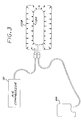
- FIG. 3 is a schematic block diagram illustrating in a simplified manner the connection between an off-carriage ink container, an air pressure source, and an on-carriage print cartridge of the printer/plotter system of FIG. 1.
- FIG. 4 is a schematic block diagram depicting major components of one of the ink containers of the printer/plotter system of FIG. 1.
- FIG. 5 a simplified isometric view of an implementation of the printer/plotter system of FIG. 1.
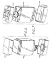
- FIG. 6 is a schematic isometric exploded view illustrating the major components of an implementation of one of the ink containers of the printer/plotter system of FIG. 1 which employs an ink level sensing circuit in accordance with the invention.
- FIG. 7 is a further schematic isometric exploded view illustrating the major components of an implementation of one of the ink containers of the printer/plotter system of FIG. 1 which employs an ink level sensing circuit in accordance with the invention.
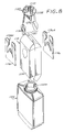
- FIG. 8 is an exploded isometric view showing the pressure vessel, collapsible ink reservoir, ink level sensing circuitry, ink reservoir stiffening elements, and chassis member of the ink container of FIGS. 6 and 7.
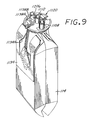
- FIG. 9 is a schematic isometric view illustrating the collapsible ink reservoir, ink level sensing circuitry, ink reservoir stiffening elements, and chassis member of the ink container of FIGS. 6 and 7.
- FIG. 10 is a cross-sectional view of the pressure vessel, collapsible ink reservoir, ink level sensing circuitry, ink reservoir stiffening elements, and chassis member of the ink container of FIGS. 6 and 7.
- FIG. 11 is an elevational view of the collapsible ink reservoir, ink level sensing circuitry, ink reservoir stiffening elements, and chassis member of the ink container of FIGS. 6 and 7, with the collapsible ink reservoir in a flattened evacuated state.
- FIG. 12 an edge view of the collapsible ink reservoir, ink level sensing circuitry, ink reservoir stiffening elements, and chassis member of the ink container of FIGS. 6 and 7, with the collapsible ink reservoir in a flattened evacuated state.
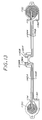
- FIG. 13 is a schematic plan view of an implementation of the ink level sensing circuit of the invention as employed in the ink container of FIGS. 6 and 7.
- FIG. 1 set forth therein is a schematic block diagram of a printer/plotter 50 in which the invention can be employed.
- a scanning print carriage 52 holds a plurality of print cartridges 60-66 which are fluidically coupled to an ink supply station 100 that supplies pressurized ink to the print cartridges 60-66.
- each of the cartridges 60-66 comprises an ink jet printhead and an integral printhead memory, as schematically depicted in FIG. 2 for the representative example of the print cartridge 60 which includes an ink jet printhead 60A and an integral printhead memory 60B.
- Each print cartridge has a fluidic regulator valve that opens and closes to maintain a slight negative gauge pressure in the cartridge that is optimal for printhead performance.
- the ink provided to each of the cartridges 60-66 is pressurized to reduce the effects of dynamic pressure drops.
- the ink supply station 100 contains receptacles or bays for accepting ink containers 110-116 which are respectively associated with and fluidically connected to respective print cartridges 60-66.
- Each of the ink containers 110-114 includes a collapsible ink reservoir, such as collapsible ink reservoir 110A that is surrounded by an air pressure chamber 110B.
- An air pressure source or pump 70 is in communication with the air pressure chamber for pressurizing the collapsible ink reservoir.
- one pressure pump supplies pressurized air for all ink containers in the system.
- Pressurized ink is delivered to the print cartridges by an ink flow path that includes for example respective flexible plastic tubes connected between the ink containers 110-116 and respectively associated print cartridges 60-66.
- FIG. 3 is a simplified diagrammatic view illustrating the pressure source 70, the print cartridge 66, and the collapsible ink reservoir 110a and pressure chamber 110B.
- the pressure chamber 110B (which is defined by a pressure vessel, as more particularly described herein) is allowed to de-pressurize. Also, the ink containers 110-116 are not pressurized during shipment.
- each of the ink containers 110-116 comprises an ink reservoir, an ink level sensing circuit, and an integral ink cartridge memory, as schematically depicted in FIG. 4 for the representative example of the ink container 110 which more particularly includes the ink reservoir 110A, an ink level sensing circuit 110C, and an integral ink cartridge memory 110D.
- the scanning print carriage 52, the print cartridges 60-66, and the ink containers 110-114 are electrically interconnected to a printer microprocessor controller 80 that includes printer electronics and firmware for the control of various printer functions, including analog-to-digital converter circuitry for converting the outputs of the ink level sensing circuits of the ink containers 110-116.
- the controller 80 thus controls the scan carriage drive system and the printheads on the print carriage to selectively energize the printheads, to cause ink droplets to be ejected in a controlled fashion on the print medium 40.
- the printer controller 80 further continually estimates remaining ink volume in each of the ink containers 110-114 pursuant to an ink level sensing circuit in accordance with the invention that is employed in each of the ink containers.
- a host processor 82 which includes a CPU 82A and a software printer driver 82B, is connected to the printer controller 82.
- the host processor 82 comprises a personal computer that is external to the printer 50.
- a monitor 84 is connected to the host processor 82 and is used to display various messages that are indicative of the state of the ink jet printer.
- the printer can be configured for stand-alone or networked operation wherein messages are displayed on a front panel of the printer.
- FIG. 5 shows in isometric view an exemplary form of a large format printer/plotter in which the invention can be employed, wherein four off-carriage ink containers 110, 112, 114, 116 are show in place in an ink supply station.
- the printer/plotter of FIG. 5 further includes a housing 54, a front control panel 56 which provides user control switches, and a media output slot 58. While this exemplary printer/plotter is fed from a media roll, it should be appreciated that alternative sheet feed mechanisms can also be used.
- FIGS. 6-13 schematically illustrated therein is a specific implementation of an ink container 200 which includes an ink level sensing circuit in accordance with the invention, and which can be implemented as each of the ink containers 110-116 which are structurally substantially identical.
- the ink container 200 generally includes a pressure vessel 1102, a chassis member 1120 attached to a neck region 1102A at a leading end of the pressure vessel 1102, a leading end cap 1104 attached to the leading end of the pressure vessel, and a trailing end cap 1106 attached to the trailing end of the pressure vessel 1102.
- the ink container 200 further includes a collapsible ink bag or reservoir 114 disposed within the pressure vessel 1102, and an ink level sensing (ILS) circuit 1170 attached to the collapsible ink reservoir 114.
- the collapsible ink reservoir 114 is sealingly attached to a keel portion 1292 of the chassis 1120 which seals the interior of the pressure vessel 1102 from outside atmosphere while providing for an air inlet 1108 to the interior of the pressure vessel 1102, an ink outlet port 1110 for ink contained in the ink reservoir 114 and routing for conductive traces between the ink level sensing circuit 1170 and externally accessible contact pads disposed on the chassis member.
- the chassis 1120 is secured to the opening of the neck region 1102A of the pressure vessel 1102, for example by an annular crimp ring 1280 that engages a top flange of the pressure vessel and an abutting flange of the chassis member.
- a pressure sealing O-ring 1152 suitably captured in a circumferential groove on the chassis 1120 engages the inside surface of the neck region 1102A of the pressure vessel 1102.
- the collapsible ink reservoir 114 more particularly comprises a pleated bag having opposing walls or sides 1114, 1116, and the ink level sensing circuit 1170 more particularly includes first and second substantially flat spiral inductive coils 1130, 1132 disposed on the opposing sides 1114, 1116.
- an elongated sheet of bag material is folded such that opposed lateral edges of the sheet overlap or are brought together, forming an elongated cylinder.
- the lateral edges are sealed together, and pleats are in the resulting structure generally in alignment with the seal of the lateral edges.
- the bottom or non-feed end of the bag is formed by heat sealing the pleated structure along a seam transverse to the seal of the lateral edges.
- the top or feed end of the ink reservoir is formed similarly while leaving an opening for the bag to be sealingly attached to the keel portion 1292 of the chassis 1120.
- the ink reservoir bag is sealingly attached to keel portion 1292 by heat staking.
- the ink reservoir 114 has a longitudinal axis that extends from feed end to non-feed end, and is parallel to the axis of the ink outlet port 1110.
- Stiffening elements 1134, 1136 are disposed on the opposing sides 1114, 1116 over the flat spiral inductive coils 1130, 1132 to enable a more predictable, consistent, and repeatable collapse of the ink reservoir 114 as the ink contained therein is depleted, to maintain the coils parallel to each other as the ink reservoir walls collapse toward each other while the remaining ink volume is in the range over which the ink level sensing circuit is active, and to reduce buckling of the ink reservoir in the region between the coils and the portion of the ink reservoir that is attached to the keel portion 1292.
- Maintaining the coils parallel to each other over a collapse range of interest with a more predictable, repeatable, and consistent collapse allows for more accurate sensing of ink remaining in the reservoir by adjacent the stiffening elements 1134, 1136.
- Pressurization within the pressure vessel also provides for more predictable and consistent collapse of the ink reservoir, with or without the stiffening elements 1134, 1136.
- each of the stiffener 1134, 1136 extends laterally across the wall to which it is attached, and includes a cut-out 1134A, 1136A that provides clearance for folds, bumps or wrinkles in the walls 1114, 1116 caused by the keel portion 1292 and by the attachment of the ink reservoir to the keel portion 1292.
- Each stiffener further extends longitudinally from the feed end of the ink reservoir to a location slightly beyond the side of the coil that is away from the feed end of the ink reservoir.
- the stiffening elements reduce buckling of the walls 1114, 1116 between the coils and the feed end of the ink reservoir and allow buckling at the non-feed end of the ink reservoir.
- the stiffening elements 1134, 1136 are preferably flat resiliently deformable stiff sheets that return to a planar configuration in the absence of the biasing forces applied to bend the stiffening elements for insertion into the pressure vessel.
- the stiffening elements are stiff and yet sufficiently resilient so as to be not permanently deformed by the curling required for insertion into the pressure vessel.
- the stiffening elements comprise relatively thin (e.g., .0005 inches) polyethylene terephthalate (PET) sheets.
- the stiffening elements effectively cooperate with the walls of the ink reservoir to form wall regions of increased stiffness whose collapse with ink depletion is consistent and repeatable, and it should be appreciated that regions of the opposite walls 1114, 1116 of the ink reservoir can be formed as regions of increased stiffness in which case the stiffening elements 1134, 1136 can be omitted.
- Each of the spiral coils 1130, 1132 can comprise a continuously curved winding having a perimeter that is generally defined by a conical section such as a circle or ellipse, for example, or each spiral coil can comprise a segmented winding comprised of serially connected segments having a perimeter that is generally defined by a polygon as a rectangle.
- the spiral coils 1130, 1132 are preferably positioned such that the line formed by their geometrical centers is orthogonal to the planes of the coils when the planes of the coils are parallel and when the ink reservoir is flat and without ink. In other words, the spiral coils 1130, 1132 are positioned such that their geometrical centers are substantially mirror images of each other on the walls 1114, 1116.
- the container 200 is preferably rotationally positioned about its longitudinal axis, which extends between the open end thereof and the opposite closed end, such that the planes of the coils are vertical.
- the areas of the stiffening elements 1134, 1136 are preferably greater than the areas of the respectively adjacent coils 1130, 1132. Also, the areas of the coils 1130, 1132 are respectively contained within the areas of the respectively adjacent stiffening elements 1134, 1136 (or rigid regions).
- the ink level sensing circuit 1170 can be used without pressurization.
- the ink level sensing circuit 1170 is implemented, for example, as a flexible circuit wherein the flat coils 1130, 1132 and associated conductive elements by which the flat coils can be electrically accessed are disposed in laminar fashion between first and second flat unitary flexible substrates.
- the ink level sensing circuit further includes conductive leads 1142A, 1142B which extend between the flat coil 1130 and externally accessible contact pads 1138A, 1138B; and conductive leads 1144A, 1144B which extend between the flat coil 1132 and externally accessible contact pads 1140A, 1140B.
- the foregoing contact pads are exposed by respective openings in the appropriate flexible substrate of the flexible circuit, and are externally accessible in the sense that they can be conductively engaged by contact elements external to the ink container 200.
- the externally accessible contact pads of the ink level sensing circuit are suitably disposed on the outside of the chassis 1120, and the conductive leads extend generally longitudinally within the pressure vessel 1102 from the chassis 1120 to the coils 1130, 1132. Portions of the conductive leads and associated portions of the flexible substrates of the ink level sensing circuit 1170 pass on the outside surface of the chassis between the O-ring 1152 and such outside surface.
- a suitably insulated jumper 1174 is connected between the conductive lead 1142A and the center of the flat coil 1130, while a suitable insulated jumper 1176 is connected between the conductive lead 1144A and the center of the flat coil 1132.
- the ink level sensing circuit further includes ink leakage detectors comprised of conductive ink leakage detection pads 1180, 1182 respectively located adjacent the coils 1130, 1132 and respectively connected to conductive leads 1142B, 1144B.
- the ink leakage pads 1180, 1182 are exposed by openings in the outward facing flexible substrate of the ink sensing flexible circuit and are not covered by the stiffening elements 1134, 1136 so as to be contactable with any ink that accumulates in the pressure vessel 1102 as a result of ink leakage.
- Ink leakage indicative of a broken ink reservoir, is detected for example by applying a voltage between the contact pad 1138B and a reference potential, and sensing the voltage between the contact pad 1140B and the reference potential.
- the contact pad 1140B would be at a non-zero voltage; otherwise, the contact pad 1140B would be at zero volts.
- the ink leakage contact pads 1180, 1182 are preferably rotationally positioned relative to the coils 1130, 1132 so as to be elevationally low when the ink container is in its intended installed position.
- the coil portions and the contact portions of the flexible circuit comprising the ink level sensing circuit 1170 are attached to the walls 1114, 1116 and the chassis 1120 with pressure sensitive adhesive.
- a memory chip package 1206 is also supported on the chassis 1120, for example between pairs of externally accessible ink level sensing circuit contact pads 1138A, 1138B and 1140A, 1140B.
- the memory chip package includes memory access contacts which are connected to the print controller 82 when the ink container 200 is installed in the printing system 50, as are the externally accessible ink level sensing circuit contact pads 1138A, 1138B, 1140A, 1140B.
- the coils 1130, 1132 function as a non-contactive inductive transducer that indirectly senses the amount of ink in the ink reservoir by sensing the separation between the opposing walls 1114, 1116 which collapse toward each other as the ink supply is depleted.
- An AC excitation signal is passed through one coil (considered the input coil), inducing a voltage in the other coil (considered the output coil) whose magnitude increases as the separation decreases.
- the change in voltage in the output coil results from the change in the mutual inductance of the coils with change in the separation between the coils.
- the output voltage provided by the output coil is readily related to a corresponding ink volume, e.g., by values stored in the ink container memory.
- the coils 1130, 1132 are positioned in areas of the ink reservoir that are subject to predictable, consistent and repeatable collapse. Further, the coils 1130, 1132 are positioned such that the ink level sensing circuit 1170 is active over a desired range of ink volume.
- the spiral coils 1130, 1132 are positioned closer to the ink outlet 1110, for example between the feed end of the reservoir which is attached to the chassis 1120 and the middle between the feed end of the ink reservoir and the opposite end.
- the ink container 200 can be installed with the longitudinal axis of the container being tilted relative to horizontal by an angle in the range of about 5 to 30 degrees such that the chassis is elevationally lower that the opposite of the ink container, and with the ink container rotationally positioned about the longitudinal axis so that the planes of the ink level sensing coils are vertical.
- the coils can be positioned slightly off the lateral middle (wherein the lateral direction is orthogonal to the longitudinal direction) for installations wherein longitudinal axis of the ink reservoir is more horizontal than vertical.
- the ink level sensing coils can be displaced toward what would be the elevationally higher edge of the walls 1114, 1116 by about 4 degrees, for example, whereby the coils are tilted up in the installed position relative to the longitudinal axis of the ink reservoir.
- the coil area of the coil 1132 is larger than the coil area of the coil 1130, as the input coil, in at least one direction and not smaller than the coil area of the coil 1130 in any direction, such that if the output coil area and the input coil area were superimposed, the output coil area would completely overlap the input coil area and extend beyond the input coil area in at least one direction, wherein the coil area of a coil is the area occupied by the turns of the coil and the gap between adjacent turns.
- a coil area can be also considered as the area enclosed by the periphery of a coil.
- the input coil area can be completely contained within the output coil area, if such areas were placed on top of each other.
- the output coil area and input coil can be similarly shaped (i.e., of the same shape), and the output coil area would have a bigger shape.
- the coil area of the output coil has a radius that is greater than the radius of the coil area of the input coil.
- the output coil area would have a width that is greater than the width of the input coil, and a length that is greater than or equal to the length of the input coil.
- the input coil area is completely containable within the output coil area which greater than the input coil area in at least one dimension or direction.
- the coil 1132 as the output coil, includes a greater number of turns than the coil 1130, as the input coil, without limitation as to the relative areas of the coils.
- a larger output coil area that completely contains the input coil area and extends beyond the output coil area in at least one direction increases the tolerance in the alignment between the coils 1130, 1132 in at least one direction, which allows for easier manufacture.
- a larger number of turns in the output coil increases the level of the voltage of the coil output, which increases the accuracy of ink volume sensing.
Landscapes
- Physics & Mathematics (AREA)
- Thermal Sciences (AREA)
- Fluid Mechanics (AREA)
- General Physics & Mathematics (AREA)
- Engineering & Computer Science (AREA)
- Electromagnetism (AREA)
- Power Engineering (AREA)
- Ink Jet (AREA)
- Measurement Of Levels Of Liquids Or Fluent Solid Materials (AREA)
Applications Claiming Priority (2)
| Application Number | Priority Date | Filing Date | Title |
|---|---|---|---|
| US08/869,240 US6164743A (en) | 1996-04-17 | 1997-06-04 | Ink container with an inductive ink level sense |
| US869240 | 1997-06-04 |
Publications (2)
| Publication Number | Publication Date |
|---|---|
| EP0882594A1 EP0882594A1 (en) | 1998-12-09 |
| EP0882594B1 true EP0882594B1 (en) | 2000-10-18 |
Family
ID=25353176
Family Applications (1)
| Application Number | Title | Priority Date | Filing Date |
|---|---|---|---|
| EP98103479A Expired - Lifetime EP0882594B1 (en) | 1997-06-04 | 1998-02-27 | Ink container with an inductive ink level detection machanism attached to a collapsible ink bag |
Country Status (7)
| Country | Link |
|---|---|
| US (1) | US6164743A (https=) |
| EP (1) | EP0882594B1 (https=) |
| JP (1) | JP4286340B2 (https=) |
| KR (1) | KR100525872B1 (https=) |
| CN (1) | CN1153049C (https=) |
| DE (1) | DE69800353T2 (https=) |
| ES (1) | ES2151302T3 (https=) |
Families Citing this family (56)
| Publication number | Priority date | Publication date | Assignee | Title |
|---|---|---|---|---|
| US6390590B1 (en) * | 1999-01-21 | 2002-05-21 | Oki Data Americas, Inc. | Apparatus for recording information about an ink cartridge |
| EP1120258B1 (en) | 2000-01-21 | 2006-05-17 | Seiko Epson Corporation | Ink cartridge, and ink-jet recording apparatus using the same |
| KR100617280B1 (ko) | 2000-01-21 | 2006-08-30 | 세이코 엡슨 가부시키가이샤 | 잉크 카트리지 및 잉크젯식 기록 장치 |
| US6685296B2 (en) * | 2000-06-16 | 2004-02-03 | Canon Kabushiki Kaisha | Ink tank and ink jet recording apparatus provided with the same |
| DE10056602C1 (de) * | 2000-11-15 | 2002-04-04 | Roehm Gmbh | Beschriftungsvorrichtung und Extrusionsanlage mit einer solchen Beschriftungsvorrichtung |
| CN1303405C (zh) * | 2001-02-22 | 2007-03-07 | 明基电通股份有限公司 | 墨水存量检测装置 |
| USD468346S1 (en) | 2001-03-09 | 2003-01-07 | Lectra Sa | Ink tank case |
| US6454381B1 (en) * | 2001-04-27 | 2002-09-24 | Hewlett-Packard Company | Method and apparatus for providing ink container extraction characteristics to a printing system |
| USD485859S1 (en) | 2001-07-05 | 2004-01-27 | Olympus Corporation | Cap for an ink bottle |
| USD472918S1 (en) | 2001-07-05 | 2003-04-08 | Olympus Optical Co., Ltd. | Ink bottle with a cap |
| US6505926B1 (en) | 2001-08-16 | 2003-01-14 | Eastman Kodak Company | Ink cartridge with memory chip and method of assembling |
| USD462383S1 (en) | 2001-08-16 | 2002-09-03 | Eastman Kodak Company | Ink cartridge with ink color discrimination structure |
| USD462986S1 (en) | 2001-08-16 | 2002-09-17 | Eastman Kodak Company | Handle for an ink cartridge |
| USD462089S1 (en) | 2001-08-16 | 2002-08-27 | Eastman Kodak Company | Ink cartridge |
| USD485572S1 (en) | 2002-01-11 | 2004-01-20 | Olympus Corporation | Ink bottle |
| USD472920S1 (en) | 2002-01-11 | 2003-04-08 | Olympus Optical Co., Ltd. | Ink bottle |
| US20040012660A1 (en) * | 2002-07-18 | 2004-01-22 | Eastman Kodak Company | Ink cartridge having connectable-disconnectable housing and ink supply bag |
| US6702435B2 (en) | 2002-07-18 | 2004-03-09 | Eastman Kodak Company | Ink cartridge having ink identifier oriented to provide ink identification |
| US6715864B2 (en) | 2002-07-18 | 2004-04-06 | Eastman Kodak Company | Disposable ink supply bag having connector-fitting |
| US6712459B2 (en) | 2002-07-18 | 2004-03-30 | Eastman Kodak Company | Ink cartridge having shielded pocket for memory chip |
| US6705713B2 (en) | 2002-07-18 | 2004-03-16 | Eastman Kodak Company | Disposable ink assemblage |
| US6755501B2 (en) | 2002-08-08 | 2004-06-29 | Eastman Kodak Company | Alternative ink/cleaner cartridge |
| US6709093B2 (en) | 2002-08-08 | 2004-03-23 | Eastman Kodak Company | Ink cartridge in which ink supply bag held fast to housing |
| US6830323B2 (en) | 2002-08-13 | 2004-12-14 | Eastman Kodak Company | Restricting flash spread when welding housing halves of cartridge together |
| US6705714B1 (en) | 2002-08-21 | 2004-03-16 | Eastman Kodak Company | Ink cartridge having ink supply bag filled to less than capacity and folded in cartridge housing |
| US6837576B2 (en) | 2002-08-21 | 2005-01-04 | Eastman Kodak Company | Method of filling ink supply bag for ink cartridge |
| US6886929B2 (en) * | 2002-10-25 | 2005-05-03 | Hewlett-Packard Development Company, L.P. | Techniques for improving pressure sensor shock robustness in fluid containment devices |
| US7465040B2 (en) * | 2002-10-25 | 2008-12-16 | Hewlett-Packard Development Company, L.P. | Labyrinth seal structure with redundant fluid flow paths |
| ATE393009T1 (de) | 2002-11-12 | 2008-05-15 | Objet Geometries Ltd | Verfahren und system zum drucken eines dreidimensionalen gegenstandes |
| US6962078B2 (en) | 2002-12-24 | 2005-11-08 | Lexmark International, Inc. | Liquid level detection gauge and associated methods |
| JP4289963B2 (ja) * | 2003-09-29 | 2009-07-01 | キヤノン株式会社 | インクタンクおよび記録装置 |
| USD523075S1 (en) * | 2004-02-06 | 2006-06-13 | Brother Industries, Ltd. | Ink cartridge |
| US7454955B2 (en) | 2004-10-29 | 2008-11-25 | Hewlett-Packard Development Company, L.P. | Leak detection structure |
| ES2324358T3 (es) * | 2004-10-27 | 2009-08-05 | Hewlett-Packard Development Company, L.P. | Estructura de deteccion de fugas. |
| US7766469B2 (en) * | 2005-09-29 | 2010-08-03 | Brother Kogyo Kabushiki Kaisha | Ink cartridges |
| UA108344C2 (uk) * | 2005-12-26 | 2015-04-27 | Контейнер з матеріалом для друкування і плата, яка встановлюється на контейнері з матеріалом для друкування | |
| JP4144637B2 (ja) | 2005-12-26 | 2008-09-03 | セイコーエプソン株式会社 | 印刷材収容体、基板、印刷装置および印刷材収容体を準備する方法 |
| JP4356717B2 (ja) * | 2006-08-11 | 2009-11-04 | セイコーエプソン株式会社 | 液体収容容器 |
| WO2011093527A1 (en) * | 2010-01-29 | 2011-08-04 | Brother Kogyo Kabushiki Kaisha | Ink cartridge, recording device, and method for controlling recording device |
| JP5381757B2 (ja) | 2010-01-29 | 2014-01-08 | ブラザー工業株式会社 | インクカートリッジ |
| JP5506452B2 (ja) * | 2010-02-25 | 2014-05-28 | エスアイアイ・プリンテック株式会社 | 圧力緩衝器、液体噴射ヘッド及び液体噴射装置 |
| JP5565029B2 (ja) * | 2010-03-29 | 2014-08-06 | セイコーエプソン株式会社 | 液体容器および液体消費装置 |
| JP5731853B2 (ja) * | 2011-02-24 | 2015-06-10 | エスアイアイ・プリンテック株式会社 | 圧力緩衝器、液体噴射ヘッド及び液体噴射装置 |
| WO2012153432A1 (ja) | 2011-05-09 | 2012-11-15 | ブラザー工業株式会社 | インクカートリッジ及び記録装置 |
| US8801161B2 (en) | 2011-07-27 | 2014-08-12 | Brother Kogyo Kabushiki Kaisha | Liquid cartridge, image recording device, and substrate |
| RU2558010C2 (ru) * | 2013-10-15 | 2015-07-27 | Владимир Дмитриевич Таранин | Индуктивный уровнемер жидкометаллического теплоносителя |
| US9132648B2 (en) | 2014-02-19 | 2015-09-15 | Ricoh Company, Ltd. | Fluid cartridge label stiffener |
| US10300702B2 (en) | 2015-07-22 | 2019-05-28 | Hewlett-Packard Development Company, L.P. | Printing fluid container |
| EP3337663B1 (en) | 2015-11-10 | 2020-05-06 | Hewlett-Packard Development Company, L.P. | Printhead-integrated ink level sensor with central clearing resistor |
| JP6840741B2 (ja) * | 2015-12-11 | 2021-03-10 | ヒューレット−パッカード デベロップメント カンパニー エル.ピー.Hewlett‐Packard Development Company, L.P. | 折り畳み式容器及びセンサー |
| CN109070617B (zh) * | 2016-04-29 | 2021-02-09 | 惠普发展公司,有限责任合伙企业 | 用于检测液位的打印装置和方法 |
| WO2017204808A1 (en) * | 2016-05-26 | 2017-11-30 | Hewlett-Packard Develoment Company, L.P. | Buffer reservoirs |
| CN109564126B (zh) * | 2016-07-21 | 2021-10-19 | 惠普发展公司,有限责任合伙企业 | 液体液位感测 |
| US9937725B1 (en) * | 2017-02-17 | 2018-04-10 | Funai Electric Co., Ltd. | Fluidic dispensing device |
| US11535037B1 (en) | 2021-12-28 | 2022-12-27 | Seiko Epson Corporation | Device, board, liquid accommodation container, and printing system |
| CN117848449B (zh) * | 2022-09-30 | 2026-03-20 | 珠海奔图电子有限公司 | 一种检测装置、图像形成设备及检测方法 |
Family Cites Families (13)
| Publication number | Priority date | Publication date | Assignee | Title |
|---|---|---|---|---|
| AU543299B2 (en) * | 1979-06-11 | 1985-04-18 | Geotronics Metaltech A.B. | Determining melt level in ladle |
| JPS5734990A (en) * | 1980-08-12 | 1982-02-25 | Canon Inc | Apparatus for detecting ink residual amount |
| DE3043810A1 (de) * | 1980-11-20 | 1982-06-24 | Siemens AG, 1000 Berlin und 8000 München | Vorrichtung zur ueberwachung des tintenvorrats in tintenschreibeinrichtungen |
| US4446562A (en) * | 1981-10-13 | 1984-05-01 | Electric Power Rsearch Institute, Inc. | Method and apparatus for measuring crucible level of molten metal |
| DE3422504A1 (de) * | 1984-06-16 | 1986-01-02 | Olympia Werke Ag, 2940 Wilhelmshaven | Endanzeigevorrichtung des tintenvorrats in einem tintenbehaelter mit einem flexiblen tintensack |
| US4568954A (en) * | 1984-12-06 | 1986-02-04 | Tektronix, Inc. | Ink cartridge manufacturing method and apparatus |
| DE3524250A1 (de) * | 1985-07-06 | 1987-01-08 | Philips Patentverwaltung | Anordnung zur kontrolle des fuellstandes eines tintenbehaelters |
| JPS63207652A (ja) * | 1987-02-25 | 1988-08-29 | Seiko Epson Corp | インク残量検出装置 |
| JPS6418087A (en) * | 1987-07-14 | 1989-01-20 | Toshiba Corp | Electromagnetic induction detector |
| US5051921A (en) * | 1989-11-30 | 1991-09-24 | David Sarnoff Research Center, Inc. | Method and apparatus for detecting liquid composition and actual liquid level |
| US5583545A (en) * | 1994-10-31 | 1996-12-10 | Hewlett-Packard Company | Ink level detection in a pressure regulated pen |
| US5635962A (en) * | 1995-07-24 | 1997-06-03 | Hewlett-Packard Company | Capacitive ink level detection sensor |
| DE19642899A1 (de) * | 1996-04-17 | 1997-10-23 | Hewlett Packard Co | Induktive Tintenpegelerfassungsvorrichtung für Tintenvorräte |
-
1997
- 1997-06-04 US US08/869,240 patent/US6164743A/en not_active Expired - Lifetime
-
1998
- 1998-02-27 EP EP98103479A patent/EP0882594B1/en not_active Expired - Lifetime
- 1998-02-27 ES ES98103479T patent/ES2151302T3/es not_active Expired - Lifetime
- 1998-02-27 DE DE69800353T patent/DE69800353T2/de not_active Expired - Lifetime
- 1998-06-03 JP JP15478298A patent/JP4286340B2/ja not_active Expired - Lifetime
- 1998-06-03 KR KR10-1998-0020569A patent/KR100525872B1/ko not_active Expired - Lifetime
- 1998-06-04 CN CNB981096107A patent/CN1153049C/zh not_active Expired - Lifetime
Also Published As
| Publication number | Publication date |
|---|---|
| CN1203358A (zh) | 1998-12-30 |
| JP4286340B2 (ja) | 2009-06-24 |
| JPH10337879A (ja) | 1998-12-22 |
| DE69800353T2 (de) | 2001-05-23 |
| ES2151302T3 (es) | 2000-12-16 |
| KR19990006631A (ko) | 1999-01-25 |
| DE69800353D1 (de) | 2000-11-23 |
| CN1153049C (zh) | 2004-06-09 |
| US6164743A (en) | 2000-12-26 |
| EP0882594A1 (en) | 1998-12-09 |
| KR100525872B1 (ko) | 2005-12-21 |
Similar Documents
| Publication | Publication Date | Title |
|---|---|---|
| EP0882594B1 (en) | Ink container with an inductive ink level detection machanism attached to a collapsible ink bag | |
| EP0882595B1 (en) | Ink level estimation using drop count and ink level sense | |
| US6435638B1 (en) | Ink bag fitment with an integrated pressure sensor for low ink detection | |
| EP1203666B1 (en) | Pressure-based Ink level sense enhancement using a pressure controlling element in an Ink bag | |
| EP1310372B1 (en) | Ink container providing pressurized ink with ink level sensor | |
| US6010210A (en) | Ink container having a multiple function chassis | |
| US6017118A (en) | High performance ink container with efficient construction | |
| EP1914079B1 (en) | Pressure sensor with shock protection in fluid container |
Legal Events
| Date | Code | Title | Description |
|---|---|---|---|
| PUAI | Public reference made under article 153(3) epc to a published international application that has entered the european phase |
Free format text: ORIGINAL CODE: 0009012 |
|
| AK | Designated contracting states |
Kind code of ref document: A1 Designated state(s): DE ES FR GB IT |
|
| AX | Request for extension of the european patent |
Free format text: AL;LT;LV;MK;RO;SI |
|
| 17P | Request for examination filed |
Effective date: 19981228 |
|
| AKX | Designation fees paid |
Free format text: DE ES FR GB IT |
|
| GRAG | Despatch of communication of intention to grant |
Free format text: ORIGINAL CODE: EPIDOS AGRA |
|
| 17Q | First examination report despatched |
Effective date: 20000105 |
|
| GRAG | Despatch of communication of intention to grant |
Free format text: ORIGINAL CODE: EPIDOS AGRA |
|
| GRAH | Despatch of communication of intention to grant a patent |
Free format text: ORIGINAL CODE: EPIDOS IGRA |
|
| GRAH | Despatch of communication of intention to grant a patent |
Free format text: ORIGINAL CODE: EPIDOS IGRA |
|
| GRAA | (expected) grant |
Free format text: ORIGINAL CODE: 0009210 |
|
| AK | Designated contracting states |
Kind code of ref document: B1 Designated state(s): DE ES FR GB IT |
|
| REF | Corresponds to: |
Ref document number: 69800353 Country of ref document: DE Date of ref document: 20001123 |
|
| ET | Fr: translation filed | ||
| REG | Reference to a national code |
Ref country code: ES Ref legal event code: FG2A Ref document number: 2151302 Country of ref document: ES Kind code of ref document: T3 |
|
| ITF | It: translation for a ep patent filed | ||
| RAP2 | Party data changed (patent owner data changed or rights of a patent transferred) |
Owner name: HEWLETT-PACKARD COMPANY, A DELAWARE CORPORATION |
|
| PLBE | No opposition filed within time limit |
Free format text: ORIGINAL CODE: 0009261 |
|
| STAA | Information on the status of an ep patent application or granted ep patent |
Free format text: STATUS: NO OPPOSITION FILED WITHIN TIME LIMIT |
|
| 26N | No opposition filed | ||
| REG | Reference to a national code |
Ref country code: GB Ref legal event code: IF02 |
|
| REG | Reference to a national code |
Ref country code: GB Ref legal event code: 732E |
|
| REG | Reference to a national code |
Ref country code: FR Ref legal event code: TP |
|
| REG | Reference to a national code |
Ref country code: GB Ref legal event code: 732E Free format text: REGISTERED BETWEEN 20120329 AND 20120404 |
|
| REG | Reference to a national code |
Ref country code: ES Ref legal event code: PC2A Owner name: HEWLETT-PACKARD DEVELOPMENT COMPANY, L.P. Effective date: 20120911 |
|
| REG | Reference to a national code |
Ref country code: FR Ref legal event code: PLFP Year of fee payment: 19 |
|
| REG | Reference to a national code |
Ref country code: FR Ref legal event code: PLFP Year of fee payment: 20 |
|
| PGFP | Annual fee paid to national office [announced via postgrant information from national office to epo] |
Ref country code: FR Payment date: 20170124 Year of fee payment: 20 Ref country code: DE Payment date: 20170119 Year of fee payment: 20 |
|
| PGFP | Annual fee paid to national office [announced via postgrant information from national office to epo] |
Ref country code: GB Payment date: 20170124 Year of fee payment: 20 |
|
| PGFP | Annual fee paid to national office [announced via postgrant information from national office to epo] |
Ref country code: IT Payment date: 20170120 Year of fee payment: 20 Ref country code: ES Payment date: 20170123 Year of fee payment: 20 |
|
| REG | Reference to a national code |
Ref country code: DE Ref legal event code: R071 Ref document number: 69800353 Country of ref document: DE |
|
| REG | Reference to a national code |
Ref country code: GB Ref legal event code: PE20 Expiry date: 20180226 |
|
| PG25 | Lapsed in a contracting state [announced via postgrant information from national office to epo] |
Ref country code: GB Free format text: LAPSE BECAUSE OF EXPIRATION OF PROTECTION Effective date: 20180226 |
|
| REG | Reference to a national code |
Ref country code: ES Ref legal event code: FD2A Effective date: 20200723 |
|
| PG25 | Lapsed in a contracting state [announced via postgrant information from national office to epo] |
Ref country code: ES Free format text: LAPSE BECAUSE OF EXPIRATION OF PROTECTION Effective date: 20180228 |