EP0881369A2 - Moteur à combustion interne - Google Patents
Moteur à combustion interne Download PDFInfo
- Publication number
- EP0881369A2 EP0881369A2 EP98109547A EP98109547A EP0881369A2 EP 0881369 A2 EP0881369 A2 EP 0881369A2 EP 98109547 A EP98109547 A EP 98109547A EP 98109547 A EP98109547 A EP 98109547A EP 0881369 A2 EP0881369 A2 EP 0881369A2
- Authority
- EP
- European Patent Office
- Prior art keywords
- cylinder
- intake
- intake port
- section
- internal combustion
- Prior art date
- Legal status (The legal status is an assumption and is not a legal conclusion. Google has not performed a legal analysis and makes no representation as to the accuracy of the status listed.)
- Granted
Links
Images
Classifications
-
- F—MECHANICAL ENGINEERING; LIGHTING; HEATING; WEAPONS; BLASTING
- F02—COMBUSTION ENGINES; HOT-GAS OR COMBUSTION-PRODUCT ENGINE PLANTS
- F02B—INTERNAL-COMBUSTION PISTON ENGINES; COMBUSTION ENGINES IN GENERAL
- F02B23/00—Other engines characterised by special shape or construction of combustion chambers to improve operation
- F02B23/08—Other engines characterised by special shape or construction of combustion chambers to improve operation with positive ignition
- F02B23/10—Other engines characterised by special shape or construction of combustion chambers to improve operation with positive ignition with separate admission of air and fuel into cylinder
- F02B23/104—Other engines characterised by special shape or construction of combustion chambers to improve operation with positive ignition with separate admission of air and fuel into cylinder the injector being placed on a side position of the cylinder
-
- F—MECHANICAL ENGINEERING; LIGHTING; HEATING; WEAPONS; BLASTING
- F02—COMBUSTION ENGINES; HOT-GAS OR COMBUSTION-PRODUCT ENGINE PLANTS
- F02F—CYLINDERS, PISTONS OR CASINGS, FOR COMBUSTION ENGINES; ARRANGEMENTS OF SEALINGS IN COMBUSTION ENGINES
- F02F1/00—Cylinders; Cylinder heads
- F02F1/24—Cylinder heads
- F02F1/42—Shape or arrangement of intake or exhaust channels in cylinder heads
-
- F—MECHANICAL ENGINEERING; LIGHTING; HEATING; WEAPONS; BLASTING
- F02—COMBUSTION ENGINES; HOT-GAS OR COMBUSTION-PRODUCT ENGINE PLANTS
- F02B—INTERNAL-COMBUSTION PISTON ENGINES; COMBUSTION ENGINES IN GENERAL
- F02B23/00—Other engines characterised by special shape or construction of combustion chambers to improve operation
- F02B23/08—Other engines characterised by special shape or construction of combustion chambers to improve operation with positive ignition
- F02B23/10—Other engines characterised by special shape or construction of combustion chambers to improve operation with positive ignition with separate admission of air and fuel into cylinder
-
- F—MECHANICAL ENGINEERING; LIGHTING; HEATING; WEAPONS; BLASTING
- F02—COMBUSTION ENGINES; HOT-GAS OR COMBUSTION-PRODUCT ENGINE PLANTS
- F02B—INTERNAL-COMBUSTION PISTON ENGINES; COMBUSTION ENGINES IN GENERAL
- F02B31/00—Modifying induction systems for imparting a rotation to the charge in the cylinder
-
- F—MECHANICAL ENGINEERING; LIGHTING; HEATING; WEAPONS; BLASTING
- F02—COMBUSTION ENGINES; HOT-GAS OR COMBUSTION-PRODUCT ENGINE PLANTS
- F02F—CYLINDERS, PISTONS OR CASINGS, FOR COMBUSTION ENGINES; ARRANGEMENTS OF SEALINGS IN COMBUSTION ENGINES
- F02F1/00—Cylinders; Cylinder heads
- F02F1/24—Cylinder heads
- F02F1/42—Shape or arrangement of intake or exhaust channels in cylinder heads
- F02F1/4214—Shape or arrangement of intake or exhaust channels in cylinder heads specially adapted for four or more valves per cylinder
-
- F—MECHANICAL ENGINEERING; LIGHTING; HEATING; WEAPONS; BLASTING
- F02—COMBUSTION ENGINES; HOT-GAS OR COMBUSTION-PRODUCT ENGINE PLANTS
- F02F—CYLINDERS, PISTONS OR CASINGS, FOR COMBUSTION ENGINES; ARRANGEMENTS OF SEALINGS IN COMBUSTION ENGINES
- F02F3/00—Pistons
- F02F3/26—Pistons having combustion chamber in piston head
-
- F—MECHANICAL ENGINEERING; LIGHTING; HEATING; WEAPONS; BLASTING
- F02—COMBUSTION ENGINES; HOT-GAS OR COMBUSTION-PRODUCT ENGINE PLANTS
- F02B—INTERNAL-COMBUSTION PISTON ENGINES; COMBUSTION ENGINES IN GENERAL
- F02B23/00—Other engines characterised by special shape or construction of combustion chambers to improve operation
- F02B23/08—Other engines characterised by special shape or construction of combustion chambers to improve operation with positive ignition
- F02B23/10—Other engines characterised by special shape or construction of combustion chambers to improve operation with positive ignition with separate admission of air and fuel into cylinder
- F02B2023/106—Tumble flow, i.e. the axis of rotation of the main charge flow motion is horizontal
-
- F—MECHANICAL ENGINEERING; LIGHTING; HEATING; WEAPONS; BLASTING
- F02—COMBUSTION ENGINES; HOT-GAS OR COMBUSTION-PRODUCT ENGINE PLANTS
- F02B—INTERNAL-COMBUSTION PISTON ENGINES; COMBUSTION ENGINES IN GENERAL
- F02B23/00—Other engines characterised by special shape or construction of combustion chambers to improve operation
- F02B23/08—Other engines characterised by special shape or construction of combustion chambers to improve operation with positive ignition
- F02B23/10—Other engines characterised by special shape or construction of combustion chambers to improve operation with positive ignition with separate admission of air and fuel into cylinder
- F02B2023/108—Swirl flow, i.e. the axis of rotation of the main charge flow motion is vertical
-
- F—MECHANICAL ENGINEERING; LIGHTING; HEATING; WEAPONS; BLASTING
- F02—COMBUSTION ENGINES; HOT-GAS OR COMBUSTION-PRODUCT ENGINE PLANTS
- F02B—INTERNAL-COMBUSTION PISTON ENGINES; COMBUSTION ENGINES IN GENERAL
- F02B75/00—Other engines
- F02B75/12—Other methods of operation
- F02B2075/125—Direct injection in the combustion chamber for spark ignition engines, i.e. not in pre-combustion chamber
-
- F—MECHANICAL ENGINEERING; LIGHTING; HEATING; WEAPONS; BLASTING
- F02—COMBUSTION ENGINES; HOT-GAS OR COMBUSTION-PRODUCT ENGINE PLANTS
- F02B—INTERNAL-COMBUSTION PISTON ENGINES; COMBUSTION ENGINES IN GENERAL
- F02B2275/00—Other engines, components or details, not provided for in other groups of this subclass
- F02B2275/48—Tumble motion in gas movement in cylinder
-
- F—MECHANICAL ENGINEERING; LIGHTING; HEATING; WEAPONS; BLASTING
- F02—COMBUSTION ENGINES; HOT-GAS OR COMBUSTION-PRODUCT ENGINE PLANTS
- F02F—CYLINDERS, PISTONS OR CASINGS, FOR COMBUSTION ENGINES; ARRANGEMENTS OF SEALINGS IN COMBUSTION ENGINES
- F02F1/00—Cylinders; Cylinder heads
- F02F1/24—Cylinder heads
- F02F2001/244—Arrangement of valve stems in cylinder heads
- F02F2001/245—Arrangement of valve stems in cylinder heads the valve stems being orientated at an angle with the cylinder axis
-
- Y—GENERAL TAGGING OF NEW TECHNOLOGICAL DEVELOPMENTS; GENERAL TAGGING OF CROSS-SECTIONAL TECHNOLOGIES SPANNING OVER SEVERAL SECTIONS OF THE IPC; TECHNICAL SUBJECTS COVERED BY FORMER USPC CROSS-REFERENCE ART COLLECTIONS [XRACs] AND DIGESTS
- Y02—TECHNOLOGIES OR APPLICATIONS FOR MITIGATION OR ADAPTATION AGAINST CLIMATE CHANGE
- Y02T—CLIMATE CHANGE MITIGATION TECHNOLOGIES RELATED TO TRANSPORTATION
- Y02T10/00—Road transport of goods or passengers
- Y02T10/10—Internal combustion engine [ICE] based vehicles
- Y02T10/12—Improving ICE efficiencies
Definitions
- This invention relates to improvements in an internal combustion engine, and more particularly to the improvements in shape of an intake port of the engine.
- an intake port is formed in a cylinder head and shaped such that its downstream section (at a combustion chamber side) is gently inclined relative to the bottom flat surface of the cylinder head while its upstream section (at an intake pipe side) is further gently inclined to be generally horizontal relative to the bottom flat surface, as disclosed, for example, in Japanese Utility Model Provisional Publication No. 7-25236.
- the intake port in case that the inclination angle of the intake port relative to the cylinder head bottom flat surface is relatively large, the intake port is called “high port”. In case that the inclination angle of the intake port is relatively small, the intake port is called “low port”. If the intake port extends generally parallel with the cylinder head bottom flat surface, the intake port is called “horizontal port”. In this connection, conventional general intake ports are arranged such that the downstream section takes the “low port” construction while the upstream section takes the "horizontal port” construction.
- the downstream section of the "low port” construction is advantageous from the viewpoint of increasing an amount of intake air directed to an exhaust valve in a cylinder thereby enhancing tumble flow of intake air in the cylinder.
- it is required to ensure a sufficient length of intake air passage within a limited space in an automotive vehicle for the purpose of obtaining a sufficient engine torque output.
- the upstream section takes the "horizontal port” or “low port” construction, this requirement is met by sharply bending the intake pipe (intake manifold) connected to the upstream section of the intake port so that the radius of curvature of the intake pipe becomes small, or otherwise by forming a plurality of bent portions.
- the fuel injector valve is disposed close to the intake port and located closer to the periphery of the combustion chamber than the downstream end of the intake port.
- the cylinder direct injection spark ignition engine is provided with two intake ports for each cylinder, it is preferable to dispose the fuel injector valve between the two intake ports.
- Another object of the present invention is to provide an improved internal combustion engine which can obtain a sufficient length of an intake pipe (intake manifold) while enhancing tumble flow of intake air in a cylinder.
- a further object of the present invention is to provide an improved internal combustion engine which can facilitate disposition of a fuel injector valve and machining a fuel injector valve accommodating hole, in case that the engine is of a cylinder direct injection spark-ignition type.
- An aspect of the present invention resides in an internal combustion engine comprising a cylinder head having an intake port.
- the intake port has first and second sections which are contiguous with each other.
- the first section is located downstream of the second section relative to flow of intake air.
- the first and second sections have respectively first and second axes.
- the first and second axes incline relative to a bottom flat surface of the cylinder head respectively to form first and second angles, in which the first angle is smaller than the second angle.
- the engine comprises a cylinder block having a plurality of cylinders.
- a cylinder head is fixedly mounted on a block deck of the cylinder block.
- the cylinder head has an intake port for each cylinder.
- the intake port has first and second sections which are contiguous with each other.
- the first section is located downstream of the second section relative to flow of intake air.
- the first and second sections have respectively first and second axes.
- the first and second axes incline relative to a bottom flat surface of the cylinder head respectively to form first and second angles, in which the first angle is smaller than the second angle.
- a fuel injector valve is provided to directly inject fuel into a combustion chamber formed corresponding to each cylinder.
- the fuel injector valve is located close to the intake port and disposed closer to a periphery of the combustion chamber than a downstream end of the intake port.
- a spark plug is provided in such a manner that its tip end section is projected into the combustion chamber.
- the first or downstream-side section of the intake port takes the "low port” construction, and therefore tumble flow of intake air in the cylinder is enhanced thereby increasing combustion speed of air-fuel mixture in the combustion chamber thus improving combustion performance of the engine.
- the second or upstream-side section of the intake port takes the "high port” construction, and therefore a sufficient length of the intake port can be ensured while ensuring a sufficient length of an intake pipe (intake manifold) merely by gently bending the intake pipe with a relatively large radius of curvature.
- a fuel injector valve and an accommodation hole for the fuel injector valve can be effectively prevented from interfering the intake port by virtue of the fact that the upstream-side section of the intake port takes the "high port" construction.
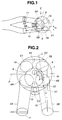
- FIG. 1 to 7 an embodiment of a cylinder direction injection spark-ignition (gasoline-fueled) internal combustion engine according to the present invention is illustrated by the reference character E.
- the engine E of this embodiment is for an automotive vehicle and has a plurality of engine cylinders C formed in a cylinder block 3 though only one cylinder C is shown.
- a piston 4 is movably disposed in each cylinder C to define a combustion chamber 1 between it and a cylinder head 2 which is secured at its bottom flat surface B to the block deck (cylinder upper-deck) or top flat surface T of the cylinder block 3.
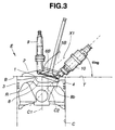
- the cylinder head 2 is formed with two (first and second) intake ports 5A, 5B and two exhaust ports E1, E2 (shown in Fig. 2) for each cylinder C or for each combustion chamber 1.
- the two intake ports 5A, 5B are located at an opposite side of a vertical cylinder head plane P with respect to the two exhaust ports E1, E2, in which the vertical cylinder head plane P contains the center axes (not shown) of the cylinders C.
- the intake ports 5A, 5B have respectively downstream ends (opened to the combustion chamber 1) at which two intake valves 6A, 6B are respectively movably disposed.
- the exhaust ports E1, E2 have respectively upstream ends (opened to the combustion chamber 1) at which two exhaust valves 7A, 7B are respectively movably disposed.
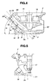
- the piston 4 is formed at its piston crown with a circular cavity or depression 8 forming part of the combustion chamber 1. More specifically, the cavity 8 is formed at the top surface of the piston crown and shallow or flat so that that its bottom surface 8b is generally flat.
- the center axis C2 of the cavity 8 is generally parallel with and offset from the center axis C1 of the piston 4 toward the intake valves 6A, 6B, i.e., located closer to the intake valves 6A, 6B than to the exhaust valves 7A, 7B.
- the periphery 8a of the cavity 8 is generally circular as viewed from the above as seen in Fig. 2.
- a part of the periphery 8a of the cavity 8 is raised over the other part of the periphery 8a to form a ridgeline R as shown in Fig. 3, the part being located at an opposite side of an imaginary vertical plane (not shown) containing the center axis C2, with respect to a side in which a fuel injector valve 10 is located.
- a spark plug 9 is installed to the cylinder head 2 so that its tip end section (having electrodes) projects into the combustion chamber 1 and located above a part of the peripheral annular portion of the circular cavity 8.
- the spark plug 9 is positioned generally along the center axis C1 of the cylinder C. Specifically, the axis of the spark plug 9 is slightly offset from the center axis C1 of the cylinder C toward the exhaust valves 7A, 7B.
- the fuel injector valve 10 is disposed between the first and second intake ports 5A, 5B as viewed from the above as shown in Fig. 2 and positioned to inject fuel (gasoline) directly into the combustion chamber 1.
- the fuel injector valve 10 is installed to be directed obliquely downward and extends in a direction from the intake valves 6A, 6B to the exhaust valves 7A, 7B.
- the fuel injector valve 10 is positioned such that its axis (indicated by a dotted line) forms a predetermined angle ⁇ inj relative to the top flat surface T of the cylinder block 3 (or relative to the bottom flat surface of the cylinder head 2) and is directed to the bottom surface 8b of the cavity 8.
- the predetermined angle ⁇ inj is within a range of from 35 degrees to 45 degrees, preferably about 45 degrees. Accordingly, the fuel injector valve 10 injects fuel in an obliquely downward direction or toward the cavity 8.
- the fuel injector valve 10 is arranged to inject fuel at a fuel injection timing which is set, in this embodiment, in compression stroke under the engine operating condition in which stratified charge combustion is to be carried out.
- a swirl control valve 11 is movably disposed to block the first intake port 5A and arranged to be controllably opened or closed in accordance with an engine operating condition.
- the swirl control valve 11 is controlled to be generally fully closed, in a predetermined engine operating condition in which stratified charge combustion is to be carried out.
- the swirl control valve 11 may be partly closed to control air flow in the first intake port 5A in another predetermined engine operating condition.
- the second intake port 5B is formed extending generally tangentially to the periphery 8a of the cavity 8.
- a vertical port axis plane L containing the axis X1 (or at least a major part of the axis X1) of the second intake port 5B is inclined relative to a vertical cross flow plane V1 in a manner to gradually approach the center axis C1 of the piston 4 in a direction toward the combustion chamber 1, in which a predetermined angle (port inwardly directing angle) ⁇ 1 is formed between the vertical port axis plane L and the vertical cross flow plane V1.
- the predetermined angle ⁇ 1 is within a range of not smaller than 5 degrees and smaller than 15 degrees, preferably about 8 degrees.
- the vertical port axis plane L is generally parallel with a vertical plane V2 containing a tangent line of the periphery 8a of the circular cavity 8 on an imaginary horizontal plane or the bock deck H of the cylinder block 3.
- the vertical port axis plane L is located inside the vertical plane V2 and extends passing through a space outside the spark plug 9 and inside relative to the periphery 8a of the circular cavity 8. It will be understood that the vertical port axis plane L, the vertical cross flow plane V1, and the vertical plane V2 are vertical to the block deck or top flat surface H of the cylinder block 3.
- the vertical cross flow plane V1 passes through the intake valve 6B and the exhaust valve 7B and is perpendicular to the cylinder axis plane P which contains the axes of the cylinders C. It will be understood that the cylinder axis plane P is vertical to the block deck H.
- the predetermined angle ⁇ 1 is an angle of inward inclination of the intake port 5B (more specifically, the intake port axis X1) relative to a cross-flow horizontal direction V1.
- the predetermined angle ⁇ 1 may also be defined as a horizontally measured angle formed between the intake port axis X1 and a line V1, where the line V1 is in a vertical plane that both extends through an intake valve 6B and an exhaust valve 7B and is perpendicular to the vertical cylinder axis plane P containing the center axes of the adjacent cylinders.
- the swirl control valve 11 is closed under an engine operating condition (for example, a low load engine operating condition) in which stratified charge combustion is to be carried out. Consequently, intake air is introduced through the second intake port 5B into the combustion chamber 1, in which intake air generates gas flow W in the form of swirl as shown in Fig. 2.
- the gas flow W is inside the cavity 8 formed at the piston crown and moves along the periphery 8a of the cavity 8.
- the first intake port 5A blockable with the swirl control valve 11 is formed and shaped generally symmetrical to the second intake port 5B with respect to a vertical central plane V3 which contains the center axis C2 of the cavity 8 and the center axis C1 of the piston 4 and parallel with the vertical cross flow plane V1, so that the axes of the first and second intake ports 5A, 5B gradually approach to each other in the direction toward the combustion chamber 1 as clearly shown in Fig. 2.
- the tip end (having the electrodes) of the spark plug 9 is located inside relative to the vertical port axis plane L containing the axis X1 of the second intake port 5B.
- the spark plug 9 is positioned such that the vertical central plane V3 passes through the tip end section of the spark plug 9.
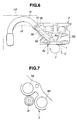
- the cylinder head 2 is formed at the bottom flat surface B with a depression 2a forming part of the combustion chamber 1.
- the depression or combustion chamber 2a is located at the generally central part in a widthwise direction (or in a right and left direction in Fig. 4) of the cylinder head 1.
- Reference numerals 15, 16 denote respectively holes for accommodating the intake and exhaust valves 6B, 7B.
- a spark plug accommodating hole 17 is formed in the cylinder head 1 to be located in such that its axis is parallel with and close to the center axis C1 of the cylinder C.
- the spark plug 9 is to be accommodated in the hole 17.
- a fuel injector valve accommodating hole 18 is formed in the cylinder head 2 and located near the intake ports 5A, 5B. More specifically, the fuel injector valve accommodating hole 18 is located between the two intake ports 5A, 5B as viewed from an upper side or on a horizontal plane containing the bottom flat surface B of the cylinder head 1. The bottom flat surface B is in tight contact with the top flat surface T of the cylinder block 3. The tip end section of the fuel injector valve accommodating hole 18 is located close to the periphery 8a of the combustion chamber 1 or the cylinder C.
- the fuel injector valve 10 is accommodated in this hole 18 in such a manner as to directly inject fuel obliquely downward into the combustion chamber 1.
- the fuel injector valve 10 is adapted to inject fuel at an injection timing in intake stroke during homogeneous charge combustion, and at an injection timing in compression stroke during stratified charge combustion.
- each intake port 5A, 5B is formed to be directed obliquely downward relative to the combustion chamber 1.
- the intake port 5A, 5B includes a downstream-side section 5a and an upstream-side section 5b which are contiguous with each other.
- the downstream-side section 5a is located between the combustion chamber 1 and the upstream-side section 5b, while the upstream-side section 5b is located between the downstream-side section 5a and an intake pipe 19 (in Fig. 6).
- the intake port 5A, 5B has its axis X1 which includes a downstream-side axis portion Xa, and an upstream-side axis portion Xb.
- the downstream-side axis portion Xa serves as the axis of the downstream-side section 5a of the intake port 3
- the upstream-side axis portion Xb serves as the axis of the upstream-side section 5b of the intake port 5A, 5B.
- the downstream-side and upstream-side axis portions Xa, Xb are connected with each other at a point A.
- the downstream-side axis portion Xa inclines relative to the bottom flat surface B of the cylinder head 1 to form a predetermined angle (inclination angle) ⁇ 2.
- the upstream-side axis portion Xb inclines relative to the bottom flat surface B to form a predetermined angle ⁇ 3 which is larger than the predetermined angle ⁇ 2 (i.e., ⁇ 2 ⁇ ⁇ 3).
- the downstream-side section 3a takes a so-called "low port” construction having a relatively small inclination angle
- the upstream-side section 3b takes a "high port” construction having a relatively large inclination angle.
- the downstream-side section 5a has a length larger than that of the upstream-side section 5b.
- the intake pipe or intake manifold 19 are connected to the upstream-side sections 5b, 5b of the intake ports 5A, 5B and arranged in such a manner as to be extended obliquely upward and then smoothly bend downward.
- the intake pipe 19 defines thereinside an intake air passage through which intake air flows to be introduced into the combustion chamber 1 or the cylinder C.
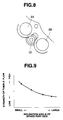
- Fig. 9 depicts a tendency that the tumble flow is enhanced as the inclination angle of the axis of intake port relative to the bottom flat surface B of the cylinder head 1 increases.
- the graph of Fig. 9 was obtained by conducting experiments on a cylinder direct injection spark-ignition engine similar to that shown in Figs. 1 to 7 with the exception that the axis of the intake port was generally straight. In the experiments, the inclination angle of axis of the intake port was varied to measure strength of the tumble flow.
- combustion speed of air-fuel mixture inside the cylinder C can be effectively increased thereby improving combustion performance of the engine E.
- the tumble stream inside the cylinder C can be sufficiently enhanced.
- the upstream-side section 5b of the intake port 5A, 5B takes the high port construction, a sufficient length of the intake port 5A, 5B can be ensured while ensuring a sufficient length of the intake air passage of the intake pipe or intake manifold 19 merely by gently bending the intake pipe 19 within the limited space LS in the automotive vehicle.
- the intake pipe 19 connected to the intake port is first upwardly extended and then gently bent downwardly gradually and smoothly with a relatively large radius of curvature, thus ensuring a sufficient length of the intake air passage in the intake pipe 19 within the limited space LS in the automotive vehicle.
- the upstream-side section 5b takes the low port construction as same as the downstream-side section 5a.
- the intake pipe 19 will be bent in a shape indicated by a dotted curve 19' in Fig. 6, so that the intake air passage inside the intake pipe is shortened as compared with that in case where the upstream-side section 5b takes the high port construction.
- the upstream-side section 5b is directed to separate from the fuel injector valve accommodating hole 18 in which the fuel injector valve 10 is to be accommodated, so that layout and machining of the fuel injector valve accommodating hole 18 can be facilitated.
- the upstream-side section 5b takes the low port construction.
- the upstream-side section 5b is directed to approach the fuel injector valve accommodating hole 18 so that they interfere with each other, thus making difficult layout and machining of the fuel injector valve accommodating hole 18, as shown in Fig. 8 which is an imaginary figure.
Landscapes
- Engineering & Computer Science (AREA)
- Chemical & Material Sciences (AREA)
- Combustion & Propulsion (AREA)
- Mechanical Engineering (AREA)
- General Engineering & Computer Science (AREA)
- Combustion Methods Of Internal-Combustion Engines (AREA)
- Cylinder Crankcases Of Internal Combustion Engines (AREA)
Applications Claiming Priority (3)
| Application Number | Priority Date | Filing Date | Title |
|---|---|---|---|
| JP13710197A JP3783747B2 (ja) | 1997-05-27 | 1997-05-27 | 内燃機関 |
| JP13710197 | 1997-05-27 | ||
| JP137101/97 | 1997-05-27 |
Publications (3)
| Publication Number | Publication Date |
|---|---|
| EP0881369A2 true EP0881369A2 (fr) | 1998-12-02 |
| EP0881369A3 EP0881369A3 (fr) | 1999-06-02 |
| EP0881369B1 EP0881369B1 (fr) | 2003-04-16 |
Family
ID=15190892
Family Applications (1)
| Application Number | Title | Priority Date | Filing Date |
|---|---|---|---|
| EP98109547A Expired - Lifetime EP0881369B1 (fr) | 1997-05-27 | 1998-05-26 | Moteur à combustion interne |
Country Status (5)
| Country | Link |
|---|---|
| US (1) | US5913297A (fr) |
| EP (1) | EP0881369B1 (fr) |
| JP (1) | JP3783747B2 (fr) |
| KR (1) | KR100302435B1 (fr) |
| DE (1) | DE69813375T2 (fr) |
Cited By (2)
| Publication number | Priority date | Publication date | Assignee | Title |
|---|---|---|---|---|
| WO1999065286A3 (fr) * | 1998-06-18 | 2000-03-30 | Fev Motorentech Gmbh | Moteur a combustion interne a pistons et a allumage commande, avec injection directe de carburant |
| EP1008734A1 (fr) * | 1998-12-10 | 2000-06-14 | Mazda Motor Corporation | Moteur à injection directe et à allumage commandé |
Families Citing this family (9)
| Publication number | Priority date | Publication date | Assignee | Title |
|---|---|---|---|---|
| SE519767C2 (sv) * | 1997-11-26 | 2003-04-08 | Volvo Car Corp | Förbränningssystem |
| FR2776708B1 (fr) * | 1998-03-26 | 2000-04-28 | Inst Francais Du Petrole | Nouveau moteur a combustion interne a quatre temps, allumage commande et injection directe |
| EP0953758B1 (fr) * | 1998-04-21 | 2003-10-08 | Ford Global Technologies, Inc., A subsidiary of Ford Motor Company | Culasse |
| JP3939864B2 (ja) * | 1998-08-27 | 2007-07-04 | ヤマハ発動機株式会社 | 筒内噴射式エンジン |
| JP2002295260A (ja) * | 2001-03-30 | 2002-10-09 | Mazda Motor Corp | 火花点火式直噴エンジン |
| US7137380B1 (en) * | 2005-08-05 | 2006-11-21 | Yamaha Hatsudoki Kabushiki Kaisha | Internal combustion engine with ignition plug and vehicle provided with the same |
| US20170211508A1 (en) * | 2014-06-30 | 2017-07-27 | Cummins Inc. | System and method for valve size ratio and igniter placement |
| US10711708B2 (en) * | 2017-08-25 | 2020-07-14 | Mazda Motor Corporation | Control device for engine |
| AT526350B1 (de) * | 2022-08-08 | 2024-02-15 | Avl List Gmbh | Brennkraftmaschine mit einem Top-Down-Kühlkonzept |
Citations (1)
| Publication number | Priority date | Publication date | Assignee | Title |
|---|---|---|---|---|
| JPH09137101A (ja) | 1995-11-15 | 1997-05-27 | Brother Ind Ltd | 記録用水性黒色インク及びインクジェット記録方法 |
Family Cites Families (12)
| Publication number | Priority date | Publication date | Assignee | Title |
|---|---|---|---|---|
| JPS6081458A (ja) * | 1983-10-12 | 1985-05-09 | Yamaha Motor Co Ltd | エンジンの吸気装置 |
| JPH07101008B2 (ja) * | 1986-01-14 | 1995-11-01 | ヤマハ発動機株式会社 | 多気筒エンジンの吸気装置 |
| JPH0672549B2 (ja) * | 1986-04-18 | 1994-09-14 | マツダ株式会社 | V型6気筒エンジン |
| US4805569A (en) * | 1987-02-13 | 1989-02-21 | Mazda Motor Corporation | Intake system for an engine |
| FR2615905B1 (fr) * | 1987-05-29 | 1989-09-15 | Renault | Culasse multisoupapes pour moteur a combustion interne |
| US5115774A (en) * | 1990-12-26 | 1992-05-26 | Toyota Jidosha Kabushiki Kaisha | Internal combustion engine |
| EP0500123B1 (fr) * | 1991-02-21 | 1995-09-27 | Yamaha Hatsudoki Kabushiki Kaisha | Système d'aspiration d'un moteur à combustion interne |
| JP2531322B2 (ja) * | 1991-09-13 | 1996-09-04 | トヨタ自動車株式会社 | 内燃機関 |
| JP2871220B2 (ja) * | 1991-09-20 | 1999-03-17 | トヨタ自動車株式会社 | 筒内噴射式内燃機関 |
| JP3152267B2 (ja) * | 1993-06-24 | 2001-04-03 | 日産自動車株式会社 | 車両のドア構造 |
| JP3300910B2 (ja) * | 1994-02-04 | 2002-07-08 | マツダ株式会社 | 直噴式ディーゼルエンジン |
| JP2982682B2 (ja) * | 1996-02-29 | 1999-11-29 | 三菱自動車工業株式会社 | 内燃機関 |
-
1997
- 1997-05-27 JP JP13710197A patent/JP3783747B2/ja not_active Expired - Lifetime
-
1998
- 1998-05-26 EP EP98109547A patent/EP0881369B1/fr not_active Expired - Lifetime
- 1998-05-26 DE DE69813375T patent/DE69813375T2/de not_active Expired - Lifetime
- 1998-05-26 US US09/084,116 patent/US5913297A/en not_active Expired - Lifetime
- 1998-05-27 KR KR1019980019200A patent/KR100302435B1/ko not_active IP Right Cessation
Patent Citations (1)
| Publication number | Priority date | Publication date | Assignee | Title |
|---|---|---|---|---|
| JPH09137101A (ja) | 1995-11-15 | 1997-05-27 | Brother Ind Ltd | 記録用水性黒色インク及びインクジェット記録方法 |
Cited By (4)
| Publication number | Priority date | Publication date | Assignee | Title |
|---|---|---|---|---|
| WO1999065286A3 (fr) * | 1998-06-18 | 2000-03-30 | Fev Motorentech Gmbh | Moteur a combustion interne a pistons et a allumage commande, avec injection directe de carburant |
| US6325042B1 (en) | 1998-06-18 | 2001-12-04 | Fev Motorentechnik Gmbh | Spark-ignition piston combustion engine with direct fuel injection |
| EP1008734A1 (fr) * | 1998-12-10 | 2000-06-14 | Mazda Motor Corporation | Moteur à injection directe et à allumage commandé |
| US6311665B1 (en) | 1998-12-10 | 2001-11-06 | Mazda Motor Corporation | Direct injection engine |
Also Published As
| Publication number | Publication date |
|---|---|
| KR19980087412A (ko) | 1998-12-05 |
| JPH10325354A (ja) | 1998-12-08 |
| DE69813375T2 (de) | 2004-03-04 |
| US5913297A (en) | 1999-06-22 |
| DE69813375D1 (de) | 2003-05-22 |
| JP3783747B2 (ja) | 2006-06-07 |
| EP0881369B1 (fr) | 2003-04-16 |
| EP0881369A3 (fr) | 1999-06-02 |
| KR100302435B1 (ko) | 2001-10-19 |
Similar Documents
| Publication | Publication Date | Title |
|---|---|---|
| US6209514B1 (en) | Direct injection gasoline engine | |
| EP0666409B1 (fr) | Moteur diesel à injection directe | |
| US6615789B2 (en) | Piston for internal combustion engines | |
| JP3733721B2 (ja) | 直噴火花点火式内燃機関 | |
| US5913297A (en) | Internal combustion engine | |
| US5915353A (en) | Cylinder direct injection spark-ignition engine | |
| US7047934B1 (en) | Fuel injection type internal combustion engine and vehicle provided with the same | |
| US6006719A (en) | Cylinder direct injection spark-ignition engine | |
| US6155229A (en) | Charge motion control valve in upper intake manifold | |
| CN110431292A (zh) | 火花点火式内燃机 | |
| JPH0979038A (ja) | 筒内噴射型内燃機関及び筒内噴射型内燃機関用ピストン | |
| JP3777660B2 (ja) | 筒内直接噴射式火花点火内燃機関 | |
| EP0945611A2 (fr) | Moteur à combustion interne du type à injection directe | |
| JP3644329B2 (ja) | 筒内噴射型内燃機関 | |
| JPH11324681A (ja) | 直接噴射火花点火4ストロ―ク内燃エンジン | |
| JP3591141B2 (ja) | 筒内直接噴射式火花点火内燃機関 | |
| JPH10238352A (ja) | 筒内噴射式エンジンの燃焼室構造 | |
| JP3146936B2 (ja) | 筒内噴射型内燃機関 | |
| JP3711699B2 (ja) | 直噴火花点火式内燃機関 | |
| KR100303979B1 (ko) | 3밸브의직분식가솔린엔진 | |
| JPH109050A (ja) | 直接筒内噴射式火花点火機関 | |
| JP2699722B2 (ja) | 成層燃焼型内燃エンジン | |
| US6082327A (en) | Direct-injection spark-ignition internal-combustion engine | |
| JP2022136396A (ja) | エンジンの燃焼室構造 | |
| JP4198037B2 (ja) | 内燃機関 |
Legal Events
| Date | Code | Title | Description |
|---|---|---|---|
| PUAI | Public reference made under article 153(3) epc to a published international application that has entered the european phase |
Free format text: ORIGINAL CODE: 0009012 |
|
| 17P | Request for examination filed |
Effective date: 19980526 |
|
| AK | Designated contracting states |
Kind code of ref document: A2 Designated state(s): DE FR GB |
|
| AX | Request for extension of the european patent |
Free format text: AL;LT;LV;MK;RO;SI |
|
| PUAL | Search report despatched |
Free format text: ORIGINAL CODE: 0009013 |
|
| AK | Designated contracting states |
Kind code of ref document: A3 Designated state(s): AT BE CH CY DE DK ES FI FR GB GR IE IT LI LU MC NL PT SE |
|
| AX | Request for extension of the european patent |
Free format text: AL;LT;LV;MK;RO;SI |
|
| AKX | Designation fees paid |
Free format text: DE FR GB |
|
| 17Q | First examination report despatched |
Effective date: 20020122 |
|
| GRAH | Despatch of communication of intention to grant a patent |
Free format text: ORIGINAL CODE: EPIDOS IGRA |
|
| GRAH | Despatch of communication of intention to grant a patent |
Free format text: ORIGINAL CODE: EPIDOS IGRA |
|
| GRAA | (expected) grant |
Free format text: ORIGINAL CODE: 0009210 |
|
| AK | Designated contracting states |
Designated state(s): DE FR GB |
|
| REG | Reference to a national code |
Ref country code: GB Ref legal event code: FG4D |
|
| REF | Corresponds to: |
Ref document number: 69813375 Country of ref document: DE Date of ref document: 20030522 Kind code of ref document: P |
|
| ET | Fr: translation filed | ||
| PLBE | No opposition filed within time limit |
Free format text: ORIGINAL CODE: 0009261 |
|
| STAA | Information on the status of an ep patent application or granted ep patent |
Free format text: STATUS: NO OPPOSITION FILED WITHIN TIME LIMIT |
|
| 26N | No opposition filed |
Effective date: 20040119 |
|
| REG | Reference to a national code |
Ref country code: FR Ref legal event code: PLFP Year of fee payment: 19 |
|
| REG | Reference to a national code |
Ref country code: FR Ref legal event code: PLFP Year of fee payment: 20 |
|
| PGFP | Annual fee paid to national office [announced via postgrant information from national office to epo] |
Ref country code: GB Payment date: 20170524 Year of fee payment: 20 Ref country code: FR Payment date: 20170413 Year of fee payment: 20 Ref country code: DE Payment date: 20170523 Year of fee payment: 20 |
|
| REG | Reference to a national code |
Ref country code: DE Ref legal event code: R071 Ref document number: 69813375 Country of ref document: DE |
|
| REG | Reference to a national code |
Ref country code: GB Ref legal event code: PE20 Expiry date: 20180525 |
|
| PG25 | Lapsed in a contracting state [announced via postgrant information from national office to epo] |
Ref country code: GB Free format text: LAPSE BECAUSE OF EXPIRATION OF PROTECTION Effective date: 20180525 |