EP0881033A1 - Method and apparatus for supplying and separating recovering liquid coolant for cutting machines and grinding machines - Google Patents
Method and apparatus for supplying and separating recovering liquid coolant for cutting machines and grinding machines Download PDFInfo
- Publication number
- EP0881033A1 EP0881033A1 EP97902667A EP97902667A EP0881033A1 EP 0881033 A1 EP0881033 A1 EP 0881033A1 EP 97902667 A EP97902667 A EP 97902667A EP 97902667 A EP97902667 A EP 97902667A EP 0881033 A1 EP0881033 A1 EP 0881033A1
- Authority
- EP
- European Patent Office
- Prior art keywords
- coolant liquid
- nozzle
- air bubbles
- tank
- liquid
- Prior art date
- Legal status (The legal status is an assumption and is not a legal conclusion. Google has not performed a legal analysis and makes no representation as to the accuracy of the status listed.)
- Granted
Links
- 239000007788 liquid Substances 0.000 title claims abstract description 196
- 239000002826 coolant Substances 0.000 title claims abstract description 180
- 238000005520 cutting process Methods 0.000 title claims abstract description 45
- 238000000227 grinding Methods 0.000 title claims abstract description 27
- 238000000034 method Methods 0.000 title claims abstract description 19
- 238000003754 machining Methods 0.000 claims abstract description 42
- 238000003801 milling Methods 0.000 claims abstract description 21
- 238000001816 cooling Methods 0.000 claims abstract description 14
- 238000005461 lubrication Methods 0.000 claims abstract description 10
- 238000011084 recovery Methods 0.000 claims abstract description 8
- 239000002245 particle Substances 0.000 claims abstract description 5
- 230000002093 peripheral effect Effects 0.000 claims description 23
- 238000004891 communication Methods 0.000 claims description 18
- 238000011144 upstream manufacturing Methods 0.000 claims description 7
- 238000007599 discharging Methods 0.000 claims description 6
- 239000013013 elastic material Substances 0.000 claims description 4
- 239000007791 liquid phase Substances 0.000 claims description 4
- 238000005192 partition Methods 0.000 claims description 4
- 238000007790 scraping Methods 0.000 claims description 4
- 230000015572 biosynthetic process Effects 0.000 claims description 3
- 239000012535 impurity Substances 0.000 claims description 2
- 230000001174 ascending effect Effects 0.000 claims 2
- 238000010438 heat treatment Methods 0.000 claims 1
- 239000003921 oil Substances 0.000 description 15
- 230000000694 effects Effects 0.000 description 11
- 238000010276 construction Methods 0.000 description 10
- 238000009434 installation Methods 0.000 description 8
- 230000001050 lubricating effect Effects 0.000 description 5
- 230000036961 partial effect Effects 0.000 description 5
- XEEYBQQBJWHFJM-UHFFFAOYSA-N Iron Chemical compound [Fe] XEEYBQQBJWHFJM-UHFFFAOYSA-N 0.000 description 4
- 239000003795 chemical substances by application Substances 0.000 description 4
- 230000009172 bursting Effects 0.000 description 3
- 238000004140 cleaning Methods 0.000 description 3
- 230000007423 decrease Effects 0.000 description 3
- 239000010419 fine particle Substances 0.000 description 3
- XLYOFNOQVPJJNP-UHFFFAOYSA-N water Substances O XLYOFNOQVPJJNP-UHFFFAOYSA-N 0.000 description 3
- 239000000654 additive Substances 0.000 description 2
- 230000000996 additive effect Effects 0.000 description 2
- 230000009193 crawling Effects 0.000 description 2
- 238000003912 environmental pollution Methods 0.000 description 2
- 229910052742 iron Inorganic materials 0.000 description 2
- 239000010410 layer Substances 0.000 description 2
- 238000002156 mixing Methods 0.000 description 2
- 239000004033 plastic Substances 0.000 description 2
- 238000000926 separation method Methods 0.000 description 2
- 239000000758 substrate Substances 0.000 description 2
- 230000001052 transient effect Effects 0.000 description 2
- 230000001133 acceleration Effects 0.000 description 1
- 239000003463 adsorbent Substances 0.000 description 1
- 239000000110 cooling liquid Substances 0.000 description 1
- 239000010730 cutting oil Substances 0.000 description 1
- 230000003247 decreasing effect Effects 0.000 description 1
- 238000010790 dilution Methods 0.000 description 1
- 239000012895 dilution Substances 0.000 description 1
- 230000001747 exhibiting effect Effects 0.000 description 1
- 244000144992 flock Species 0.000 description 1
- 239000012634 fragment Substances 0.000 description 1
- 238000011835 investigation Methods 0.000 description 1
- JEIPFZHSYJVQDO-UHFFFAOYSA-N iron(III) oxide Inorganic materials O=[Fe]O[Fe]=O JEIPFZHSYJVQDO-UHFFFAOYSA-N 0.000 description 1
- RYZCLUQMCYZBJQ-UHFFFAOYSA-H lead(2+);dicarbonate;dihydroxide Chemical compound [OH-].[OH-].[Pb+2].[Pb+2].[Pb+2].[O-]C([O-])=O.[O-]C([O-])=O RYZCLUQMCYZBJQ-UHFFFAOYSA-H 0.000 description 1
- 239000000314 lubricant Substances 0.000 description 1
- 239000002184 metal Substances 0.000 description 1
- 229910052751 metal Inorganic materials 0.000 description 1
- 239000003595 mist Substances 0.000 description 1
- 239000012071 phase Substances 0.000 description 1
- 230000002265 prevention Effects 0.000 description 1
- 230000003449 preventive effect Effects 0.000 description 1
- 238000010791 quenching Methods 0.000 description 1
- 230000000171 quenching effect Effects 0.000 description 1
- 238000004064 recycling Methods 0.000 description 1
- 230000002829 reductive effect Effects 0.000 description 1
- 239000013049 sediment Substances 0.000 description 1
- 230000035939 shock Effects 0.000 description 1
- 238000004904 shortening Methods 0.000 description 1
- 239000000779 smoke Substances 0.000 description 1
- 239000007787 solid Substances 0.000 description 1
- 239000004575 stone Substances 0.000 description 1
- 239000000126 substance Substances 0.000 description 1
- 239000002344 surface layer Substances 0.000 description 1
- 238000009834 vaporization Methods 0.000 description 1
- 230000008016 vaporization Effects 0.000 description 1
- 230000003313 weakening effect Effects 0.000 description 1
Images







Classifications
-
- B—PERFORMING OPERATIONS; TRANSPORTING
- B23—MACHINE TOOLS; METAL-WORKING NOT OTHERWISE PROVIDED FOR
- B23Q—DETAILS, COMPONENTS, OR ACCESSORIES FOR MACHINE TOOLS, e.g. ARRANGEMENTS FOR COPYING OR CONTROLLING; MACHINE TOOLS IN GENERAL CHARACTERISED BY THE CONSTRUCTION OF PARTICULAR DETAILS OR COMPONENTS; COMBINATIONS OR ASSOCIATIONS OF METAL-WORKING MACHINES, NOT DIRECTED TO A PARTICULAR RESULT
- B23Q11/00—Accessories fitted to machine tools for keeping tools or parts of the machine in good working condition or for cooling work; Safety devices specially combined with or arranged in, or specially adapted for use in connection with, machine tools
- B23Q11/10—Arrangements for cooling or lubricating tools or work
-
- B—PERFORMING OPERATIONS; TRANSPORTING
- B23—MACHINE TOOLS; METAL-WORKING NOT OTHERWISE PROVIDED FOR
- B23Q—DETAILS, COMPONENTS, OR ACCESSORIES FOR MACHINE TOOLS, e.g. ARRANGEMENTS FOR COPYING OR CONTROLLING; MACHINE TOOLS IN GENERAL CHARACTERISED BY THE CONSTRUCTION OF PARTICULAR DETAILS OR COMPONENTS; COMBINATIONS OR ASSOCIATIONS OF METAL-WORKING MACHINES, NOT DIRECTED TO A PARTICULAR RESULT
- B23Q11/00—Accessories fitted to machine tools for keeping tools or parts of the machine in good working condition or for cooling work; Safety devices specially combined with or arranged in, or specially adapted for use in connection with, machine tools
- B23Q11/10—Arrangements for cooling or lubricating tools or work
- B23Q11/1069—Filtration systems specially adapted for cutting liquids
-
- B—PERFORMING OPERATIONS; TRANSPORTING
- B01—PHYSICAL OR CHEMICAL PROCESSES OR APPARATUS IN GENERAL
- B01D—SEPARATION
- B01D17/00—Separation of liquids, not provided for elsewhere, e.g. by thermal diffusion
-
- B—PERFORMING OPERATIONS; TRANSPORTING
- B01—PHYSICAL OR CHEMICAL PROCESSES OR APPARATUS IN GENERAL
- B01D—SEPARATION
- B01D17/00—Separation of liquids, not provided for elsewhere, e.g. by thermal diffusion
- B01D17/02—Separation of non-miscible liquids
- B01D17/0205—Separation of non-miscible liquids by gas bubbles or moving solids
-
- B—PERFORMING OPERATIONS; TRANSPORTING
- B01—PHYSICAL OR CHEMICAL PROCESSES OR APPARATUS IN GENERAL
- B01D—SEPARATION
- B01D17/00—Separation of liquids, not provided for elsewhere, e.g. by thermal diffusion
- B01D17/02—Separation of non-miscible liquids
- B01D17/0208—Separation of non-miscible liquids by sedimentation
-
- B—PERFORMING OPERATIONS; TRANSPORTING
- B01—PHYSICAL OR CHEMICAL PROCESSES OR APPARATUS IN GENERAL
- B01D—SEPARATION
- B01D17/00—Separation of liquids, not provided for elsewhere, e.g. by thermal diffusion
- B01D17/02—Separation of non-miscible liquids
- B01D17/0208—Separation of non-miscible liquids by sedimentation
- B01D17/0211—Separation of non-miscible liquids by sedimentation with baffles
-
- B—PERFORMING OPERATIONS; TRANSPORTING
- B01—PHYSICAL OR CHEMICAL PROCESSES OR APPARATUS IN GENERAL
- B01D—SEPARATION
- B01D17/00—Separation of liquids, not provided for elsewhere, e.g. by thermal diffusion
- B01D17/02—Separation of non-miscible liquids
- B01D17/0208—Separation of non-miscible liquids by sedimentation
- B01D17/0214—Separation of non-miscible liquids by sedimentation with removal of one of the phases
-
- B—PERFORMING OPERATIONS; TRANSPORTING
- B01—PHYSICAL OR CHEMICAL PROCESSES OR APPARATUS IN GENERAL
- B01D—SEPARATION
- B01D17/00—Separation of liquids, not provided for elsewhere, e.g. by thermal diffusion
- B01D17/02—Separation of non-miscible liquids
- B01D17/04—Breaking emulsions
- B01D17/045—Breaking emulsions with coalescers
-
- B—PERFORMING OPERATIONS; TRANSPORTING
- B01—PHYSICAL OR CHEMICAL PROCESSES OR APPARATUS IN GENERAL
- B01D—SEPARATION
- B01D21/00—Separation of suspended solid particles from liquids by sedimentation
- B01D21/003—Sedimentation tanks provided with a plurality of compartments separated by a partition wall
-
- B—PERFORMING OPERATIONS; TRANSPORTING
- B01—PHYSICAL OR CHEMICAL PROCESSES OR APPARATUS IN GENERAL
- B01D—SEPARATION
- B01D21/00—Separation of suspended solid particles from liquids by sedimentation
- B01D21/0039—Settling tanks provided with contact surfaces, e.g. baffles, particles
- B01D21/0042—Baffles or guide plates
-
- B—PERFORMING OPERATIONS; TRANSPORTING
- B01—PHYSICAL OR CHEMICAL PROCESSES OR APPARATUS IN GENERAL
- B01D—SEPARATION
- B01D21/00—Separation of suspended solid particles from liquids by sedimentation
- B01D21/009—Heating or cooling mechanisms specially adapted for settling tanks
-
- B—PERFORMING OPERATIONS; TRANSPORTING
- B01—PHYSICAL OR CHEMICAL PROCESSES OR APPARATUS IN GENERAL
- B01D—SEPARATION
- B01D21/00—Separation of suspended solid particles from liquids by sedimentation
- B01D21/02—Settling tanks with single outlets for the separated liquid
-
- B—PERFORMING OPERATIONS; TRANSPORTING
- B01—PHYSICAL OR CHEMICAL PROCESSES OR APPARATUS IN GENERAL
- B01D—SEPARATION
- B01D21/00—Separation of suspended solid particles from liquids by sedimentation
- B01D21/24—Feed or discharge mechanisms for settling tanks
- B01D21/245—Discharge mechanisms for the sediments
- B01D21/2455—Conveyor belts
-
- B—PERFORMING OPERATIONS; TRANSPORTING
- B01—PHYSICAL OR CHEMICAL PROCESSES OR APPARATUS IN GENERAL
- B01D—SEPARATION
- B01D21/00—Separation of suspended solid particles from liquids by sedimentation
- B01D21/24—Feed or discharge mechanisms for settling tanks
- B01D21/2488—Feed or discharge mechanisms for settling tanks bringing about a partial recirculation of the liquid, e.g. for introducing chemical aids
-
- B—PERFORMING OPERATIONS; TRANSPORTING
- B01—PHYSICAL OR CHEMICAL PROCESSES OR APPARATUS IN GENERAL
- B01D—SEPARATION
- B01D21/00—Separation of suspended solid particles from liquids by sedimentation
- B01D21/28—Mechanical auxiliary equipment for acceleration of sedimentation, e.g. by vibrators or the like
- B01D21/283—Settling tanks provided with vibrators
-
- B—PERFORMING OPERATIONS; TRANSPORTING
- B03—SEPARATION OF SOLID MATERIALS USING LIQUIDS OR USING PNEUMATIC TABLES OR JIGS; MAGNETIC OR ELECTROSTATIC SEPARATION OF SOLID MATERIALS FROM SOLID MATERIALS OR FLUIDS; SEPARATION BY HIGH-VOLTAGE ELECTRIC FIELDS
- B03D—FLOTATION; DIFFERENTIAL SEDIMENTATION
- B03D1/00—Flotation
- B03D1/14—Flotation machines
- B03D1/1418—Flotation machines using centrifugal forces
-
- B—PERFORMING OPERATIONS; TRANSPORTING
- B03—SEPARATION OF SOLID MATERIALS USING LIQUIDS OR USING PNEUMATIC TABLES OR JIGS; MAGNETIC OR ELECTROSTATIC SEPARATION OF SOLID MATERIALS FROM SOLID MATERIALS OR FLUIDS; SEPARATION BY HIGH-VOLTAGE ELECTRIC FIELDS
- B03D—FLOTATION; DIFFERENTIAL SEDIMENTATION
- B03D1/00—Flotation
- B03D1/14—Flotation machines
- B03D1/1443—Feed or discharge mechanisms for flotation tanks
- B03D1/1456—Feed mechanisms for the slurry
-
- B—PERFORMING OPERATIONS; TRANSPORTING
- B03—SEPARATION OF SOLID MATERIALS USING LIQUIDS OR USING PNEUMATIC TABLES OR JIGS; MAGNETIC OR ELECTROSTATIC SEPARATION OF SOLID MATERIALS FROM SOLID MATERIALS OR FLUIDS; SEPARATION BY HIGH-VOLTAGE ELECTRIC FIELDS
- B03D—FLOTATION; DIFFERENTIAL SEDIMENTATION
- B03D1/00—Flotation
- B03D1/14—Flotation machines
- B03D1/1443—Feed or discharge mechanisms for flotation tanks
- B03D1/1462—Discharge mechanisms for the froth
-
- B—PERFORMING OPERATIONS; TRANSPORTING
- B03—SEPARATION OF SOLID MATERIALS USING LIQUIDS OR USING PNEUMATIC TABLES OR JIGS; MAGNETIC OR ELECTROSTATIC SEPARATION OF SOLID MATERIALS FROM SOLID MATERIALS OR FLUIDS; SEPARATION BY HIGH-VOLTAGE ELECTRIC FIELDS
- B03D—FLOTATION; DIFFERENTIAL SEDIMENTATION
- B03D1/00—Flotation
- B03D1/14—Flotation machines
- B03D1/16—Flotation machines with impellers; Subaeration machines
-
- B—PERFORMING OPERATIONS; TRANSPORTING
- B03—SEPARATION OF SOLID MATERIALS USING LIQUIDS OR USING PNEUMATIC TABLES OR JIGS; MAGNETIC OR ELECTROSTATIC SEPARATION OF SOLID MATERIALS FROM SOLID MATERIALS OR FLUIDS; SEPARATION BY HIGH-VOLTAGE ELECTRIC FIELDS
- B03D—FLOTATION; DIFFERENTIAL SEDIMENTATION
- B03D1/00—Flotation
- B03D1/14—Flotation machines
- B03D1/24—Pneumatic
- B03D1/247—Mixing gas and slurry in a device separate from the flotation tank, i.e. reactor-separator type
-
- B—PERFORMING OPERATIONS; TRANSPORTING
- B23—MACHINE TOOLS; METAL-WORKING NOT OTHERWISE PROVIDED FOR
- B23Q—DETAILS, COMPONENTS, OR ACCESSORIES FOR MACHINE TOOLS, e.g. ARRANGEMENTS FOR COPYING OR CONTROLLING; MACHINE TOOLS IN GENERAL CHARACTERISED BY THE CONSTRUCTION OF PARTICULAR DETAILS OR COMPONENTS; COMBINATIONS OR ASSOCIATIONS OF METAL-WORKING MACHINES, NOT DIRECTED TO A PARTICULAR RESULT
- B23Q11/00—Accessories fitted to machine tools for keeping tools or parts of the machine in good working condition or for cooling work; Safety devices specially combined with or arranged in, or specially adapted for use in connection with, machine tools
-
- B—PERFORMING OPERATIONS; TRANSPORTING
- B23—MACHINE TOOLS; METAL-WORKING NOT OTHERWISE PROVIDED FOR
- B23Q—DETAILS, COMPONENTS, OR ACCESSORIES FOR MACHINE TOOLS, e.g. ARRANGEMENTS FOR COPYING OR CONTROLLING; MACHINE TOOLS IN GENERAL CHARACTERISED BY THE CONSTRUCTION OF PARTICULAR DETAILS OR COMPONENTS; COMBINATIONS OR ASSOCIATIONS OF METAL-WORKING MACHINES, NOT DIRECTED TO A PARTICULAR RESULT
- B23Q11/00—Accessories fitted to machine tools for keeping tools or parts of the machine in good working condition or for cooling work; Safety devices specially combined with or arranged in, or specially adapted for use in connection with, machine tools
- B23Q11/0042—Devices for removing chips
- B23Q11/0053—Devices for removing chips using the gravity force
-
- B—PERFORMING OPERATIONS; TRANSPORTING
- B23—MACHINE TOOLS; METAL-WORKING NOT OTHERWISE PROVIDED FOR
- B23Q—DETAILS, COMPONENTS, OR ACCESSORIES FOR MACHINE TOOLS, e.g. ARRANGEMENTS FOR COPYING OR CONTROLLING; MACHINE TOOLS IN GENERAL CHARACTERISED BY THE CONSTRUCTION OF PARTICULAR DETAILS OR COMPONENTS; COMBINATIONS OR ASSOCIATIONS OF METAL-WORKING MACHINES, NOT DIRECTED TO A PARTICULAR RESULT
- B23Q11/00—Accessories fitted to machine tools for keeping tools or parts of the machine in good working condition or for cooling work; Safety devices specially combined with or arranged in, or specially adapted for use in connection with, machine tools
- B23Q11/10—Arrangements for cooling or lubricating tools or work
- B23Q11/1038—Arrangements for cooling or lubricating tools or work using cutting liquids with special characteristics, e.g. flow rate, quality
- B23Q11/1061—Arrangements for cooling or lubricating tools or work using cutting liquids with special characteristics, e.g. flow rate, quality using cutting liquids with specially selected composition or state of aggregation
-
- B—PERFORMING OPERATIONS; TRANSPORTING
- B01—PHYSICAL OR CHEMICAL PROCESSES OR APPARATUS IN GENERAL
- B01D—SEPARATION
- B01D2221/00—Applications of separation devices
- B01D2221/14—Separation devices for workshops, car or semiconductor industry, e.g. for separating chips and other machining residues
-
- B—PERFORMING OPERATIONS; TRANSPORTING
- B03—SEPARATION OF SOLID MATERIALS USING LIQUIDS OR USING PNEUMATIC TABLES OR JIGS; MAGNETIC OR ELECTROSTATIC SEPARATION OF SOLID MATERIALS FROM SOLID MATERIALS OR FLUIDS; SEPARATION BY HIGH-VOLTAGE ELECTRIC FIELDS
- B03D—FLOTATION; DIFFERENTIAL SEDIMENTATION
- B03D1/00—Flotation
- B03D1/02—Froth-flotation processes
- B03D1/028—Control and monitoring of flotation processes; computer models therefor
-
- B—PERFORMING OPERATIONS; TRANSPORTING
- B03—SEPARATION OF SOLID MATERIALS USING LIQUIDS OR USING PNEUMATIC TABLES OR JIGS; MAGNETIC OR ELECTROSTATIC SEPARATION OF SOLID MATERIALS FROM SOLID MATERIALS OR FLUIDS; SEPARATION BY HIGH-VOLTAGE ELECTRIC FIELDS
- B03D—FLOTATION; DIFFERENTIAL SEDIMENTATION
- B03D1/00—Flotation
- B03D1/14—Flotation machines
- B03D1/1487—Means for cleaning or maintenance
-
- Y—GENERAL TAGGING OF NEW TECHNOLOGICAL DEVELOPMENTS; GENERAL TAGGING OF CROSS-SECTIONAL TECHNOLOGIES SPANNING OVER SEVERAL SECTIONS OF THE IPC; TECHNICAL SUBJECTS COVERED BY FORMER USPC CROSS-REFERENCE ART COLLECTIONS [XRACs] AND DIGESTS
- Y02—TECHNOLOGIES OR APPLICATIONS FOR MITIGATION OR ADAPTATION AGAINST CLIMATE CHANGE
- Y02P—CLIMATE CHANGE MITIGATION TECHNOLOGIES IN THE PRODUCTION OR PROCESSING OF GOODS
- Y02P70/00—Climate change mitigation technologies in the production process for final industrial or consumer products
- Y02P70/10—Greenhouse gas [GHG] capture, material saving, heat recovery or other energy efficient measures, e.g. motor control, characterised by manufacturing processes, e.g. for rolling metal or metal working
-
- Y—GENERAL TAGGING OF NEW TECHNOLOGICAL DEVELOPMENTS; GENERAL TAGGING OF CROSS-SECTIONAL TECHNOLOGIES SPANNING OVER SEVERAL SECTIONS OF THE IPC; TECHNICAL SUBJECTS COVERED BY FORMER USPC CROSS-REFERENCE ART COLLECTIONS [XRACs] AND DIGESTS
- Y10—TECHNICAL SUBJECTS COVERED BY FORMER USPC
- Y10S—TECHNICAL SUBJECTS COVERED BY FORMER USPC CROSS-REFERENCE ART COLLECTIONS [XRACs] AND DIGESTS
- Y10S29/00—Metal working
- Y10S29/05—Cutting fluid application and debris control
-
- Y—GENERAL TAGGING OF NEW TECHNOLOGICAL DEVELOPMENTS; GENERAL TAGGING OF CROSS-SECTIONAL TECHNOLOGIES SPANNING OVER SEVERAL SECTIONS OF THE IPC; TECHNICAL SUBJECTS COVERED BY FORMER USPC CROSS-REFERENCE ART COLLECTIONS [XRACs] AND DIGESTS
- Y10—TECHNICAL SUBJECTS COVERED BY FORMER USPC
- Y10S—TECHNICAL SUBJECTS COVERED BY FORMER USPC CROSS-REFERENCE ART COLLECTIONS [XRACs] AND DIGESTS
- Y10S29/00—Metal working
- Y10S29/077—Metal working with separator or filter
-
- Y—GENERAL TAGGING OF NEW TECHNOLOGICAL DEVELOPMENTS; GENERAL TAGGING OF CROSS-SECTIONAL TECHNOLOGIES SPANNING OVER SEVERAL SECTIONS OF THE IPC; TECHNICAL SUBJECTS COVERED BY FORMER USPC CROSS-REFERENCE ART COLLECTIONS [XRACs] AND DIGESTS
- Y10—TECHNICAL SUBJECTS COVERED BY FORMER USPC
- Y10S—TECHNICAL SUBJECTS COVERED BY FORMER USPC CROSS-REFERENCE ART COLLECTIONS [XRACs] AND DIGESTS
- Y10S82/00—Turning
- Y10S82/901—Chip removal
-
- Y—GENERAL TAGGING OF NEW TECHNOLOGICAL DEVELOPMENTS; GENERAL TAGGING OF CROSS-SECTIONAL TECHNOLOGIES SPANNING OVER SEVERAL SECTIONS OF THE IPC; TECHNICAL SUBJECTS COVERED BY FORMER USPC CROSS-REFERENCE ART COLLECTIONS [XRACs] AND DIGESTS
- Y10—TECHNICAL SUBJECTS COVERED BY FORMER USPC
- Y10T—TECHNICAL SUBJECTS COVERED BY FORMER US CLASSIFICATION
- Y10T407/00—Cutters, for shaping
- Y10T407/14—Cutters, for shaping with means to apply fluid to cutting tool
-
- Y—GENERAL TAGGING OF NEW TECHNOLOGICAL DEVELOPMENTS; GENERAL TAGGING OF CROSS-SECTIONAL TECHNOLOGIES SPANNING OVER SEVERAL SECTIONS OF THE IPC; TECHNICAL SUBJECTS COVERED BY FORMER USPC CROSS-REFERENCE ART COLLECTIONS [XRACs] AND DIGESTS
- Y10—TECHNICAL SUBJECTS COVERED BY FORMER USPC
- Y10T—TECHNICAL SUBJECTS COVERED BY FORMER US CLASSIFICATION
- Y10T408/00—Cutting by use of rotating axially moving tool
- Y10T408/44—Cutting by use of rotating axially moving tool with means to apply transient, fluent medium to work or product
-
- Y—GENERAL TAGGING OF NEW TECHNOLOGICAL DEVELOPMENTS; GENERAL TAGGING OF CROSS-SECTIONAL TECHNOLOGIES SPANNING OVER SEVERAL SECTIONS OF THE IPC; TECHNICAL SUBJECTS COVERED BY FORMER USPC CROSS-REFERENCE ART COLLECTIONS [XRACs] AND DIGESTS
- Y10—TECHNICAL SUBJECTS COVERED BY FORMER USPC
- Y10T—TECHNICAL SUBJECTS COVERED BY FORMER US CLASSIFICATION
- Y10T408/00—Cutting by use of rotating axially moving tool
- Y10T408/44—Cutting by use of rotating axially moving tool with means to apply transient, fluent medium to work or product
- Y10T408/46—Cutting by use of rotating axially moving tool with means to apply transient, fluent medium to work or product including nozzle
-
- Y—GENERAL TAGGING OF NEW TECHNOLOGICAL DEVELOPMENTS; GENERAL TAGGING OF CROSS-SECTIONAL TECHNOLOGIES SPANNING OVER SEVERAL SECTIONS OF THE IPC; TECHNICAL SUBJECTS COVERED BY FORMER USPC CROSS-REFERENCE ART COLLECTIONS [XRACs] AND DIGESTS
- Y10—TECHNICAL SUBJECTS COVERED BY FORMER USPC
- Y10T—TECHNICAL SUBJECTS COVERED BY FORMER US CLASSIFICATION
- Y10T409/00—Gear cutting, milling, or planing
- Y10T409/30—Milling
- Y10T409/303752—Process
-
- Y—GENERAL TAGGING OF NEW TECHNOLOGICAL DEVELOPMENTS; GENERAL TAGGING OF CROSS-SECTIONAL TECHNOLOGIES SPANNING OVER SEVERAL SECTIONS OF THE IPC; TECHNICAL SUBJECTS COVERED BY FORMER USPC CROSS-REFERENCE ART COLLECTIONS [XRACs] AND DIGESTS
- Y10—TECHNICAL SUBJECTS COVERED BY FORMER USPC
- Y10T—TECHNICAL SUBJECTS COVERED BY FORMER US CLASSIFICATION
- Y10T409/00—Gear cutting, milling, or planing
- Y10T409/30—Milling
- Y10T409/303976—Milling with means to control temperature or lubricate
- Y10T409/304032—Cutter or work
-
- Y—GENERAL TAGGING OF NEW TECHNOLOGICAL DEVELOPMENTS; GENERAL TAGGING OF CROSS-SECTIONAL TECHNOLOGIES SPANNING OVER SEVERAL SECTIONS OF THE IPC; TECHNICAL SUBJECTS COVERED BY FORMER USPC CROSS-REFERENCE ART COLLECTIONS [XRACs] AND DIGESTS
- Y10—TECHNICAL SUBJECTS COVERED BY FORMER USPC
- Y10T—TECHNICAL SUBJECTS COVERED BY FORMER US CLASSIFICATION
- Y10T409/00—Gear cutting, milling, or planing
- Y10T409/30—Milling
- Y10T409/304088—Milling with means to remove chip
-
- Y—GENERAL TAGGING OF NEW TECHNOLOGICAL DEVELOPMENTS; GENERAL TAGGING OF CROSS-SECTIONAL TECHNOLOGIES SPANNING OVER SEVERAL SECTIONS OF THE IPC; TECHNICAL SUBJECTS COVERED BY FORMER USPC CROSS-REFERENCE ART COLLECTIONS [XRACs] AND DIGESTS
- Y10—TECHNICAL SUBJECTS COVERED BY FORMER USPC
- Y10T—TECHNICAL SUBJECTS COVERED BY FORMER US CLASSIFICATION
- Y10T82/00—Turning
- Y10T82/10—Process of turning
Definitions
- the present invention relates to a method and apparatus for feeding a coolant liquid and separating and recovering it in a cutting machine and a grinding machine, particularly a method and apparatus for feeding a flow of coolant liquid to a region of contact between a cutter or the like and a workpiece and it also relates to a method and apparatus for automatically separating and recovering the coolant liquid subsequent to the supply thereof.
- the factor which plays a major role in shortening the processing time and minimizing the strain due to processing is to enhance contact lubrication between a cutting tool or grinding tool and a workpiece and promote dissipation of heat of friction or cooling. That is, from the standpoint that the cutting conditions can be improved by slightly weakening the surface layer, if the coolant liquid is allowed to flow in all directions into the main cutting shear region and to be adsorbed by the created macroscopic cracks or voids, this results in lowering the surface energy and preventing re-adhesion. Such effect of brittleness in the shear region is very useful in providing an increased shear angle and a decrease in the thickness of chips and also in the cutting force.
- an aspect of the present invention provides a method for feeding a coolant liquid to a cutting machine or grinding machine, which is characterized by feeding a coolant liquid, with bubbles caused to form continuously therein, for cutting or grinding operation to a region under machining, expediting the splashing of air bubbles in all directions when the air bubbles impinge on the region under machining and burst, and also expediting the entry of accelerated splashed liquid particles into a cutter/workpiece pressure contact plane, thereby improving the cooling and lubrication of said region under machining, whereby the air bubbles in the coolant liquid which has failed to reach the region under machining or which, though reaching there, has left there for the recovery channel are allowed to adhere to suspended foreign matters in said liquid, thereby expediting the surfacing of the foreign matters.
- a nozzle for this purpose is designed to spout the coolant liquid against a non-rotating circumferential region surrounding the region under machining. And I have found that in the interior of the nozzle, there is formed a particulate turbulent flow of coolant liquid and that by imparting a spiral rotation thereto, the coolant liquid which reaches the circumferential region moves, as if crawling in a whirl, to the central region including the rotating tool.
- another aspect of the invention provides a method for feeding a coolant liquid to a cutting machine or grinding machine, which is characterized by installing an annular nozzle for coolant liquid above a milling tool or grinding tool connected to a vertical main spindle so that it faces downward at a substantially coaxial position, the inner wall of said nozzle which extends to its discharge port being formed with a curved surface and a twist channel for producing a turbulent flow, whereby the coolant liquid being fed is discharged downward through said discharge port generally as a spiral flow which is a collection of particulate turbulent flows, thereby forming a cylindrical veil of spiral flow of coolant liquid which surrounds said milling tool or grinding tool and whose lower end reaches the surface of the workpiece, at least a part of said spiral flow being caused to move from the lower end of said cylindrical veil along the surface of the workpiece in a whirl toward the central region until it is fed to the region under machining which is in contact with the milling tool or grinding tool, the at least a part of said spiral flow being
- the cylindrical veil of coolant liquid itself contributes to the formation of said whirling surface flow and also serves for prevention of environmental pollution by enclosing the smoke from the scorching of oil and oil films on the workpiece surface due to cutting.
- air bubbles are caused to form in the coolant liquid being fed to said cylindrical nozzle, the effect of the whirling flow feeding a coolant liquid to the region under machining and the above-described effect brought about by air bubbles can be concurrently developed.
- the nozzle construction invented in order to use said coolant liquid feeding method forms an annular nozzle for downwardly discharging coolant liquid adapted to be installed above and coaxial with a milling tool or grinding tool connected to a vertical main spindle, said noble comprising:
- another aspect of the invention is to provide a separating and recovering apparatus for coolant liquid in a cutting machine or grinding machine for collecting a coolant liquid fed to a region under machining and separating impurities therefrom and then discharging it, said separating and recovering device comprising;
- the separation of solid fine particles is effected normally without using a large-scale device such as a centrifugal separator, and since filter means such as a paper filter is not used, there is no danger of the additive agents in the coolant liquid being removed owing to filter clogging caused by the oil content.
- the reason for the foreign matter scraping blade being opposed to the roller with a narrow clearance therebetween is to allow the oil content to deposit on the peripheral roller surface to form a deposited layer of oil content (substrate) having a thickness corresponding to said narrow clearance and thence forth allow an oil film of air bubbles adhering to chips and the like to be implanted on said substrate with ease so as to form, as it were, a colony of the same substance. Therefore, implanted foreign matters formed as every portion of the peripheral roller surface passes through the top layer of the coolant liquid is scraped by the blade as they come out above the liquid surface and reach the blade.
- another aspect of the invention provides a method of feeding a coolant liquid for a lathe, comprising the steps of positioning a nozzle above the work holding chuck of the lathe, said nozzle including a discharge port of substantially rectangular cross section and a constricted curved surface portion on its inner wall extending to said discharge port for producing a turbulent flow, and also including a loosely mounted tongue piece of rigid or elastic material crossing the section of said discharge port and projecting outward, whereby said nozzle is arranged such that a coolant liquid received through the inlet disposed upstream of said constricted curved surface portion is discharged from said discharge port as a collection of particulate turbulent flows containing air bubbles drawn into the coolant liquid as the latter passes by said tongue piece, said cross section of the discharge port of said substantially rectangular section being disposed substantially orthogonal to the plane containing the main axis of the lathe and facing obliquely downward deviated in the direction in which the workpiece projects, whereby the coolant liquid discharged from said nozzle is caused to imping
- the arrangement of the coolant liquid feeding nozzle invented to be used with said method of feeding a coolant liquid for a lathe comprises;
- the numeral 1 denotes a main tank of large capacity for storing coolant liquid
- 2 denotes a coolant pump (P1) which, in this case, is used to take in air to cause air bubbles to form in a coolant liquid and feed the liquid to an annular nozzle 3.
- the annular nozzle 3 is used to downwardly spout the coolant liquid fed from the pump P1 as a cylindrical veil 4 generally consisting of a spiral flow which is a collection of particulate turbulent flows to impinge on the surface of a workpiece 5.
- the workpiece 5 is cut on a movable table 6 by a milling tool 7 which, in this case, is a fullback cutter, and a main spindle 8 supporting the milling tool 7 passes through the annular nozzle 3.
- a milling tool 7 which, in this case, is a fullback cutter
- a main spindle 8 supporting the milling tool 7 passes through the annular nozzle 3.
- the coolant liquid discharged outside the cylindrical veil 4 sinusoidally each time its mound increases travels, together with the portion of the coolant liquid which has initially been directed outward, via the workpiece 5 and a movable table 6 to flow down, in this case, into a gutter-like outer peripheral pan 9, and is drawn, up by a second coolant pump 2' (P2) through a suction port 10, finally reaching a separating and recovering tank 11.
- P2 second coolant pump 2'
- the coolant liquid after having the foreign matters, such as oil and chips, removed therefrom is returned to said large-capacity tank 1 through a filling port 12.
- the coolant liquid supplied as a cylindrical veil 4 preferably contains lots of air bubbles due to the air take-in action of the coolant pump 2. Therefore, the coolant liquid containing lots of air bubbles which is fed to the region of contact between the milling tool 7 and the workpiece 5 undergoes centrifugal force from the rotation of the tool to a less degree due to its lower mass, a fact which makes it easier for the coolant liquid to penetrate into the tool/workpiece contact region. And in this case the splashed liquid created upon the bursting of air bubbles easily enter into the fine cracks by the action of acceleration.
- this arrangement is also superior in dissipation of heat due to bursting, and the lubricating action and heat dissipating action thereof, as described above, enhance the cutting performance of the tool and make it possible to use a sintered carbide tool to effect cutting with high feed rate.
- the cutting heat is continuously carried away by the flow of coolant liquid discharged from the region under machining.
- the effect of feeding such air bubble-containing coolant liquid is attained not only by the system of the present invention forming a whirling flow through the cylindrical veil 4 but also by a direct nozzle jet flow 13 to the cutting point as has heretofore been practiced.
- the operation for causing air bubbles to form in a coolant liquid is effected by the air take-in action of the pump 2, as described above, but besides this, it can also be effected, e.g., by making sufficiently high the head between the recovery pipe pouring port 14 and the liquid level of the tank 11 and the head between the filling port 12 at the outlet of the separating and recovering tank 11 and the liquid level of the large-capacity tank 1 to produce a pouring impact.
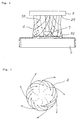
- Fig. 2 shows in detail the sectional construction of the annular nozzle 3 for coolant liquid.
- the main portion of the inner peripheral surface of the annular nozzle 3 is supported by the outer peripheral surface of a main spindle cover 15.
- the annular nozzle 3 comprises an inlet annulus 16 at the upper end, an intermediate channel annulus 17, and a nozzle annulus 19.
- the inlet annulus 16 forms an annular inlet chamber 20 to receive a supply of coolant liquid from the upper inlet 21.
- the channel annulus 17 is connected to the inlet annulus 16 such that its upper end surface defines the bottom surface of the inlet chamber 20.
- coolant liquid introducing passages 22 are defined to extend from the upper and to the lower end, thus defining an outwardly twisted channel 23 twisted in a unified direction of rotation at the lower ends of the introducing passages 22.
- a relatively large channel serving as a turbulent flow forming portion 24.
- the upper surface of the main portion of the bent annulus 18 defines the bottom surfaces of the twist channel 23 and turbulent flow forming portion 24 and, its outer end, at a position where it forms an annular discharge passage 25 between it and the outer peripheral wall of the turbulent flow forming portion 24 defines an upwardly projecting portion 26 and an inwardly turned bask portion 27.
- the inward coolant liquid flow twisted in a predetermined direction of rotation from the twist channel 23 impinges on the inner surface of the upwardly projecting portion 26 of the bent annulus and is inwardly turned back, detouring around the inwardly turned back portion 27 to bend outwardly, and finally flowing out as a collection of microscopic whirling flows or tiny turbulent flows downwardly through an annular discharge passage.
- the nozzle annulus 19 is provided with an inclined floor surface 30 which defines an inwardly and downwardly inclined nozzle space 29 between the outer wall 28 connected to the outer wall of the channel annulus 17 and the lower end surface of the bent annulus 18. Since the front end of the inclined floor surface 30 is sharply inclined downward, it follows that the coolant liquid discharged from the discharge passage thereabove is rotating and that said coolant liquid is discharged mostly as a cylindrical downward spiral flow under its own weight.
- Fig. 3 is a combination of horizontal sections showing in order the flow of coolant liquid in said annular nozzle, wherein first, at A, the coolant liquid flowing in through the inlet annulus 21 travels into one vertical introducing passage 22 to flow downward, and the coolant liquid leaving the lower end of said introducing passage 22, as shown in B-section, travels through the twist channel 23, entering the turbulent flow forming portion 24 as a counterclockwise flow in this case, and as shown at the section C, bends inwardly and outwardly from said turbulent flow forming portion 24 to reach the outer discharge passage 31 connected to the nozzle space 29, from which discharge passage 31, as shown by arrows in the section D it travels through the nozzle space 29 until it is discharged as a spiral flow moving inwardly and then downwardly, as will be understood.
- Figs. 4 and 5 are views which show in detail the state of the cylindrical veil 4 and whirling surface flow discharged from the annular nozzle.
- the coolant liquid discharged as the cylindrical veil 4 falls typically in the form of a constricted bell-shaped spiral flow as a result of its self-weight, centrifugal force and rotative speed, and in cases in which it contains a number of air bubbles, it impinges on the surface of the workpiece 5 while assuming a clouding state.
- Most of the coolant liquid impinging on the surface of the workpiece 5 travels in a whirl in the direction of the spiral rotation toward the center, covering the lower portion of the tool 7, exhibiting a mound as shown at 32 in Fig. 4.
- the coolant liquid sinusoidally flows outside the veil 4; thus, the coolant liquid contributes to the lubrication and cooling of the region of contact between the milling tool 7 and the workpiece 5 while repeating the mounding.
- the separating and recovering tank 11 for the coolant liquid is divided into sections and has a plurality (4 in this case) of sleeve bundle communication tanks 37, 38, 39 and 40 disposed between an inflow tank 34 positioned immediately below the feed port 14 and an outlet tank 36 having a discharge port 35.
- a communication port 41 having a lower edge disposed slightly above the bottom surface and an upper edge disposed slightly below the final overflow level, and the communication tanks 37 and 38 communicate with each other through a sleeve bundle 42 having a substantially honeycomb-shaped cross section (Fig. 8).
- the latter communication tank 38 and the next communication tank 39 communicate with each other again through a similar communication port 41, and the communication tank 39 and the next communication tank 40 communicate with each other through a second similar sleeve bundle 42. Further, the final communication tank 40 and the outlet tank 36 communicate with each other through a communication port 41 such as mentioned above.
- a foreign matter arresting belt conveyor 43 having a vertical front at a position opposed to the outlet of the sleeve bundle 42, the upper end of said belt conveyor being above the level of the coolant liquid surface 44 in the tank and also above the level of the upper edge 45 of the tank.
- each blade 47 and the upper ends of each roller 46 There is a slight clearance between each blade 47 and the upper ends of each roller 46, and an oil film adheres to the surface of the roller 46 until it fills said clearance and an oil film on the surface of an adhering mass of chips and air bubbles easily deposits on the first-mentioned oil film in the form of a flock or colony and is scraped off at the blade position.
- This remark is applicable also to the relation between the belt conveyor 43 and the blade 48.
- the ports for communication between the tanks 34 and 37, between the tanks 38 and 39 and between the tanks 40 and 36 serve to check a precipitatedheavy foreign matter and a normally surfacing light-weight foreign matter to prevent them from flowing into the next tank. For example, if a foreign matter reservoir 49 is disposed on the bottom of the inlet tank 34, the sediment can be removed by raising said foreign matter reservoir 49 at a suitable time.
- the sleeve bundles 42 disposed to extend through the tandem tanks 37, 38 and 39, 40 are inclined slightly upward from the downstream to the upstream side as shown in Fig. 8, and such that as the coolant liquid proceeds therethrough to the next tank, foreign matters adhering to oil films on the air bubbles and tending to float impinge on the upper surface of the sleeve and stay there, but similar foreign matters impinge on the same in succession and the latter increase in diameter until they are pushed by the liquid flow and driven into the downstream tank, where the foreign matters float on the liquid surface.
- each tank adheres to the oil film on the surface of the roller 46 and are carried to the liquid surface, whereupon they are scraped off by the blade 47.
- the foreign matters in the coolant liquid discharged from the final sleeve bundle 42 adhere to the vertical surface of the belt conveyor opposed to the outlet end of said sleeve bundle and are thereby raised above the liquid surface and then scraped off by the blade 48.
- a heater 50 disposed immediately below each sleeve bundle 42 is positioned immediately below each sleeve bundle 42 , serving as a heat source for reliably removing the adhering foreign matters in the sleeve bundle 42. This utilizes the fact that the viscosity of oil decreases with increasing temperature.
- the separating and recovering tank 11 may be heated in its entirety.
- the arrangement of said separating and recovering tank is shown by way of example only, and it is clear that the number of sleeve bundle-communicated tanks may be increased from the illustrated 4 to 6 or more and that if air bubbles are already present, only two tanks will suffice.
- the coolant liquid being recycled is maintained clean at all times, whereby the cleaning of the large-capacity tank is facilitated, prolonging the renewal period for the coolant liquid. Further, it is clear that since no use of oil adsorbent, paper filter or the like is involved, the arresting cost can be reduced.
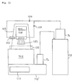
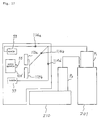
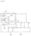
- FIGs. 10 through 12 show three installation examples embodying the basic constructional principle of the present invention.
- a first embodiment has a liquid tank arrangement different from the basic arrangement shown in Fig. 1, wherein a coolant liquid preferably containing air bubbles are fed from a coolant pump P1 installed directly on a separating and recovering tank 101 into said annular nozzle 3 and an auxiliary nozzle 102 of conventional type respectively through flow control valves 103 and 104.
- a separating and recovering section 111 is formed within a tank 110' disposed below a machine body 106, and a recovered coolant liquid drawn therefrom by a coolant pump P2 is fed to a large-capacity preparatory tank 112 and is directed to the region under machining, the rest of the arrangement being the same as i the first embodiment shown in Fig. 10.
- a separating and recovering tank 111' itself is disposed immediately below the machine body 106, with a large-capacity tank 110'' connected thereto, and a single coolant pump P1 alone is used to feed a coolant liquid, the rest of the arrangement being the same as in the embodiments shown in Figs. 10 and 11.
- Fig. 13 is a diagrammatic side view showing another arrangement for feeding a coolant liquid according to the invention.
- a coolant liquid nozzle 53 spouts a turbulent coolant liquid containing air bubbles from its lower end nozzle port of rectangular cross section over a region extending from the upper peripheral portion of a workpiece gripping chuck 55 axially to a workpiece 56 and at least a cutting tool 57.
- the coolant liquid impinging on the chuck 55, the peripheral surface of the workpiece 56 and the cutting tool 57 forms a flowing film attached to the rotating peripheral surface with the presence of its turbulent flow and air bubbles preventing the cooling liquid from being splashed, the coolant liquid being affluently fed to the region of contact between the cutting tool 57 and the workpiece 56.
- this system also, the same effect of lubricating and cooling the contact region as in the case of the nozzle shown in Figs. 1 through 5.
- the coolant liquid jet flow from the nozzle 53 impinges on the tool rest located above the cutting tool 57, so that the coolant liquid is more satisfactorily fed to said contact region.
- Figs. 14 through 16 show the construction of an embodiment of the nozzle 53.
- the configuration of the nozzle 53 shown in Fig. 13 shows the relation between a first nozzle portion 53a and a nozzle body 53b in the right-hand side of Fig. 14.
- This first nozzle portion 53a and a second nozzle portion 54c both have at their lower end corner a nozzle opening 58 whose outlet section H (Fig. 15) is substantially rectangular, through which nozzle opening a coolant liquid is spouted downward as seen in Figs. 13 through 15 (a).
- the numeral 59 denotes a vibrating element or tongue element of metal having substantial rigidity or elasticity inserted in the nozzle opening 58 is adapted to vibrate or form a flow resistance in order to cause air bubbles to form in the spouted coolant liquid during the spouting of the latter.
- This vibrating element 59 as shown in Fig. 15, is fixed only at its upper end region 60 to the wall surface of the nozzle opening 58, allowing the coolant liquid to flow therearound.
- a cross section of the nozzle opening 58 as seen from the outside is rectangular, as described above, and its interior is an inlet chamber for coolant liquid, said inlet chamber communicating with a coolant liquid receiving port 61 in the main body 53b which is integral with the first nozzle portion 53a.
- a communication port 62 leading to the receiving port 61 serves as a turbulent flow forming section is constricted to have a smaller cross section than the pertinent cross-sectional area of the inlet chamber and the receiving inlet, so that the coolant liquid flowing into the receiving port 61 passes through this turbulent flow forming section whereby it flows from the inlet chamber into the nozzle opening 58 as a collection of particulated turbulent flows.
- the turbulent flow forming section 62 as shown in Fig.
- the second nozzle portion 53c is angularly adjustable with respect to the main body portion 53b and the angle between the planes including the vibrating plates 59 of the two nozzles can be changed to adjust the spouting in such a manner as to, e.g., spout the coolant liquid at right angles against the peripheral surface of the chuck positioned below the nozzle 53 disposed at the fixed position on the machine.
- Figs. 17 through 19 show three installation examples using this second nozzle construction, wherein in each case, two nozzles 53 are installed for two tool rests, and there are channels for feeding a coolant liquid directly to these tool rests 113a and 113b, with flow control valves 114a, 114a' and 114b placed therein.
- 108' denotes a main spindle
- 201 denotes a separating and recovering tank
- 210 denotes a main tank
- 212 denotes a preparatory tank.
- the rest of the arrangement, as long as the one shown in Fig. 17 is concerned, is the same as the first embodiment concerning the first constructional principle shown in Fig. 10.
- Figs. 18 and 19 have the same nozzle channels and tool rest feeding channels as in Fig. 17, the rest of the arrangement being constructed in the same manner as in the second and third embodiments concerning the first constructional principle shown in Figs. 11 and 12.
- a 12 mm thick, 1212 mm wide, 2424 mm long, SS400 plate which was generally considered difficult to cut was successfully cut with a main spindle horse power of 15 KW/h, a cutter diameter of 200 mm, a cutting depth of 1.3 mm, a cutting rate of 500 mm/min, and a cutting feed rate of 3,000 mm/min to 5,000 mm/min.
- a tool to be used it is also possible to use a commercially available non-coat tip.
- a commercially available coated tip If a commercially available coated tip is used, a commercially available non-annealed black-skin iron plate which was 12 mm thick x 1212 mm x 2424 mm was cut with a main spindle horse power of 15 KW/h, a cutting depth of 1.7 mm, a cutting rate of 400 mm/min, and a cutting feed rate of 3,650 mm/min, and even if a fullback cutter was used, it was possible to keep down the warp to within 0.1 mm. Subsequent to the rough cutting, if the warp is removed and final finishing is effected by using a flat drag-equipped fullback cutter for finishing, it becomes possible to increase productivity.
- the coolant liquid feeding nozzle does not require adjusting even if the tool length is changed in order not to allow the coolant liquid to flow directly to the cutting point. This is very effective for a machine, like a machining center, which always uses tools of different lengths.
- the present invention in the arrangement described above, provides a method of preparing a coolant liquid containing air bubbles superior in lubrication and cooling, a nozzle feeding system for producing an affluent supply of coolant liquid to the cutting point, and a coolant liquid recycling system superior in a foreign matter separating function, thereby enabling high precision cutting or milling by feeding such coolant liquid.
- the machining rate can be increased to 1.5 - 3 times and hence the resulting economic effect is very high. Further, since a great reduction in the cutting oil cost and in the tank cleaning cost can be expected, there are provided far-reaching effects in efficiency improvement, the easing of environmental pollution, labor saving, etc. Further, as a coolant liquid, in some cases, water and a rust-preventive agent alone may be used to effect cutting.
Landscapes
- Chemical & Material Sciences (AREA)
- Chemical Kinetics & Catalysis (AREA)
- Engineering & Computer Science (AREA)
- Physics & Mathematics (AREA)
- Thermal Sciences (AREA)
- Life Sciences & Earth Sciences (AREA)
- Biotechnology (AREA)
- Mechanical Engineering (AREA)
- Fluid Mechanics (AREA)
- Auxiliary Devices For Machine Tools (AREA)
- Grinding-Machine Dressing And Accessory Apparatuses (AREA)
Abstract
The coolant liquid is discharged downward generally as a spiral flow which is a collection of particulate turbulent flows, thereby forming a cylindrical veil of coolant liquid which surrounds the milling tool or grinding tool and whose lower end reaches the surface of the workpiece, at least part of the spiral flow being caused to move from the lower end of the cylindrical veil along the surface of the workpiece in a whirl toward the central region until it is fed to the region under machining which is in contact with the milling tool or grinding tool.
Description
Claims (12)
- A method of feeding a coolant liquid in a cutting machine or grinding machine, which is characterized by feeding a coolant liquid, with air bubbles caused to form continuously therein, for cutting or grinding operation to a region under machining, expediting the splashing of air bubbles in all directions when the air bubbles impinge on the region under machining and burst, and also expediting the entry of accelerated splashed liquid particles into a cutter/workpiece pressure contact plane, thereby improving the cooling and lubrication of said region under machining.
- A method of feeding a coolant liquid in a cutting machine or grinding machine, which is characterized by feeding a coolant liquid, with air bubbles caused to form continuously therein, for cutting or grinding operation to a region under machining, expediting the splashing of air bubbles in all directions when the air bubbles impinge on the region under machining and burst, and also expediting the entry of accelerated splashed liquid particles into a cutter/workpiece pressure contact plane, thereby improving the cooling and lubrication of said region under machining, whereby the air bubbles in the coolant liquid which has failed to reach the region under machining or which, though reaching there, has left there for the recovery channel are allowed to adhere to suspended foreign matters in the liquid, thereby expediting the surfacing of the foreign matters on the liquid.
- A method for feeding a coolant liquid to a cutting machine or grinding machine, which is characterized by installing an annular nozzle for coolant liquid above a milling tool or grinding tool connected to a vertical main spindle so that it faces downward at a substantially coaxial position, the inner wall of said nozzle which extends to its discharge port being formed with a curved surface and a twist channel for producing a turbulent flow, whereby the coolant liquid being fed is discharged downward through said discharge port generally as a spiral flow which is a collection of particulate turbulent flows, thereby forming a cylindrical veil of spiral flow of coolant liquid which surrounds said milling tool or grinding tool and whose lower end reaches the surface of the workpiece, at least a part of said spiral flow being caused to move from the lower end of said cylindrical veil along the surface of the workpiece in a whirl toward the central region until it is fed to the region under machining which is in contact with the milling tool or grinding tool, the at least a part of said spiral flow being discharged outside said cylindrical veil together with chips and heat of friction and diffused along the workpiece surface.
- A method as set forth in Claim 3, which is characterized in that air bubbles are caused to form continuously in the coolant liquid being fed to said cylindrical nozzle.
- An annular nozzle for downwardly discharging coolant liquid adapted to be installed above and coaxial with a milling tool or grinding tool connected to a vertical main spindle, said nozzle comprising:a) an inlet annulus defining an annular inlet chamber,b) a channel annulus disposed axially adjacent said annular inlet chamber, including at least two introducing passages communicating with said inlet chamber at axisymmetrical positions, outward or inward twist channels respectively communicating with said introducing passages and twisted in a unified direction, and annular turbulent flow forming portions communicating with the terminal ends of said twist channels, andc) nozzle annulus communicating with all annular area of said turbulent flow forming portions in said channel annulus and defining an annular nozzle space which opens in a downward and inward or outward direction,d) wherein the channel wall extending from said turbulent flow forming portions in said channel annulus to said nozzle space is formed with at least one bent surface radially bent back for formation of turbulent flow, whereby the coolant liquid fed is discharged from said nozzle space generally as a spiral flow which is a collection of particulate turbulent flows, forming a substantially cylindrical veil which consists of said spiral flow and which surrounds said milling tool or grinding tool.
- A separating and recovering apparatus for coolant liquid in a cutting machine or grinding machine for collecting a coolant liquid fed to a region under machining and separating impurities therefrom and then discharging it, said separating and recovering device comprising;a) an inflow tank for receiving a coolant liquid after the latter has been used;b) a row of sleeve bundle-communicated tanks comprising at least one set of two connected tanks disposed downstream of -or incorporating therein- said inflow tank, wherein a sleeve bundle having a substantially honeycomb-like cross section and extending through a partition wall between said two connected tanks is disposed extending from the upstream tank to the downstream tank and facing somewhat upward,c) a row of opening communicated tanks comprising at least one set of two connected tanks disposed downstream of -or incorporating therein- said inflow tank, wherein a communication port formed in a partition wall between said two connected tanks has a lower end edge disposed at a slightly higher level than that of the tank bottom and an upper end edge disposed at a lower level than the normal liquid level set to the final overflow level,d) an outflow tank which is a final tank connected through said sleeve bundle or said opening to the rear end tank in a plurality of series connected tanks comprising a combination of said sleeve communicated tank row and said opening communicated tank row, said outflow tank having an overflow port for discharging the separated and recovered coolant liquid at said final overflow level,e) a foreign matter separating roller including a rotatable roller having a horizontal axis installed in at least one of the plurality of tanks ranging from said inflow tank to said outflow tank, said roller being partially immersed in the coolant liquid in the at least one tank and combined with a deposit-scraping blade having a front edge opposed to the portion of the roller surface exposed above the liquid level, with a very narrow clearance defined between the exposed portion of the roller surface and said blade,f) the upward slope of said sleeve bundle being such taht masses of air bubbles, having foreign matters such as chips adhering thereto, in the coolant liquid flowing from the low-level inlet in said sleeve bundle in the upstream tank are caused by the action of buoyancy to abut against the respective ceiling surfaces of the sleeves and while these masses of air bubbles are staying in the sleeves, they are integrated with subsequent masses to become increased in size, whereby said masses are pushed by the liquid flowing into the sleeves to move to the high-level outlet in the ceiling surface, said masses being discharged from said outlet into the coolant liquid phase in the downstream tank and finally surfacing.
- An apparatus as set forth in Claim 7, characterized in that on the bottom of each of said sleeve communicated tanks, there is installed a heater for heating said sleeve bundle positioned thereabove.
- An apparatus as set forth in Claim 6, characterized in that in the downstream tank in said at least one set of two connected tanks in the sleeve bundle communication, there are installed a foreign matter arresting belt having a vertical ascending surface opposed to the high-level outlet in said sleeve bundle and a vertical descending surface turned back from the upper end of said vertical ascending surface projecting above the liquid surface, and a blade opposed to said vertical descending surface extending from the upper end of said belt to the liquid surface for scraping foreign matters adhering to the belt.
- A method of feeding a coolant liquid for a lathe, comprising the steps of positioning a nozzle above the work holding chuck of the lathe, said nozzle including discharge port of substantially rectangular cross section and a constricted curved surface portion on its inner wall extending to said discharge port for producing a turbulent flow, and also including a loosely mounted tongue piece of rigid or elastic material crossing the section of said discharge port and projecting outward, whereby said nozzle is arranged such that a coolant liquid received through the inlet disposed upstream of said constricted curved surface portion is discharged from said discharge port as a collection of particulate turbulent flows containing air bubbles drawn into the coolant liquid as the latter passes by said tongue piece, said cross section of the discharge port of said substantially rectangular section being disposed substantially orthogonal to the plane containing the main axis of the lathe and facing obliquely downward deviated in the direction in which the workpiece projects, whereby the coolant liquid discharged from said nozzle is caused to impinge on a region axially extending from the top of the peripheral surface of said chuck to at least the region under machining, so as to from turbulent flow film of coolant liquid containing air bubbles surrounding the chuck and the peripheral surface of the workpiece, at least part of said turbulent flow containing air bubbles being caused to move along the chuck surface and workpiece surface so as to be fed to the region under machining which is in contact with the cutter and then flow out toward the coolant liquid recovery channel together with chips and heat of friction.
- A method as set forth in Claim 9, characterized in that two nozzles having a discharge port having said substantially rectangular cross section are disposed side by side, and turbulent flow of said coolant liquid containing air bubbles is caused to impinge on the peripheral surface of said chuck as two adjacent parallel discharge flows.
- A coolant liquid feeding nozzle for a lathe comprising:at least one nozzle having a discharge port of substantially rectangular section and having a tongue piece of rigid or elastic material crossing the setion of said discharge port and projecting outside, said discharge port and projecting outside, said tongue piece being loosely mounted in said discharge porta main body having a feed chamber communicating with said at least one nozzle, and a coolant receiving inlet in said feed chamber,
the inner wall of the feed chamber extending from said receiving port to said discharge port and the inner wall of the nozzle being formed with a constricted curved surface portion, whereby the coolant liquid received from said receiving port is discharge from said discharge port as a collection of particulate turbulent flows containing air bubbles drawn into the coolant liquid as the latter passes by said tongue piece, the discharge flow of this coolant liquid being cause to impinge on the rotating peripheral surface continuous with the region under machining which is in contact with the cutter and also impinge on the cutter to form a turbulent flow film containing air bubbles, at least part of said turbulent flow film containing air bubbles moving along the rotating peripheral surface and cutter until it is fed to said region under machining. - A nozzle as set forth in Claim 11, characterized in that two said nozzles are disposed side by side, one nozzle being fixed to said main body, the other being angularly adjustably connected to said main body, whereby two discharge flows of coolant liquid from said two nozzles are caused to impinge on said rotating peripheral surface at substantially right angles therewith.
Priority Applications (2)
| Application Number | Priority Date | Filing Date | Title |
|---|---|---|---|
| EP03008864A EP1350596B1 (en) | 1996-02-15 | 1997-02-12 | Apparatus for separating impurites from coolant liquid in cutting or grinding machine |
| EP03008863A EP1338380B1 (en) | 1996-02-15 | 1997-02-12 | Method and apparatus for feeding coolant liquid in a lathe |
Applications Claiming Priority (7)
| Application Number | Priority Date | Filing Date | Title |
|---|---|---|---|
| JP6507796 | 1996-02-15 | ||
| JP65077/96 | 1996-02-15 | ||
| JP6507796 | 1996-02-15 | ||
| JP26008696 | 1996-08-23 | ||
| JP260086/96 | 1996-08-23 | ||
| JP26008696 | 1996-08-23 | ||
| PCT/JP1997/000373 WO1997029882A1 (en) | 1996-02-15 | 1997-02-12 | Method and apparatus for supplying and separating recovering liquid coolant for cutting machines and grinding machines |
Related Child Applications (2)
| Application Number | Title | Priority Date | Filing Date |
|---|---|---|---|
| EP03008863A Division EP1338380B1 (en) | 1996-02-15 | 1997-02-12 | Method and apparatus for feeding coolant liquid in a lathe |
| EP03008864A Division EP1350596B1 (en) | 1996-02-15 | 1997-02-12 | Apparatus for separating impurites from coolant liquid in cutting or grinding machine |
Publications (3)
| Publication Number | Publication Date |
|---|---|
| EP0881033A1 true EP0881033A1 (en) | 1998-12-02 |
| EP0881033A4 EP0881033A4 (en) | 2001-05-23 |
| EP0881033B1 EP0881033B1 (en) | 2003-11-05 |
Family
ID=26406217
Family Applications (3)
| Application Number | Title | Priority Date | Filing Date |
|---|---|---|---|
| EP97902667A Expired - Lifetime EP0881033B1 (en) | 1996-02-15 | 1997-02-12 | Method and apparatus for supplying and separating recovering liquid coolant for cutting machines and grinding machines |
| EP03008864A Expired - Lifetime EP1350596B1 (en) | 1996-02-15 | 1997-02-12 | Apparatus for separating impurites from coolant liquid in cutting or grinding machine |
| EP03008863A Expired - Lifetime EP1338380B1 (en) | 1996-02-15 | 1997-02-12 | Method and apparatus for feeding coolant liquid in a lathe |
Family Applications After (2)
| Application Number | Title | Priority Date | Filing Date |
|---|---|---|---|
| EP03008864A Expired - Lifetime EP1350596B1 (en) | 1996-02-15 | 1997-02-12 | Apparatus for separating impurites from coolant liquid in cutting or grinding machine |
| EP03008863A Expired - Lifetime EP1338380B1 (en) | 1996-02-15 | 1997-02-12 | Method and apparatus for feeding coolant liquid in a lathe |
Country Status (9)
| Country | Link |
|---|---|
| US (1) | US6071047A (en) |
| EP (3) | EP0881033B1 (en) |
| JP (1) | JP3354156B2 (en) |
| KR (1) | KR100448466B1 (en) |
| CN (3) | CN1214894C (en) |
| AU (1) | AU714869B2 (en) |
| CA (1) | CA2245893A1 (en) |
| DE (3) | DE69733160T8 (en) |
| WO (1) | WO1997029882A1 (en) |
Cited By (7)
| Publication number | Priority date | Publication date | Assignee | Title |
|---|---|---|---|---|
| WO2003076129A1 (en) * | 2002-03-10 | 2003-09-18 | Yoshikazu Nakai | Fine turbulent flow lump generating device |
| EP1195224A4 (en) * | 1998-12-28 | 2005-04-13 | Zeta Heiwa Ltd | Liquid coolant nozzle for machine tool |
| EP2445681A4 (en) * | 2009-06-24 | 2013-04-24 | Saint Gobain Abrasives Inc | Material removal systems and methods utilizing foam |
| EP2586549A3 (en) * | 2011-09-20 | 2017-10-11 | Opto Tech Optikmaschinen GmbH | Method and device for processing a plastic part with a rotating machine device |
| WO2020033535A1 (en) * | 2018-08-07 | 2020-02-13 | Illinois Tool Works Inc. | Coolant recapture and recirculation in material removal systems |
| JP2022049959A (en) * | 2020-09-17 | 2022-03-30 | Dmg森精機株式会社 | Machine tool |
| EP3936279A4 (en) * | 2019-03-05 | 2022-11-30 | Citizen Watch Co., Ltd. | CUTTING FLUID TANK, MACHINE TOOL AND MACHINE TOOL SYSTEM |
Families Citing this family (79)
| Publication number | Priority date | Publication date | Assignee | Title |
|---|---|---|---|---|
| DE60004347T2 (en) * | 1999-04-20 | 2004-06-24 | Horkos Corp., Fukuyama | DEVICE FOR SUPPLYING COOLANT FROM A MACHINE TOOL |
| US6354921B1 (en) * | 1999-04-26 | 2002-03-12 | Vlsi Technology Inc. | System for cross stream regassifier for improved chemical mechanical polishing in the manufacture of semiconductors |
| TW440494B (en) * | 1999-05-13 | 2001-06-16 | Sumitomo Spec Metals | Machining method of rare earth alloy and manufacture of rare earth magnet using it |
| MY126040A (en) * | 1999-06-01 | 2006-09-29 | Neomax Co Ltd | Magnet member cutting method and magnet member cutting apparatus. |
| US9199315B2 (en) | 2000-06-02 | 2015-12-01 | Kennametal Inc. | Twist drill and method for producing a twist drill which method includes forming a flute of a twist drill |
| JP3990106B2 (en) * | 2000-12-27 | 2007-10-10 | 株式会社ニデック | Eyeglass lens processing equipment |
| DE10145921A1 (en) * | 2001-09-18 | 2003-04-03 | Volkswagen Ag | Device for processing a workpiece |
| JP3835543B2 (en) * | 2002-07-05 | 2006-10-18 | ビック工業株式会社 | Fluid discharge pipe structure |
| JP3626947B2 (en) | 2002-08-14 | 2005-03-09 | ファナック株式会社 | Machine tool chips and cutting fluid splash prevention device |
| US7681521B2 (en) * | 2002-11-18 | 2010-03-23 | Tokyo Electron Limited | Insulation film formation device |
| US7052379B2 (en) * | 2002-12-27 | 2006-05-30 | General Electric Company | Methods and apparatus for machining a coupling |
| CA2421459A1 (en) * | 2003-03-10 | 2004-09-10 | Darrin Eugene Smith | Rotor for spraying coolant onto a cutter |
| CN100542749C (en) * | 2003-03-31 | 2009-09-23 | 格里森工场 | Coolant supply for machine tools |
| JP4192135B2 (en) * | 2004-09-29 | 2008-12-03 | 株式会社東芝 | Processing apparatus and processing method |
| DE102005004673A1 (en) * | 2005-02-02 | 2006-08-03 | Hydac System Gmbh | Cooling device for working machine such as grinder has hydraulic pump to feed filtered fluid from dirty tank into clean tank, and additional independent hydraulic pump transmits fluid brought into clean tank to cooling unit |
| DE102006009547A1 (en) * | 2006-02-28 | 2007-08-30 | Reishauer Ag | Coolant nozzle correct setting monitoring method for grinding machine, involves comparing power consumption value obtained from two measurements to asses or displace setting of coolant nozzle |
| JP5028040B2 (en) * | 2006-07-12 | 2012-09-19 | ジヤトコ株式会社 | Milling tool equipment |
| JP2010110867A (en) * | 2008-11-07 | 2010-05-20 | Mitsubishi Heavy Ind Ltd | Machine tool |
| CN101596688B (en) * | 2009-07-16 | 2011-01-12 | 北京航空航天大学 | Micro quantity lubrication system |
| EP2441548B1 (en) * | 2010-03-31 | 2015-03-11 | Nakata Coating Co., Ltd. | Machining apparatus equipped with waste recovery device, and method of machining article to be machined |
| JP2012024885A (en) * | 2010-07-23 | 2012-02-09 | Disco Corp | Working device with cutting tool |
| CN101966606B (en) * | 2010-09-26 | 2011-12-07 | 南京航空航天大学 | Method and device for controlling milling deformation of large sized structural member |
| CN102528539B (en) * | 2010-10-08 | 2014-09-03 | 芝浦机械电子装置股份有限公司 | Cleaning apparatus |
| TWI492290B (en) * | 2010-12-10 | 2015-07-11 | 芝浦機械電子裝置股份有限公司 | Machining devices and machining methods |
| TW201226087A (en) * | 2010-12-31 | 2012-07-01 | Micron Diamond Wire & Equipment Co Ltd | Cutting and cooling device of diamond wire |
| JP5792142B2 (en) * | 2011-11-25 | 2015-10-07 | ミネベア株式会社 | Cutting fluid injection device |
| CN102699757A (en) * | 2012-05-25 | 2012-10-03 | 哈尔滨汽轮机厂有限责任公司 | Water cooling device for processing high-temperature alloy material by using common vertical lathes |
| KR101217291B1 (en) | 2012-07-27 | 2012-12-31 | 김진구 | Tapping apparatus for handle |
| CN102785085A (en) * | 2012-08-01 | 2012-11-21 | 宁夏共享集团有限责任公司 | Water cooling device of vertical lathe |
| USD704447S1 (en) | 2013-03-29 | 2014-05-13 | Colgate-Palmolive Company | Toothbrush |
| USD698554S1 (en) | 2013-03-29 | 2014-02-04 | Colgate-Palmolive Company | Toothbrush |
| DE102014202878A1 (en) * | 2014-02-17 | 2015-08-20 | Deckel Maho Seebach Gmbh | Machine tool with heat-generating functional components during operation |
| USD754443S1 (en) | 2014-06-11 | 2016-04-26 | Colgate-Palmolive Company | Oral care implement |
| CN104162804A (en) * | 2014-06-24 | 2014-11-26 | 梁淑慧 | Thread machining tool capable of recovering liquid waste |
| CN104084992A (en) * | 2014-06-30 | 2014-10-08 | 浙江长兴天辰磁业有限公司 | Cooling liquid supply device for woodworking cooling system |
| USD764176S1 (en) | 2014-07-31 | 2016-08-23 | Colgate-Palmolive Company | Oral care implement |
| USD764177S1 (en) | 2014-07-31 | 2016-08-23 | Colgate-Palmolive Company | Oral care implement |
| CN104309019A (en) * | 2014-09-24 | 2015-01-28 | 浙江长兴天辰磁业有限公司 | Cooling liquid supply device for rubidium-ferrous-boron cutting machine tool |
| CN104907896A (en) * | 2015-06-07 | 2015-09-16 | 安徽格楠机械有限公司 | Grinding and polishing machine applicable to deep-well oil-production drilling bit |
| DE102015110603B4 (en) * | 2015-07-01 | 2019-05-02 | Sms Group Gmbh | Machining machine and machining process |
| CN105056624B (en) * | 2015-09-04 | 2017-03-22 | 苏州优尼昂精密金属制造有限公司 | Cutting fluid supplying and recycling device |
| CN105215782A (en) * | 2015-11-02 | 2016-01-06 | 吴善方 | The Environment-friendlymachine machine tool of drying is reclaimed in automatic fitration |
| CN106139726B (en) * | 2016-08-02 | 2018-04-10 | 新沂市合沟工业集中区建设发展有限公司 | A kind of coolant separator |
| CN106112676A (en) * | 2016-08-28 | 2016-11-16 | 陶程意 | A kind of sheet metal drilling hole machine tool |
| TWI602655B (en) * | 2017-03-23 | 2017-10-21 | Coolant flow guide for grinders | |
| CN108927735B (en) * | 2017-05-23 | 2023-08-15 | 天津滨海光热反射技术有限公司 | Energy-saving polishing device and polishing powder solution recycling method |
| JP6246411B1 (en) * | 2017-07-21 | 2017-12-13 | Dmg森精機株式会社 | Coolant supply device |
| CN107900854A (en) * | 2017-10-26 | 2018-04-13 | 深圳市佰士晟科技有限公司 | A kind of stone sander |
| CN107716973B (en) * | 2017-10-31 | 2019-01-04 | 重庆市璧山区合成机械制造有限公司 | Drilling equipment with cooler |
| US10685863B2 (en) | 2018-04-27 | 2020-06-16 | Semiconductor Components Industries, Llc | Wafer thinning systems and related methods |
| FR3081167B1 (en) * | 2018-05-17 | 2020-06-12 | IFP Energies Nouvelles | DEVICE FOR LIMITING VORTEX AND SOLID DEPOSITS |
| CN109203252A (en) * | 2018-10-31 | 2019-01-15 | 重庆市瑞轩豪邦新型建材有限公司 | A kind of concrete cutting apparatus |
| CN109719558B (en) * | 2018-12-30 | 2020-09-29 | 漳浦县圆周率工业设计有限公司 | A hardware fitting punching device with a micro-bubble machine |
| US11573156B2 (en) | 2019-01-15 | 2023-02-07 | Westinghouse Electric Company Llc | Minimally invasive microsampler for intact removal of surface deposits and substrates |
| JP7221113B2 (en) * | 2019-03-29 | 2023-02-13 | 住友重機械ファインテック株式会社 | Liquid circulators and tanks for machine tools |
| CN110653670B (en) * | 2019-11-04 | 2021-06-22 | 绍兴市沂风机械有限公司 | Automatic polishing and cleaning machine for household tools |
| KR102912168B1 (en) * | 2020-04-16 | 2026-01-14 | 주식회사 디엔솔루션즈 | Microchip processing equipment of machine tools |
| JP6850387B1 (en) * | 2020-05-26 | 2021-03-31 | Dmg森精機株式会社 | Machine Tools |
| CN111975433A (en) * | 2020-07-15 | 2020-11-24 | 田艳珍 | Lathe smear metal liquid recovery unit based on buoyancy autofilter |
| US12403539B2 (en) * | 2020-09-16 | 2025-09-02 | Illinois Tool Works Inc. | Standpipe recirculation systems for material removal machines |
| CN112518514A (en) * | 2020-10-28 | 2021-03-19 | 无锡佳健医疗器械股份有限公司 | Water grinding processing equipment and process for acupuncture needle tip |
| CN113262558A (en) * | 2021-02-05 | 2021-08-17 | 王雷 | Multi-unit cooling liquid recycling system for hardware fitting machining |
| JP7696725B2 (en) * | 2021-02-09 | 2025-06-23 | 住友重機械ファインテック株式会社 | Separation device |
| JP7574713B2 (en) * | 2021-03-29 | 2024-10-29 | ブラザー工業株式会社 | Machine Tools |
| CN113084604B (en) * | 2021-04-26 | 2022-05-27 | 浙江钱祥工具股份有限公司 | Grinding machine for milling cutter machining |
| CN113618134B (en) * | 2021-08-17 | 2023-04-25 | 大连交通大学 | Multifunctional milling equipment and method with tool head cooling structure |
| CN114248115A (en) * | 2022-01-10 | 2022-03-29 | 深圳市东钛宇精密机械有限公司 | Automatic change metal cutting machine for precision parts processing of machinery |
| CN114643494B (en) * | 2022-05-19 | 2022-08-12 | 昆山台功精密机械有限公司 | Cooling liquid circulation system for numerical control machining center |
| CN114850959A (en) * | 2022-05-23 | 2022-08-05 | 余愿 | Cutter cooling and lubricating system |
| CN114904409B (en) * | 2022-05-31 | 2023-06-23 | 淮阴工学院 | A method for preparing air bubbles in the coolant of CNC machine tools |
| CN115595450B (en) * | 2022-08-05 | 2023-11-24 | 昆明理工大学 | Device for desulfurizing and recovering silver by zinc sulfide leaching residue treatment |
| CN116175362B (en) * | 2022-12-31 | 2023-12-01 | 乐亭县航富船舶修造有限公司 | Intelligent processing equipment and processing technology for ship accessories |
| CN116728154B (en) * | 2023-08-15 | 2023-10-03 | 烟台环球机床装备股份有限公司 | Liquid cooling and temperature reducing protection device of vertical drilling machine |
| CN117021188A (en) * | 2023-09-04 | 2023-11-10 | 万安溢升电路板有限公司 | A rolling shear machine for circuit board cutting and its processing method |
| CN117245163B (en) * | 2023-11-16 | 2024-02-20 | 泰州文杰数控设备有限公司 | Large taper mechanism for preventing gravity center from shifting |
| CN117733575B (en) * | 2023-12-22 | 2024-06-04 | 山东睿德声景工程科技有限公司 | Metal sound insulation board forming and processing device |
| CN118081616B (en) * | 2023-12-22 | 2026-02-13 | 中国机械总院集团海西(福建)分院有限公司 | machine tool |
| CN117620872B (en) * | 2024-01-23 | 2024-03-26 | 河北慧之源科技服务有限公司 | Polishing device for machining mechanical parts |
| CN121131883A (en) * | 2025-11-18 | 2025-12-16 | 江苏华利精密齿轮制造有限公司 | A CNC gear hobbing machine based on dual-drive synchronous compensation |
Family Cites Families (30)
| Publication number | Priority date | Publication date | Assignee | Title |
|---|---|---|---|---|
| BE516143A (en) * | 1952-05-09 | |||
| US2837972A (en) * | 1955-02-17 | 1958-06-10 | Gulf Research Development Co | Accessory for metal cutting machines |
| US3605551A (en) * | 1968-11-18 | 1971-09-20 | Richard B Steward | Method of sub-zero cooling while machining space-age materials |
| US3868195A (en) * | 1973-09-14 | 1975-02-25 | Cincinnati Milacron Heald | Coolant system for machine tool |
| SE411021B (en) * | 1977-10-10 | 1979-11-26 | Alfa Laval Ab | SET AND DEVICE FOR CLEANING SHEARBOX |
| US4415121A (en) * | 1981-06-12 | 1983-11-15 | The Reseal Corporation Of America | Valve for spraying a mist |
| JPS614646A (en) * | 1984-06-20 | 1986-01-10 | Kishida Hisao | Chip removal by high pressure flow |
| EP0212195B1 (en) * | 1985-07-16 | 1990-03-28 | Starrfräsmaschinen AG | Dust decrease and chip transferring and apparatus on a machine tool work station |
| JPS62148134A (en) * | 1985-12-16 | 1987-07-02 | Kitamura Kikai Kk | Machining oil sorting device for machine tool |
| JPS6313203A (en) * | 1986-03-26 | 1988-01-20 | 東芝ライテック株式会社 | Light irradiator |
| JPS6313203U (en) * | 1986-07-10 | 1988-01-28 | ||
| JPS6438236U (en) * | 1987-08-27 | 1989-03-07 | ||
| US4946322A (en) * | 1989-02-02 | 1990-08-07 | The Boeing Company | Method and apparatus for confining and collecting dust and particles produced by machine tools |
| JPH0487752A (en) * | 1990-07-30 | 1992-03-19 | Hamai Sangyo Kk | Machine tool chip removal device |
| CA2089065A1 (en) * | 1990-08-31 | 1992-03-01 | Gerald K. Yankoff | Method and apparatus of machining with improved chip control |
| JPH04176537A (en) * | 1990-11-07 | 1992-06-24 | Hamai Sangyo Kk | Machine tool |
| US5120435A (en) * | 1991-01-30 | 1992-06-09 | Fink Ronald G | Pre-treatment sewer discharge system |
| JP2874412B2 (en) * | 1991-10-09 | 1999-03-24 | トヨタ自動車株式会社 | Processing method |
| US5245152A (en) * | 1992-06-09 | 1993-09-14 | Klein Tools, Inc. | Dielectric fluid dust extraction system for electric discharge machine |
| JP2572036Y2 (en) * | 1992-06-15 | 1998-05-20 | 株式会社日研工作所 | Coolant supply device for machine tools |
| JP2973711B2 (en) * | 1992-06-23 | 1999-11-08 | トヨタ自動車株式会社 | Automatic arc welding method |
| JPH06170115A (en) * | 1992-12-03 | 1994-06-21 | Aisin Ee I Kk | Coolant tank device |
| JPH07634U (en) * | 1993-03-08 | 1995-01-06 | トヨタ自動車株式会社 | Cutting waste collection device |
| JP3244874B2 (en) * | 1993-06-16 | 2002-01-07 | 株式会社ナムコ | Three-dimensional game device and map setting method using the same |
| JPH0725007A (en) * | 1993-07-09 | 1995-01-27 | Canon Inc | Inkjet recording device |
| JPH0751981A (en) * | 1993-08-13 | 1995-02-28 | Taiho Kogyo Co Ltd | Cutting method and its equipment |
| JP2884312B2 (en) * | 1993-09-22 | 1999-04-19 | トヨタ自動車株式会社 | Foaming liquid discharge device |
| US5458770A (en) * | 1994-03-31 | 1995-10-17 | The United States Of America As Represented By The Secretary Of The Navy | Oil/coolant separator |
| JPH07328309A (en) * | 1994-06-01 | 1995-12-19 | Heiwa Puranomiraa:Kk | Spare tank for collecting contaminants |
| US5800104A (en) * | 1996-04-12 | 1998-09-01 | Miyano; Toshiharu Tom | Liquid coolant/lubricant recovery system for machine tools |
-
1997
- 1997-02-12 WO PCT/JP1997/000373 patent/WO1997029882A1/en not_active Ceased
- 1997-02-12 CN CNB01120074XA patent/CN1214894C/en not_active Expired - Fee Related
- 1997-02-12 CA CA002245893A patent/CA2245893A1/en not_active Abandoned
- 1997-02-12 DE DE69733160T patent/DE69733160T8/en not_active Expired - Fee Related
- 1997-02-12 EP EP97902667A patent/EP0881033B1/en not_active Expired - Lifetime
- 1997-02-12 KR KR10-1998-0706314A patent/KR100448466B1/en not_active Expired - Fee Related
- 1997-02-12 DE DE69725967T patent/DE69725967T2/en not_active Expired - Fee Related
- 1997-02-12 EP EP03008864A patent/EP1350596B1/en not_active Expired - Lifetime
- 1997-02-12 AU AU16717/97A patent/AU714869B2/en not_active Ceased
- 1997-02-12 EP EP03008863A patent/EP1338380B1/en not_active Expired - Lifetime
- 1997-02-12 US US08/945,291 patent/US6071047A/en not_active Expired - Fee Related
- 1997-02-12 JP JP52918697A patent/JP3354156B2/en not_active Expired - Fee Related
- 1997-02-12 DE DE69733159T patent/DE69733159T8/en not_active Expired - Fee Related
- 1997-02-12 CN CN97193816A patent/CN1078120C/en not_active Expired - Fee Related
-
2001
- 2001-07-11 CN CN01120075A patent/CN1131762C/en not_active Expired - Fee Related
Cited By (9)
| Publication number | Priority date | Publication date | Assignee | Title |
|---|---|---|---|---|
| EP1195224A4 (en) * | 1998-12-28 | 2005-04-13 | Zeta Heiwa Ltd | Liquid coolant nozzle for machine tool |
| WO2003076129A1 (en) * | 2002-03-10 | 2003-09-18 | Yoshikazu Nakai | Fine turbulent flow lump generating device |
| EP2445681A4 (en) * | 2009-06-24 | 2013-04-24 | Saint Gobain Abrasives Inc | Material removal systems and methods utilizing foam |
| US8763617B2 (en) | 2009-06-24 | 2014-07-01 | Saint-Gobain Abrasives, Inc. | Material removal systems and methods utilizing foam |
| EP2586549A3 (en) * | 2011-09-20 | 2017-10-11 | Opto Tech Optikmaschinen GmbH | Method and device for processing a plastic part with a rotating machine device |
| WO2020033535A1 (en) * | 2018-08-07 | 2020-02-13 | Illinois Tool Works Inc. | Coolant recapture and recirculation in material removal systems |
| US12179299B2 (en) | 2018-08-07 | 2024-12-31 | Illinois Tool Works Inc. | Machine tool with recirculating coolant filtration system |
| EP3936279A4 (en) * | 2019-03-05 | 2022-11-30 | Citizen Watch Co., Ltd. | CUTTING FLUID TANK, MACHINE TOOL AND MACHINE TOOL SYSTEM |
| JP2022049959A (en) * | 2020-09-17 | 2022-03-30 | Dmg森精機株式会社 | Machine tool |
Also Published As
| Publication number | Publication date |
|---|---|
| JP3354156B2 (en) | 2002-12-09 |
| EP1338380B1 (en) | 2005-04-27 |
| DE69733159T8 (en) | 2006-06-08 |
| CN1078120C (en) | 2002-01-23 |
| CN1491773A (en) | 2004-04-28 |
| EP0881033A4 (en) | 2001-05-23 |
| DE69725967D1 (en) | 2003-12-11 |
| CN1131762C (en) | 2003-12-24 |
| KR100448466B1 (en) | 2004-12-13 |
| CA2245893A1 (en) | 1997-08-21 |
| DE69733159D1 (en) | 2005-06-02 |
| DE69733160D1 (en) | 2005-06-02 |
| EP0881033B1 (en) | 2003-11-05 |
| CN1214894C (en) | 2005-08-17 |
| CN1357432A (en) | 2002-07-10 |
| AU714869B2 (en) | 2000-01-13 |
| CN1216013A (en) | 1999-05-05 |
| EP1350596A1 (en) | 2003-10-08 |
| US6071047A (en) | 2000-06-06 |
| AU1671797A (en) | 1997-09-02 |
| KR19990082576A (en) | 1999-11-25 |
| DE69733159T2 (en) | 2006-03-02 |
| DE69725967T2 (en) | 2004-06-09 |
| EP1350596B1 (en) | 2005-04-27 |
| DE69733160T8 (en) | 2006-06-08 |
| EP1338380A1 (en) | 2003-08-27 |
| DE69733160T2 (en) | 2006-03-02 |
| WO1997029882A1 (en) | 1997-08-21 |
Similar Documents
| Publication | Publication Date | Title |
|---|---|---|
| EP1338380B1 (en) | Method and apparatus for feeding coolant liquid in a lathe | |
| JPWO1997029882A1 (en) | Method and device for supplying, separating and recovering coolant in cutting and grinding machines | |
| KR100360748B1 (en) | Hot dip zincing method and device therefor | |
| CN1104305C (en) | Liquid coolant nozzle for machine tool | |
| JPWO1999051789A1 (en) | Hot-dip galvanizing method and apparatus therefor | |
| EP0093264A2 (en) | Method and apparatus for cleaning metallic fines | |
| JP4370928B2 (en) | Alkaline cleaning liquid recycling apparatus and method of using the same | |
| CN105916590A (en) | Self-cleaning centrifugal separator | |
| KR102237989B1 (en) | Apparatus for separating oil-water | |
| JP3359023B2 (en) | Coolant liquid separation and recovery equipment for cutting and grinding machines | |
| JP2017030083A (en) | Cutting method | |
| US6344176B1 (en) | Device for treating liquids, especially coolants and lubricants | |
| CN208161840U (en) | Flotation tanks, tank modules and flotation devices | |
| HK1018757A (en) | Method and apparatus for supplying and separating recovering liquid coolant for cutting machines and grinding machines | |
| JP5886518B2 (en) | Levitation separator | |
| JP2012055829A (en) | Floatation apparatus | |
| JPH0331378Y2 (en) | ||
| JP3605457B2 (en) | painting booth | |
| JP2001087985A (en) | Liquid separation equipment for machine tools | |
| CN110759424A (en) | Overflow type oil-liquid separation method |
Legal Events
| Date | Code | Title | Description |
|---|---|---|---|
| PUAI | Public reference made under article 153(3) epc to a published international application that has entered the european phase |
Free format text: ORIGINAL CODE: 0009012 |
|
| 17P | Request for examination filed |
Effective date: 19980814 |
|
| AK | Designated contracting states |
Kind code of ref document: A1 Designated state(s): BE CH DE FR GB IT LI NL SE |
|
| RIC1 | Information provided on ipc code assigned before grant |
Free format text: 7B 23Q 11/10 A, 7B 23Q 11/00 B, 7B 05B 1/34 B |
|
| A4 | Supplementary search report drawn up and despatched |
Effective date: 20010409 |
|
| AK | Designated contracting states |
Kind code of ref document: A4 Designated state(s): BE CH DE FR GB IT LI NL SE |
|
| 17Q | First examination report despatched |
Effective date: 20021015 |
|
| GRAH | Despatch of communication of intention to grant a patent |
Free format text: ORIGINAL CODE: EPIDOS IGRA |
|
| GRAS | Grant fee paid |
Free format text: ORIGINAL CODE: EPIDOSNIGR3 |
|
| GRAA | (expected) grant |
Free format text: ORIGINAL CODE: 0009210 |
|
| RIN1 | Information on inventor provided before grant (corrected) |
Inventor name: NAKAI, YOSHIKAZU |
|
| AK | Designated contracting states |
Kind code of ref document: B1 Designated state(s): BE CH DE FR GB IT LI NL SE |
|
| PG25 | Lapsed in a contracting state [announced via postgrant information from national office to epo] |
Ref country code: NL Free format text: LAPSE BECAUSE OF FAILURE TO SUBMIT A TRANSLATION OF THE DESCRIPTION OR TO PAY THE FEE WITHIN THE PRESCRIBED TIME-LIMIT Effective date: 20031105 Ref country code: LI Free format text: LAPSE BECAUSE OF FAILURE TO SUBMIT A TRANSLATION OF THE DESCRIPTION OR TO PAY THE FEE WITHIN THE PRESCRIBED TIME-LIMIT Effective date: 20031105 Ref country code: IT Free format text: LAPSE BECAUSE OF FAILURE TO SUBMIT A TRANSLATION OF THE DESCRIPTION OR TO PAY THE FEE WITHIN THE PRESCRIBED TIME-LIMIT;WARNING: LAPSES OF ITALIAN PATENTS WITH EFFECTIVE DATE BEFORE 2007 MAY HAVE OCCURRED AT ANY TIME BEFORE 2007. THE CORRECT EFFECTIVE DATE MAY BE DIFFERENT FROM THE ONE RECORDED. Effective date: 20031105 Ref country code: FR Free format text: LAPSE BECAUSE OF FAILURE TO SUBMIT A TRANSLATION OF THE DESCRIPTION OR TO PAY THE FEE WITHIN THE PRESCRIBED TIME-LIMIT Effective date: 20031105 Ref country code: CH Free format text: LAPSE BECAUSE OF FAILURE TO SUBMIT A TRANSLATION OF THE DESCRIPTION OR TO PAY THE FEE WITHIN THE PRESCRIBED TIME-LIMIT Effective date: 20031105 Ref country code: BE Free format text: LAPSE BECAUSE OF FAILURE TO SUBMIT A TRANSLATION OF THE DESCRIPTION OR TO PAY THE FEE WITHIN THE PRESCRIBED TIME-LIMIT Effective date: 20031105 |
|
| RAP1 | Party data changed (applicant data changed or rights of an application transferred) |
Owner name: ZETA HEIWA LTD. |
|
| REG | Reference to a national code |
Ref country code: GB Ref legal event code: FG4D |
|
| REG | Reference to a national code |
Ref country code: CH Ref legal event code: EP |
|
| RAP2 | Party data changed (patent owner data changed or rights of a patent transferred) |
Owner name: HOEI KOGYO CO., LTD. |
|
| REF | Corresponds to: |
Ref document number: 69725967 Country of ref document: DE Date of ref document: 20031211 Kind code of ref document: P |
|
| NLT2 | Nl: modifications (of names), taken from the european patent patent bulletin |
Owner name: HOEI KOGYO CO., LTD. |
|
| PG25 | Lapsed in a contracting state [announced via postgrant information from national office to epo] |
Ref country code: SE Free format text: LAPSE BECAUSE OF FAILURE TO SUBMIT A TRANSLATION OF THE DESCRIPTION OR TO PAY THE FEE WITHIN THE PRESCRIBED TIME-LIMIT Effective date: 20040205 |
|
| PG25 | Lapsed in a contracting state [announced via postgrant information from national office to epo] |
Ref country code: GB Free format text: LAPSE BECAUSE OF NON-PAYMENT OF DUE FEES Effective date: 20040212 |
|
| NLV1 | Nl: lapsed or annulled due to failure to fulfill the requirements of art. 29p and 29m of the patents act | ||
| REG | Reference to a national code |
Ref country code: CH Ref legal event code: PL |
|
| PLBE | No opposition filed within time limit |
Free format text: ORIGINAL CODE: 0009261 |
|
| STAA | Information on the status of an ep patent application or granted ep patent |
Free format text: STATUS: NO OPPOSITION FILED WITHIN TIME LIMIT |
|
| GBPC | Gb: european patent ceased through non-payment of renewal fee |
Effective date: 20040212 |
|
| 26N | No opposition filed |
Effective date: 20040806 |
|
| EN | Fr: translation not filed | ||
| RAP2 | Party data changed (patent owner data changed or rights of a patent transferred) |
Owner name: HOEI KOGYO CO., LTD. Owner name: ZETA HEIWA LTD. |
|
| PGFP | Annual fee paid to national office [announced via postgrant information from national office to epo] |
Ref country code: DE Payment date: 20060214 Year of fee payment: 10 |
|
| PG25 | Lapsed in a contracting state [announced via postgrant information from national office to epo] |
Ref country code: DE Free format text: LAPSE BECAUSE OF NON-PAYMENT OF DUE FEES Effective date: 20070901 |