EP0093264A2 - Method and apparatus for cleaning metallic fines - Google Patents
Method and apparatus for cleaning metallic fines Download PDFInfo
- Publication number
- EP0093264A2 EP0093264A2 EP83103031A EP83103031A EP0093264A2 EP 0093264 A2 EP0093264 A2 EP 0093264A2 EP 83103031 A EP83103031 A EP 83103031A EP 83103031 A EP83103031 A EP 83103031A EP 0093264 A2 EP0093264 A2 EP 0093264A2
- Authority
- EP
- European Patent Office
- Prior art keywords
- drum
- particles
- solution
- interior
- section
- Prior art date
- Legal status (The legal status is an assumption and is not a legal conclusion. Google has not performed a legal analysis and makes no representation as to the accuracy of the status listed.)
- Withdrawn
Links
Images


Classifications
-
- B—PERFORMING OPERATIONS; TRANSPORTING
- B08—CLEANING
- B08B—CLEANING IN GENERAL; PREVENTION OF FOULING IN GENERAL
- B08B3/00—Cleaning by methods involving the use or presence of liquid or steam
- B08B3/04—Cleaning involving contact with liquid
- B08B3/041—Cleaning travelling work
- B08B3/042—Cleaning travelling work the loose articles or bulk material travelling gradually through a drum or other container, e.g. by helix or gravity
Definitions
- the present invention relates to a method and apparatus for cleaning cutting oil, dirt and the like from metallic fines, as well as from larger metallic particles such as chips, turnings or borings, and even bushelings.
- metalworking results in the generation of relatively large quantities of metallic fines, chips, turnings, borings and other metallic waste.
- the metal workpiece is coated with a cutting oil, both to reduce wear on the metalworking machinery and to reduce heating of the cutting tool machinery and the workpiece.
- the fines and other metallic waste particles of the operation are coated with oil. Additionally, any dirt with which the metal may come in contact will be held by the oil.
- the solution to the above-mentioned problems is to remove the cutting oil and dirt from the metal particles prior to the remelting process. Besides avoiding the disadvantages discussed above, if such a process is also capable of separating the cutting oil from the dirt, the oil may be reused as well.
- the pipe is positioned parallel to the axis of the drum, and steam leaves the pipe through a series of holes defined along its surface.
- the cleaned chips are collected into a hopper.
- U.S. patent No. 3,544,369 discloses a method for cleaning metallic waste, similar to that shown in the Goodstein patent, wherein the chips are carried along by a screw type conveyor. Rather than a rotating drum, however, an open inclined trough is provided wherein the screw is mounted to a rotating shaft. The chips to be cleaned are dumped into the lower end of the trough, and are moved upwardly therealong by the screw conveyor. A heated detergent solution is continuously poured into the upper end of the trough, and is allowed to form a pool at the lower end. The pool level is such that the solution overflows the lower end plate of the trough, and the chips are moved upwardly out of the pool, exiting the trough at its upper end.
- a third device, having a continuous helical flange, is shown in U.S. patent No. 3,754,559, issued August 28, 1973 to Seiwert.
- the flange is mounted to the interior of a rotatable drum, which is slightly inclined.
- the chips to be cleaned are introduced at the lower end and are carried by the flange to the upper end.
- the drum is formed of alternating sections of solid and perforated wall.
- the wash solution is introduced to the drum interior in the solid sections, and the chips are drained during their passage through the perforated sections.
- Baffles are mounted to the drum interior adjacent the perforated sections, so as to deflect the chips away from the perforations.while permitting the accumulated liquid to flow out of the drum.
- Another known device for cleaning metallic waste which has been sold by the assignee of the present application, includes a three-section rotatable drum.
- a continuous helical flange is mounted along the entire length of the drum.
- the drum is mounted with its axis horizontal, but the first two sections of the drum are tapered such that the drum diameter at the entrance to the first section is larger than the diameter of the third section.
- the taper effectively provides an inclined path for the waste particles, which are fed into the device at the entrance to the first section.
- the wash solution is sprayed into the first section, and the particles are drained during their passage through the second section, with the liquid flowing out the wide ends of the first and second sections to exit the drum.
- the particles are heated during their passage through the third section for drying.
- While presently known devices such as those discussed above are generally effective in cleaning particles of.a relatively large size, they are generally not usable with small particles such as metallic fines, i.e., those particles having a size generally less than 60 mesh (60 openings per linear inch, or 23.4 openings per linear cm).
- the flow direction of the detergent solution is opposite the direction of movement of the metal chips. Because of the small size of metallic fines, they tend to become suspended in the cleaning solution. Therefore, upon introduction into the drum or trough, some of the fines will become suspended in the solution, and carried thereby out the lower end of the system.
- the method disclosed in the Keogh patent also provides for recovery of the oil from the cleaning solution. This is accomplished by directing solution after exposure to the chips to a settling tank, where the solution is allowed to stand while the oil forms a separate layer on the top of the solution due to the lower specific gravity of the oil. The oil is drawn off, and the solution is returned to the trough.
- Such a method is disadvantageous, however, since it requires the use of a relatively large settling tank to allow the solution to become relatively quiescent for a period of time to allow proper settling. This in turn requires the use of a relatively large quantity of detergent solution.
- Such a method and apparatus should be capable of cleaning fines with a recovery of substantially all fines from the detergent solution. Separation of oil and dirt from the used solution should be provided for, to enable reuse of the solution for further cleaning, as well as for recovery and reuse of the oil.
- the method should also provide a continuous, rather than batch, operation.
- the present invention discloses a method and apparatus particularly suited for cleaning metallic fines, but also useful in the cleaning of other metallic particles such as chips, turnings, borings, bushelings and the like.
- a gravity flow of a detergent solution is provided along an inclined path toward a first point from an elevated second point.
- the dirty metallic particles are continuously introduced into the detergent flow at a point along the path intermediate the two points.
- the particles are then caused to flow or progress as a moving agitated bed in counter-current fashion through the detergent flow toward the second path point.
- the method may be accomplished by introducing the particles into a rotating drum equipped with a continuous helical baffle or internal worm, such that the drum interior defines an inclined path extending from the first end to the second end of the drum.
- the particles are introduced intermediate the ends of the drum, and are caused to flow or progress as a moving. agitated bed in a rising direction.
- the detergent solution is introduced along the flowing bed of particles and is drained from the drum at a location downstream of the point of introduction of the particles.
- the cleansed particles are then recovered at the second or discharge end of the drum.
- the present invention also includes a novel method for performing this task.
- a rotating drum equipped with a continuous helical baffle or internal worm is provided, defining an inclined path along the interior of the drum, and the fluid flow containing the metallic particles is introduced into the drum interior at a point along the path remote from the lower end.
- the separated particles are then recovered at the second or discharge end of the drum, while the fluid is drained away near the first or lower end of the drum.
- the oil and dirt carried by particles to be cleaned by the disclosed method may be recovered through additional steps to the method.
- the detergent solution is directed to a separation tank adapted for separating oil and dirt from the solution.
- the solution is continuously flowed through the separation tank, and is then returned to the point at which the fluid is introduced to the drum interior.
- An apparatus for cleaning metallic particles includes a rotatable hollow drum having a first end and a second end.
- the drum defines an inclined flow path along its interior with the second end slightly elevated with respect to the first end.
- a means for rotating the drum is provided, as well as a means for introducing the metallic particles into the interior of the drum at a point along the flow path intermediate the first and second ends.
- a continuous helical baffle or internal worm is mounted to the interior of the drum and extends from the first to the second end. for transporting the metallic particles along the flow path in the form of an essentially continuously moving, agitated bed of particles progressing toward exit from the drum at its second end.
- a detergent solution is introduced into the interior of the drum to cause a counterflow of solution through the moving bed of particles.
- a means for draining the detergent solution is provided near the first end of the drum.
- the apparatus may further include a means for continuously separating oil and dirt from the drained detergent solution.
- the detergent solution is collected at the first end of the drum and directed to the separating means, after which the detergent solution from the separating means is recirculated to the point at which the solution is introduced to the drum interior.
- a funnel member is included having a relatively wide open end and a relatively narrow open end, the wide end being of substantially the same size and shape as the cross-section of the drum.
- the wide end of the funnel member is mounted to the interior of the drum, and the narrow end is directed toward the second or elevated drum end.
- the funnel member thus defines first and second sections of the drum, and the means for introducing the metallic particles extends into the first section of the drum to a point along the flow path remote from the first end of the drum.
- the helical baffle or worm is mounted to the interior of the drum and the funnel member, extending from the first end along the drum interior and along the funnel member to the narrow funnel end.
- a second helical baffle or worm is mounted to the interior of the drum and extends from the funnel member along the drum interior to the second or discharge end.
- the first and second. worms are each thus operative in response to rotation of the drum for transporting the metallic particles along the drum interior toward the second end.
- a further means for introducing a second solution into the second drum section, and a means for draining the second solution from the second drum section are also provided.
- a means for draining the solution away from the particles within the funnel member and back into the first drum section is also included.
- metallic fines describes metallic particles of a size approximately 200 mesh (200 openings per linear inch, or 78 openings per cm) , and larger. It will be further recognized, however, that use of the term metallic fines in describing the method and apparatus of the present invention does not represent an intention to limit use of the present invention to metallic fines. While the present invention is particularly well suited for cleaning fines, it is equally usable with larger metallic waste particles, such as chips, turnings, borings, bushelings and the like.
- the apparatus 10 for cleaning metallic fines may be seen generally in Fig. 1.
- Oil-saturated, dirty fines are loaded into hopper 12, from which the fines are passed into the lower end of a rotatable, slightly inclined drum 14.
- Drum 14 functions as a conveyor for the fines during cleaning, carrying the fines along the length of the interior of the drum 14.
- Cleaning fluids are applied to the fines while within drum 14. The fluid is drained from the interior of drum 14, and the cleaned fines are passed out of the drum 14 at its upper end 16.
- drum 14 is generally cylindrical in shape, it will be recognized that the requisite characteristic is that the conveyor path formed by drum 14 for transporting the fines be inclined. This will allow drainage of. the fluid from the fines to the lower end of the drum 14, thereby providing separation of the fluid from the fines. Accordingly, any shape for drum 14 in addition to an inclined cylinder, for example a conical drum having its axis horizontal to the ground, that provides an inclined path for the fines may be used.
- Drum 14 is shown in detail in Fig. 2.
- a frame 20 for supporting drum 14 is provided, to which is mounted a pair of cradle members 22, only one of. which is shown.
- a pair of support rings 24 are mounted about the exterior-of drum 14, shown also in Fig. 5, resting within one cradle member 22, freely movable therein and guided thereby during rotation of drum 14.
- Frame 20 is further constructed so as to maintain drum 14 at a slight angle 26 with respect to the ground 28, preferably on the order of 2 to 7°.
- a means for rotating drum 14 is provided, including a motor 30 driving a gear 32 through an appropriate gear reduction (not shown), which in turn engages sprocket ring 34 mounted, as shown in Fig. 4, about the exterior of drum.14.
- Motor 30 is selectively actuated so as to rotate drum 14 in the direction indicated by arrow 36, preferably at a rotational speed in the approximate range of 1/2 to 5 rpm.
- drum 14 The interior of drum 14 is divided generally into a first section 38 and a second section 40.
- Each section 38 and 40 of drum 14 includes a helical worm 42 and 44, respectively, mounted along the entire length of the section.
- Drum sections 38 and 40 are substantially similar, and the details shown with respect to drum section 40 in Fig. 2 generally apply to drum section 38 as well.
- Drum section 40 extends from a lower end at which a section of perforated wall 46 is provided as a portion of the exterior of drum 14, to an upper end at which a cone-shaped funnel member 48 is provided.
- the helical worm 44 extends along the length of drum section 40, from a point adjacent the perforated wall section 46, along the interiors of drum 14 and funnel member 48.
- Worm 44 is generally of a solid structure, but includes a perforated section 50 as that portion of worm 44 contained within funnel member 48, as is also shown in Fig. 6.
- drum section 38 includes a perforated section 52 of the exterior of drum 14'as its lower end.
- a cone-shaped funnel member 54 defines the upper end of drum section 38, and, as also shown in Fig. 7, the helical worm extending along drum section 38 includes a perforated section 56 as that portion of worm 42 contained within funnel member 54.
- Funnel member 54 additionally serves as a divider between the drum sections 38 and 40.
- the fines to be cleaned are introduced to the interior of first section 38 of drum 14 by a conveyor 58.
- the fines are deposited within section 38 at a point beyond the perforated wall section 52 and several flights along worm 42.
- Rotation of drum 14 causes worm 42 to advance the fines along drum section 38 toward funnel member 54.
- a detergent solution is supplied to drum section 38 by a conduit 60 extending into the interior of drum 14 from the lower end thereof.
- Conduit 60 has a plurality of orifices defined therealong, such that the detergent solution is applied to the fines in the form of spray jets, indi - cated generally as 62.
- the detergent solution provided to drum section 38 as spray jets 62 travels along drum section 38 in a direction generally opposite to that of the metallic fines, and exits section 38 through perforated wall section 52 as indicated by arrows 64, seen also in Fig. 3.
- a drain housing 66 is provided about the perforated wall section 52 of drum 14, so as to channel the used detergent solution into a sump 68.
- drum 14 causes the fines to be tumbled and agitated as they are moved along the path defined by worm 42.
- the opposite flow of detergent solution will cause some of the fines to become suspended within the solution.
- conveyor 58 By providing conveyor 58 such that the fines are introduced to drum section 38 at a point several flights along the worm 42, however, sufficient path length is provided for the suspended fines to settle from the solution prior to the solution's exit from drum section 38 through the perforated wall section 52.
- the fines are conveyed along drum section 38 by worm 42, and then traverse the interior of funnel member 54.
- the fines are carried along funnel member 54 by the perforated section 56 of worm 42, whereby any detergent solution still carried by worm 42 may be drained away from the fines. Any liquid so drained flows from funnel member 54 back into drum section 38.
- the fines Upon reaching the narrow end of funnel member 54, the fines are dumped into the second drum section 40. As in the first drum section 38, the fines are deposited into drum section 40 along worm 44, both , beyond perforated wall section 46 and several flights along worm 44. The fines are advanced by worm 44 toward funnel member 48, and a second cleansing liquid, which may be used as a rinse solution, is applied to the fines, supplied through a conduit 70 extending into drum section 40 from the upper end 16 of the drum 14. Conduit 70 has a plurality of orifices defined therealong, such that the liquid is applied to the fines in the form of spray jets, indicated generally as 72.
- a drain housing 76 encloses perforated wall section 46, so as to channel used solution into a second sump 78.
- funnel member 54 as the divider between drum sections 38 and 40 enables two separate solutions to be applied to the fines and maintained as separate solutions within a single drum.
- the fines are deposited into drum section 40 at a point several flights along worm 44, the fines may be transported without being carried out of drum section 40 by the flow.of liquid.
- the fines are moved into funnel member 48, where the perforated section 50 of worm 44 along the interior of funnel member 48 allows the liquid to be drained from the fines.
- the fines are then delivered to the upper end 16 of the drum 14.
- Appropriate apparatus may be provided such that upon emergence from upper end 16 of drum 14, the cleaned fines may be deposited within a hopper (not shown). Alternatively, the chips may be supplied to.a conveyor (also not shown), and may be delivered to a means for drying the fines.
- the supply of cleansing liquids to drum sections 38 and 40 is arranged such that first drum section 38 functions as a wash section for the metallic fines, while section 40 serves as a rinse section.
- Both the wash fluid and the rinse fluid are a heated alkaline water- base solution, with the alkaline detergent preferably being in an approximate concentration of 22g per liter (3 oz. per gallon).
- the fines to be cleaned are supplied to drum section 38 of drum 14 from hopper 12 by conveyor 58..
- the wash solution is applied to the fines, supplied to drum section 38 as indicated schematically'at 80.
- the fines are transported through drum section 38 and deposited into drum section 40, where the rinse solution is applied to the fines, supplied to drum section 40 through a supply line indicated schematically at 82.
- the fines are then delivered from the drum 14 at the upper end 16.
- the used wash solution is drained from drum 14 through perforated wall section 52 into sump 68.
- the liquid is then removed from sump 68 by pump 84, and passed through a heat exchange 86.
- Heat exchange 86 lowers the temperature of the wash solution, so that the subsequent separation of oil and dirt from the wash solution will be facilitated.
- the wash solution is directed to separation tank 88.
- the wash solution is continuously passed through separation tank 88, wherein the oil is removed from the solution, collecting at the top of the separation tank 88, while the dirt accumulates at the bottom.
- the cleaned solution is then passed to a heat tank 90, where the solution is heated to the cleaning temperature.
- the wash solution is then returned to the first section 38 of drum 14 by pump 92.
- the used rinse solution is drained through perforated wall section 46 into sumps 78.
- the used solution is transported by pump 94 through a heat exchange 96 and passed through separa-' tion tank 98.
- the fluid is directed to heat tank 100 whereafter it is delivered by pump 102 back to drum section 40.
- Separator 104 contained within each of separation tanks 88 and 98 may be partially seen in Fig. 9.
- Separator 104 includes a frame 106 to which is mounted a plurality of corrugated plates 108.
- the plates 108 are mounted within frame 106 so as to be mutually parallel, and are further mounted in an inclined orientation with the corrugations extending from the upper to the lower edge of each plate 108.
- the fluid to be separated is directed into separator 104 as generally indicated by arrows 110, such that the fluid flows between the plates 108 in a direction perpendicular to the corrugations of plates 108.
- the oil l12 is able to move upwardly along each corrugation of plates 108, as shown by arrows 120, until arriving the top of separation tank 88 or 98, where it forms an upper layer on the solution contained therein.
- the dirt 116 travels in a downward direction along the corrugations of plates 108, as shown by arrows 122, until reaching the bottom of separation tank 88 or 98.
- the oil collected at the top of separation tank 88 is drawn off as indicated at 124.
- the oil from the top of separation tank 98 is drawn off as indicated at 126.
- the dirt collected at the bottom of separation tank 88 is removed therefrom by an auger (not shown) as indicated at 128, while the dirt collected at the bottom of separation tank 98 is similarly removed as indicated at 130.
- the dirt collected from both tanks 88 and 98 is supplied to a filter unit 132, where any remaining liquid is removed from the dirt.
- the dirt is then collected from filter unit 132 at 134, while the liquid is directed by pump 136 back into separation tank 88.
- the apparatus 10 may also be modified for use in separating small particles such as fines from a slurry.
- a drum similar to drum 14 having only a single section is used.
- the slurry is provided as a stream into the uppermost end of the drum, so as to provide the maximum drum interior length for separation of the fines from the fluid in which they are suspended.
- the fines separated from the fluid are recovered as they exit the upper end of the drum, while the fluid is drained away through a perforated wall section at the lower end of the drum.
Abstract
A continuous method for cleaning metallic particles such as fines, chips and the like, includes continuously introducing the dirty metallic particles into a flow path in sufficient quantity to form a bed of the particles. The bed is moved along the flow path toward a discharge point while continuously agitating the bed of particles. A gravity flow of a detergent solution is provided along the flow path to flow through the bed of particles contra to their movement. The solution is drained from the path at a point beyond the point at which the particles are introduced so as to carry dirt away from the bed. The apparatus for performing the method includes a rotatable hollow drum (14) having the lowest portion of its second end elevated with respect to the lowest portion of its first end. The particles are continuously introduced to the interior of the drum (14) at a point intermediate the ends thereof. A helical worm (42, 44) mounted to the drum interior extending from the first to second end cooperates with rotation of the drum (14) to transport the particles to the second end of the drum (14). The detergent solution is introduced into the drum interior to flow over and through the particles, and is drained from the drum (14) near the first end thereof. Following draining from the drum (14), the solution is continuously passed through a separating device (88) for separating oil and dirt from the solution.
Description
- The present invention relates to a method and apparatus for cleaning cutting oil, dirt and the like from metallic fines, as well as from larger metallic particles such as chips, turnings or borings, and even bushelings.
- In many industrial operations, metalworking results in the generation of relatively large quantities of metallic fines, chips, turnings, borings and other metallic waste. Often, before being worked, the metal workpiece is coated with a cutting oil, both to reduce wear on the metalworking machinery and to reduce heating of the cutting tool machinery and the workpiece. As a result, the fines and other metallic waste particles of the operation are coated with oil. Additionally, any dirt with which the metal may come in contact will be held by the oil.
- In view of the large amount of waste that is often generated, it is desirable to recycle this metallic waste by melting it down for reuse. The oil and dirt typically carried by the waste particles, however, create problems during the remelting process. Although the relatively high temperatures used to melt the particles generally result in some oxydiz- ing of the cutting oils, the oxidization is often incomplete, and oil and components thereof may be released into the atmosphere and must subsequently be collected in baghouses or dust collection systems. Further, any carbon from the oil which is not removed by the high melting temperatures will be retained within the molten metal, resulting in a relatively high level of impurities therein. The dirt will result in a greater quantity of slag that must be removed from the melt.
- Clearly, the solution to the above-mentioned problems is to remove the cutting oil and dirt from the metal particles prior to the remelting process. Besides avoiding the disadvantages discussed above, if such a process is also capable of separating the cutting oil from the dirt, the oil may be reused as well.
- Several methods and devices are presently known for cleaning oil and dirt from metallic waste particles. In U.S. patent No. 3,163,929, issued ` January 5, 1965 to Goodstein, a method for cleaning metal chips is disclosed wherein the'chips are fed into the lower end of an inclined rotatable drum. A series of helical flange members are mounted to the interior surface of the drum for conveying the chips upwardly therealong. Each flange member constitutes a single flight, and extends partially above and beyond the next succeeding member. As the drum is rotated, the chips are moved along the drum and agitated by the flange members. The chips are sprayed with detergent-laden steam, which is provided to the drum by a pipe extended into the drum at its upper end. The pipe is positioned parallel to the axis of the drum, and steam leaves the pipe through a series of holes defined along its surface. The steam and condensed steam, carrying the oil and dirt, exit the'drum following its contact with the chips through holes in a plate closing off the lower end of the drum. Upon exiting the upper end of the drum, the cleaned chips are collected into a hopper.
- U.S. patent No. 3,544,369, issued December 1, 1970 to Keogh, discloses a method for cleaning metallic waste, similar to that shown in the Goodstein patent, wherein the chips are carried along by a screw type conveyor. Rather than a rotating drum, however, an open inclined trough is provided wherein the screw is mounted to a rotating shaft. The chips to be cleaned are dumped into the lower end of the trough, and are moved upwardly therealong by the screw conveyor. A heated detergent solution is continuously poured into the upper end of the trough, and is allowed to form a pool at the lower end. The pool level is such that the solution overflows the lower end plate of the trough, and the chips are moved upwardly out of the pool, exiting the trough at its upper end.
- A third device, having a continuous helical flange, is shown in U.S. patent No. 3,754,559, issued August 28, 1973 to Seiwert. The flange is mounted to the interior of a rotatable drum, which is slightly inclined. The chips to be cleaned are introduced at the lower end and are carried by the flange to the upper end. The drum is formed of alternating sections of solid and perforated wall. The wash solution is introduced to the drum interior in the solid sections, and the chips are drained during their passage through the perforated sections. Baffles are mounted to the drum interior adjacent the perforated sections, so as to deflect the chips away from the perforations.while permitting the accumulated liquid to flow out of the drum.
- Finally, another known device for cleaning metallic waste, which has been sold by the assignee of the present application, includes a three-section rotatable drum. A continuous helical flange is mounted along the entire length of the drum. The drum is mounted with its axis horizontal, but the first two sections of the drum are tapered such that the drum diameter at the entrance to the first section is larger than the diameter of the third section. The taper effectively provides an inclined path for the waste particles, which are fed into the device at the entrance to the first section. The wash solution is sprayed into the first section, and the particles are drained during their passage through the second section, with the liquid flowing out the wide ends of the first and second sections to exit the drum. The particles are heated during their passage through the third section for drying.
- While presently known devices such as those discussed above are generally effective in cleaning particles of.a relatively large size, they are generally not usable with small particles such as metallic fines, i.e., those particles having a size generally less than 60 mesh (60 openings per linear inch, or 23.4 openings per linear cm). In the Goodstein and Keogh patents, for example, the flow direction of the detergent solution is opposite the direction of movement of the metal chips. Because of the small size of metallic fines, they tend to become suspended in the cleaning solution. Therefore, upon introduction into the drum or trough, some of the fines will become suspended in the solution, and carried thereby out the lower end of the system. Provision of a filter screen, perforated wall, or the like at the fluid outlet is generally impractical as a means of recovering the fines, since the fines will tend to clog the openings quickly, necessitating virtually continuous cleaning of the openings. In the Siewert patent, by comparison, the fluid flow is in the same direction as movement of the chips. The fluid exits the drum at points along the movement path of the chips, through perforated sections of the drum wall. Nevertheless, notwithstanding the use of baffles mounted to the drum interior for deflecting the waste particles from the perforations, the relatively small fines suspended in the solution will be carried to the perforations by the fluid flow, where they will tend to block the openings.
- The method disclosed in the Keogh patent also provides for recovery of the oil from the cleaning solution. This is accomplished by directing solution after exposure to the chips to a settling tank, where the solution is allowed to stand while the oil forms a separate layer on the top of the solution due to the lower specific gravity of the oil. The oil is drawn off, and the solution is returned to the trough. Such a method is disadvantageous, however, since it requires the use of a relatively large settling tank to allow the solution to become relatively quiescent for a period of time to allow proper settling. This in turn requires the use of a relatively large quantity of detergent solution.
- A second method for recovering oil from the detergent solution is disclosed in U.S. patent No. 3,734,776, issued May 22, 1973 to Keogh. The used detergent solution is subjected to centrifugal force to separate the oil and dirt from the solution. As pointed out in the patent, however, unless a contin-. uous-discharge centrifuge is used, with resulting relatively great expense, the oil and dirt 'can be separated from the solution only in batches.
- What is needed, therefore, is a method and apparatus for the cleaning of metallic fines. Such a method and apparatus should be capable of cleaning fines with a recovery of substantially all fines from the detergent solution. Separation of oil and dirt from the used solution should be provided for, to enable reuse of the solution for further cleaning, as well as for recovery and reuse of the oil. The method should also provide a continuous, rather than batch, operation.
- The present invention discloses a method and apparatus particularly suited for cleaning metallic fines, but also useful in the cleaning of other metallic particles such as chips, turnings, borings, bushelings and the like.
- According to one aspect of the present invention, a gravity flow of a detergent solution is provided along an inclined path toward a first point from an elevated second point. The dirty metallic particles are continuously introduced into the detergent flow at a point along the path intermediate the two points. The particles are then caused to flow or progress as a moving agitated bed in counter-current fashion through the detergent flow toward the second path point.
- The method may be accomplished by introducing the particles into a rotating drum equipped with a continuous helical baffle or internal worm, such that the drum interior defines an inclined path extending from the first end to the second end of the drum. The particles are introduced intermediate the ends of the drum, and are caused to flow or progress as a moving. agitated bed in a rising direction. The detergent solution is introduced along the flowing bed of particles and is drained from the drum at a location downstream of the point of introduction of the particles. The cleansed particles are then recovered at the second or discharge end of the drum.
- Alternatively, if it is desired to separate metallic fines or other particles from a fluid flow, such as a slurry, the present invention also includes a novel method for performing this task. A rotating drum equipped with a continuous helical baffle or internal worm is provided, defining an inclined path along the interior of the drum, and the fluid flow containing the metallic particles is introduced into the drum interior at a point along the path remote from the lower end. The separated particles are then recovered at the second or discharge end of the drum, while the fluid is drained away near the first or lower end of the drum.
- The oil and dirt carried by particles to be cleaned by the disclosed method may be recovered through additional steps to the method. Following flow past the first or lower end of the drum, the detergent solution is directed to a separation tank adapted for separating oil and dirt from the solution. The solution is continuously flowed through the separation tank, and is then returned to the point at which the fluid is introduced to the drum interior.
- An apparatus for cleaning metallic particles includes a rotatable hollow drum having a first end and a second end. The drum defines an inclined flow path along its interior with the second end slightly elevated with respect to the first end. A means for rotating the drum is provided, as well as a means for introducing the metallic particles into the interior of the drum at a point along the flow path intermediate the first and second ends. A continuous helical baffle or internal worm is mounted to the interior of the drum and extends from the first to the second end. for transporting the metallic particles along the flow path in the form of an essentially continuously moving, agitated bed of particles progressing toward exit from the drum at its second end. A detergent solution is introduced into the interior of the drum to cause a counterflow of solution through the moving bed of particles. A means for draining the detergent solution is provided near the first end of the drum.
- The apparatus may further include a means for continuously separating oil and dirt from the drained detergent solution. The detergent solution is collected at the first end of the drum and directed to the separating means, after which the detergent solution from the separating means is recirculated to the point at which the solution is introduced to the drum interior.
- In a preferred embodiment, a funnel member is included having a relatively wide open end and a relatively narrow open end, the wide end being of substantially the same size and shape as the cross-section of the drum. The wide end of the funnel member is mounted to the interior of the drum, and the narrow end is directed toward the second or elevated drum end. The funnel member thus defines first and second sections of the drum, and the means for introducing the metallic particles extends into the first section of the drum to a point along the flow path remote from the first end of the drum. The helical baffle or worm is mounted to the interior of the drum and the funnel member, extending from the first end along the drum interior and along the funnel member to the narrow funnel end. Also, a second helical baffle or worm is mounted to the interior of the drum and extends from the funnel member along the drum interior to the second or discharge end. The first and second. worms are each thus operative in response to rotation of the drum for transporting the metallic particles along the drum interior toward the second end. In addition to introducing a first solution into the first drum section, and draining the first solution from the first section, a further means for introducing a second solution into the second drum section, and a means for draining the second solution from the second drum section, are also provided. A means for draining the solution away from the particles within the funnel member and back into the first drum section is also included.
- Accordingly, it is an object of the present invention to provide a method and apparatus for cleaning metallic particles wherein the particles to be cleaned are introduced into a path defined by a rotatable hollow drum having a helical baffle or worm mounted to the interior thereof, the point of introduction being remote from the ends of the drum, and wherein a detergent solution is introduced to the drum interior; to provide such a method and apparatus capable of cleaning metallic fines of relatively small size; to provide such a method and apparatus wherein the drum is divided into two sections such that separate solutions may be introduced into each section; to provide such a method and apparatus wherein the detergent solution may be recovered following cleaning of the particles, the oil and dirt separated therefrom, and the cleaned solution reused; and to provide such an apparatus that is additionally suitable for separating from a fluid flow metallic fines carried thereby.
- Other objects and advantages of the invention will be apparent from the following description, the accompanying drawings, and the appended claims.
- In order that the invention may be more readily understood, reference will now be made to the accompanying drawings, in which:
- Fig. 1 is a perspective view of the apparatus for cleaning metallic particles of the present invention, showing a portion of the drum exterior broken away;
- Fig. 2 is an elevational view of the drum, with portions of the drum exterior broken away;
- Fig. 3 is a sectional view taken generally along line 3--3 of Fig.. 2;
- Fig. 4 is a sectional view taken generally along 4--4 of Fig. 2;
- Fig. 5 is a sectional view taken generally along 5--5 of Fig. 2;
- Fig. 6 is a sectional view taken generally along
line 6--6 of Fig. 2; - Fig. 7 is a sectional view taken generally along
line 7--7 of Fig. 2; - Fig. 8 is a schematic diagram illustrating the method for cleaning metallic particles of the present invention;
- Fig. 9 is a perspective view of a portion of the separator of the apparatus; and
- Fig. 10 is a view illustrating generally the operation of the separator.
- Referring generally to the drawings, an apparatus for the cleaning of oil and dirt from metallic particles, including fines, and recovery of the oil cleaned therefrom, is shown. For purposes of description of the invention, it will be understood that the term "metallic fines" describes metallic particles of a size approximately 200 mesh (200 openings per linear inch, or 78 openings per cm) , and larger. It will be further recognized, however, that use of the term metallic fines in describing the method and apparatus of the present invention does not represent an intention to limit use of the present invention to metallic fines. While the present invention is particularly well suited for cleaning fines, it is equally usable with larger metallic waste particles, such as chips, turnings, borings, bushelings and the like.
- The
apparatus 10 for cleaning metallic fines may be seen generally in Fig. 1. Oil-saturated, dirty fines are loaded intohopper 12, from which the fines are passed into the lower end of a rotatable, slightlyinclined drum 14.Drum 14 functions as a conveyor for the fines during cleaning, carrying the fines along the length of the interior of thedrum 14. Cleaning fluids are applied to the fines while withindrum 14. The fluid is drained from the interior ofdrum 14, and the cleaned fines are passed out of thedrum 14 at itsupper end 16. - While in the preferred embodiment, the
drum 14 is generally cylindrical in shape, it will be recognized that the requisite characteristic is that the conveyor path formed bydrum 14 for transporting the fines be inclined. This will allow drainage of. the fluid from the fines to the lower end of thedrum 14, thereby providing separation of the fluid from the fines. Accordingly, any shape fordrum 14 in addition to an inclined cylinder, for example a conical drum having its axis horizontal to the ground, that provides an inclined path for the fines may be used. -
Drum 14 is shown in detail in Fig. 2. Aframe 20 for supportingdrum 14 is provided, to which is mounted a pair ofcradle members 22, only one of. which is shown. A pair of support rings 24 are mounted about the exterior-ofdrum 14, shown also in Fig. 5, resting within onecradle member 22, freely movable therein and guided thereby during rotation ofdrum 14.Frame 20 is further constructed so as to maintaindrum 14 at aslight angle 26 with respect to theground 28, preferably on the order of 2 to 7°. - A means for rotating
drum 14 is provided, including amotor 30 driving agear 32 through an appropriate gear reduction (not shown), which in turn engagessprocket ring 34 mounted, as shown in Fig. 4, about the exterior of drum.14.Motor 30 is selectively actuated so as to rotatedrum 14 in the direction indicated byarrow 36, preferably at a rotational speed in the approximate range of 1/2 to 5 rpm. - The interior of
drum 14 is divided generally into afirst section 38 and asecond section 40. Eachsection drum 14 includes ahelical worm Drum sections section 40 in Fig. 2 generally apply to drumsection 38 as well. -
Drum section 40 extends from a lower end at which a section ofperforated wall 46 is provided as a portion of the exterior ofdrum 14, to an upper end at which a cone-shapedfunnel member 48 is provided. Thehelical worm 44 extends along the length ofdrum section 40, from a point adjacent theperforated wall section 46, along the interiors ofdrum 14 and funnelmember 48.Worm 44 is generally of a solid structure, but includes aperforated section 50 as that portion ofworm 44 contained withinfunnel member 48, as is also shown in Fig. 6. - Similarly,
drum section 38 includes aperforated section 52 of the exterior of drum 14'as its lower end. A cone-shapedfunnel member 54 defines the upper end ofdrum section 38, and, as also shown in Fig. 7, the helical worm extending alongdrum section 38 includes aperforated section 56 as that portion ofworm 42 contained withinfunnel member 54.Funnel member 54 additionally serves as a divider between thedrum sections - The fines to be cleaned are introduced to the interior of
first section 38 ofdrum 14 by aconveyor 58. The fines are deposited withinsection 38 at a point beyond theperforated wall section 52 and several flights alongworm 42. Rotation ofdrum 14causes worm 42 to advance the fines alongdrum section 38 towardfunnel member 54. A detergent solution is supplied to drumsection 38 by aconduit 60 extending into the interior ofdrum 14 from the lower end thereof.Conduit 60 has a plurality of orifices defined therealong, such that the detergent solution is applied to the fines in the form of spray jets, indi- cated generally as 62. - The detergent solution provided to drum
section 38 asspray jets 62 travels alongdrum section 38 in a direction generally opposite to that of the metallic fines, and exitssection 38 throughperforated wall section 52 as indicated byarrows 64, seen also in Fig. 3. Adrain housing 66 is provided about theperforated wall section 52 ofdrum 14, so as to channel the used detergent solution into asump 68. - The rotation of
drum 14 causes the fines to be tumbled and agitated as they are moved along the path defined byworm 42. Generally, the opposite flow of detergent solution will cause some of the fines to become suspended within the solution. By providingconveyor 58 such that the fines are introduced to drumsection 38 at a point several flights along theworm 42, however, sufficient path length is provided for the suspended fines to settle from the solution prior to the solution's exit fromdrum section 38 through theperforated wall section 52. Thus, with proper selection of flow velocity from the orifices ofconduit 60, very few of the fines are carried out of thedrum 14 by the solution, nor do the fines tend to block the openings alongperforated wall section 52. - The fines are conveyed along
drum section 38 byworm 42, and then traverse the interior offunnel member 54.. The fines are carried alongfunnel member 54 by theperforated section 56 ofworm 42, whereby any detergent solution still carried byworm 42 may be drained away from the fines. Any liquid so drained flows fromfunnel member 54 back intodrum section 38. - Upon reaching the narrow end of
funnel member 54, the fines are dumped into thesecond drum section 40. As in thefirst drum section 38, the fines are deposited intodrum section 40 alongworm 44, both , beyondperforated wall section 46 and several flights alongworm 44. The fines are advanced byworm 44 towardfunnel member 48, and a second cleansing liquid, which may be used as a rinse solution, is applied to the fines, supplied through aconduit 70 extending intodrum section 40 from theupper end 16 of thedrum 14.Conduit 70 has a plurality of orifices defined therealong, such that the liquid is applied to the fines in the form of spray jets, indicated generally as 72. The liquid flows along the interior ofdrum section 40 toward the lower end thereof, and is drained from thedrum section 40 through the openings ofperforated wall section 46, as indicated byarrows 74. Adrain housing 76 encloses perforatedwall section 46, so as to channel used solution into asecond sump 78. - It will be recognized that the use of the
funnel member 54 as the divider betweendrum sections - Again, since the fines are deposited into
drum section 40 at a point several flights alongworm 44, the fines may be transported without being carried out ofdrum section 40 by the flow.of liquid. The fines are moved intofunnel member 48, where theperforated section 50 ofworm 44 along the interior offunnel member 48 allows the liquid to be drained from the fines. The fines are then delivered to theupper end 16 of thedrum 14. - Appropriate apparatus may be provided such that upon emergence from
upper end 16 ofdrum 14, the cleaned fines may be deposited within a hopper (not shown). Alternatively, the chips may be supplied to.a conveyor (also not shown), and may be delivered to a means for drying the fines. - The operation of the
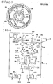
entire apparatus 10 may be seen by reference to Fig. 8. Preferably, the supply of cleansing liquids to drumsections first drum section 38 functions as a wash section for the metallic fines, whilesection 40 serves as a rinse section. Both the wash fluid and the rinse fluid are a heated alkaline water- base solution, with the alkaline detergent preferably being in an approximate concentration of 22g per liter (3 oz. per gallon). - The fines to be cleaned are supplied to drum
section 38 ofdrum 14 fromhopper 12 byconveyor 58.. The wash solution is applied to the fines, supplied to drumsection 38 as indicated schematically'at 80. The fines are transported throughdrum section 38 and deposited intodrum section 40, where the rinse solution is applied to the fines, supplied to drumsection 40 through a supply line indicated schematically at 82. The fines are then delivered from thedrum 14 at theupper end 16. - Following exposure to the fines within
drum section 38, the used wash solution is drained fromdrum 14 throughperforated wall section 52 intosump 68. The liquid is then removed fromsump 68 bypump 84, and passed through aheat exchange 86.Heat exchange 86 lowers the temperature of the wash solution, so that the subsequent separation of oil and dirt from the wash solution will be facilitated. Following cooling inheat exchange 86, the wash solution is directed toseparation tank 88. The wash solution is continuously passed throughseparation tank 88, wherein the oil is removed from the solution, collecting at the top of theseparation tank 88, while the dirt accumulates at the bottom. The cleaned solution is then passed to aheat tank 90, where the solution is heated to the cleaning temperature. The wash solution is then returned to thefirst section 38 ofdrum 14 bypump 92. - Similarly, following exposure to the fines within
drum section 40, the used rinse solution is drained throughperforated wall section 46 intosumps 78. The used solution is transported bypump 94 through aheat exchange 96 and passed through separa-'tion tank 98. Following separation of the oil and dirt from the rinse solution inseparator 98, the fluid is directed toheat tank 100 whereafter it is delivered bypump 102 back to drumsection 40. - The
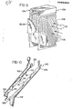
separator 104 contained within each ofseparation tanks Separator 104 includes aframe 106 to which is mounted a plurality ofcorrugated plates 108. Theplates 108 are mounted withinframe 106 so as to be mutually parallel, and are further mounted in an inclined orientation with the corrugations extending from the upper to the lower edge of eachplate 108. The fluid to be separated is directed intoseparator 104 as generally indicated byarrows 110, such that the fluid flows between theplates 108 in a direction perpendicular to the corrugations ofplates 108. - Referring now to Fig. 10, as the fluid.passes between a pair of
corrugated plates 108, theoil 112 contained within the solution moves toward the upper of the twoplates 108, indicated byarrows 14, due to its lower density relative to the water-based solution. Similarly, thedirt 116 carried within the solution precipitates downward toward the lower of theplates 108, as shown by arrows. Because both theoil 112 and thedirt 116 tend to collect into the corrugations of theplates 108, they are relatively shielded from the flow of solution continuously passing betweenplates 108. Thus, the oil l12 is able to move upwardly along each corrugation ofplates 108, as shown byarrows 120, until arriving the top ofseparation tank dirt 116 travels in a downward direction along the corrugations ofplates 108, as shown byarrows 122, until reaching the bottom ofseparation tank - Referring again to Fig. 8, the oil collected at the top of
separation tank 88 is drawn off as indicated at 124. Similarly, the oil from the top ofseparation tank 98 is drawn off as indicated at 126. The dirt collected at the bottom ofseparation tank 88 is removed therefrom by an auger (not shown) as indicated at 128, while the dirt collected at the bottom ofseparation tank 98 is similarly removed as indicated at 130. The dirt collected from bothtanks filter unit 132, where any remaining liquid is removed from the dirt. The dirt is then collected fromfilter unit 132 at 134, while the liquid is directed bypump 136 back intoseparation tank 88. - Because the concept embodied by the present invention of introducing metallic fines into a rotatable drum at a point remote from the lower end of the drum enables the
apparatus 10 to be used with relatively small particles such as metallic fines, it will be recognized that theapparatus 10 may also be modified for use in separating small particles such as fines from a slurry. Referring generally to Fig. 2, in such an application, a drum similar to drum 14 having only a single section is used. The slurry is provided as a stream into the uppermost end of the drum, so as to provide the maximum drum interior length for separation of the fines from the fluid in which they are suspended. As in the case of the apparatus for cleaning metallic fines, the fines separated from the fluid are recovered as they exit the upper end of the drum, while the fluid is drained away through a perforated wall section at the lower end of the drum. - While the methods herein described, and the form of apparatus for carrying these methods into effect, constitute preferred embodiments of this invention, it is to be understood that the invention is not lmited to these precise methods and form of apparatus, and that changes may be made in either without departing from the scope of the invention, which is defined in the appended claims.
Claims (12)
1. A continuous'method for cleaning metallic particles such as fines, chips and the like, characterized by the steps of:
continuously introducing the dirty metallic particles into a flow path in sufficient quantity to form a bed of the particles;
moving the bed of metallic particles along said flow path toward a discharge point while continuously agitating the bed of particles;
providing a gravity flow of a detergent solution along said flow path to flow through the bed of particles contra to their movement and draining the solution from the path at a point beyond the particle introduction point so as to carry dirt away from the bed.
2. A method for cleaning metallic particles such as fines, chips and the like, characterized by the steps of:
continuously introducing dirty particles into a rotating hollow drum (14) having a helical worm (42, 44) mounted to the interior thereof and extending from a first end of said drum (14) to a second end elevated with respect to said first end, the metallic particles being introduced into said drum at a point remote from said first end;
rotating the drum (14) such that the direction of advance of said worm (42, 44) is toward said second end;
introducing a detergent solution into said drum interior to flow over and through the particles;
draining said detergent solution from said drum interior near said first end of said drum; and
discharging the metallic particles from said second end of said drum.
3. A method for cleaning metallic particles such as fines, chips and the like, characterized by the steps of:
rotating a hollow drum (14) having mounted to the interior thereof a means (54) dividing said drum interior into a first section adjacent (38) a first end of said drum and a second section (40) adjacent a second end elevated with respect to said first end, said drum (14) further having mounted to the interior thereof a first helical worm (42) extending from said first end to said dividing means (54), and a second helical worm (44) extending from said dividing means to said second end, said drum (14) being rotated such that the direction of advance of said first and second worms (42, 44) is toward said second end;
continuously introducing the dirty metallic particles into said first section (38) of said drum interior at a point remote from said first end;
introducing a first solution into said first section (38) of said drum interior to flow over and through the particles therein;
draining said first solution near said first end of said drum (14);
discharging the metallic particles from said first section (38) at a point adjacent said dividing means (54), and introducing the particles into said second section (40) at a point remote from said first section (38);
introducing a second solution into said second section (40) to flow over and through the particles therein;
draining said second solution from said second section (40) near said dividing means (50); and
discharging the metallic particles from said second end of said drum (14).
4. A method as claimed in claims 1 or 2, including the further steps of:
directing said detergent solution following flow past said first point to a separation tank (88) adapted for separating oil and dirt carried by said detergent solution therefrom;
continuously flowing said detergent solution through said separation tank (88); and
returning said detergent solution to said drum interior.
5. An apparatus for cleaning metallic particles such as fines, chips and the like, including a rotatable hollow drum (14) having a first end and a second end, said drum being disposed with the lowest portion of said second end elevated with respect to the lowest portion of said first end; a helical worm (42, 44) mounted to the interior of said drum and extending from said first to said second end for transporting the metallic particles along said drum interior; and means (30) for rotating said drum (14) in a direction such that said worm (42, 44) advances the particles toward said second end characterized by:
means (58) for continuously introducing the metallic particles into the interior of said drum il4) at a point intermediate said first and said second ends;
means (60) for introducing a detergent solution into the interior of said drum (14) to flow over and through the particles; and
means (52) for draining said detergent solution near said first end of said drum.
6. An apparatus as claimed in claim 5, wherein said means (60) for introducing a detergent solution into the interior of said drum includes a conduit disposed within said drum interior along at least a portion of the length thereof and having at least one orifice therein located to discharge solution onto the particles.
7. An apparatus as claimed in claims 5 or 6, wherein said means (52) for draining said detergent solution from said drum (14) includes a portion of said drum (14) adjacent said first end thereof having a plurality of perforations defined therethrough.
8. An apparatus as claimed in claim 5, wherein said drum (14) is 'disposed such that the rotational axis of said drum (14) defines an angle (26) of less than 11° above horizontal.
9. An apparatus as claimed in claim 5, further comprising:
means (88) for continuously separating oil and dirt from said detergent solution;
means (68, 84) for collecting said detergent solution from said solution draining means (52) and directing said solution to said separating means (88); and
means (92) for directing said detergent solution from said separating means (88) to said solution introduction means (60).
10. An apparatus as claimed in claims 5 or 9 including means (90) for heating said detergent solution prior to introduction thereof into said drum (14),
11. An apparatus for cleaning metallic particles such as fines, chips and the like, including a rotatable hollow drum (14) having a first end and a second end, said drum (14) being disposed with the lowest portion of said second end slightly elevated with respect to the lowest portion of said first end characterized by:
a funnel member (54) having a relatively wide open end and a relatively narrow open end, said wide end being of substantially the same size and shape as the cross-section of said drum (14), said funnel member (54) being mounted to the interior of said drum (14) at said wide end of said funnel member (54) with said narrow end directed towards said second drum end, said funnel member defining a first section (38) of said drum (14) adjacent said first end and a second section (40) adjacent said second end;
a first helical worm (42) mounted to the interior of said drum (14) and said funnel member (54) and extending from said first end along said drum interior and said funnel member (54) to said narrow end;
a second helical worm (44) mounted to the interior of said drum (14) and extending from said funnel member (54) along said drum interior to said second end;
means (58) for continuously introducing the metallic particles into said first section (38) of said drum (14) at a point along said drum path remote from said first end;
means (30) for rotating said drum (14) in a direction such that said worm (42, 44) advances the particles toward said second end;
means (60) for introducing a first solution into said first drum section (38) to flow over and through the particles therein;
means (52) for draining said first solution from said first drum section (38);
means (70) for introducing a second solution into said second drum section (40) to flow over and through the particles therein; and
means (46) for draining said second solution from said second drum section (40).
12. An apparatus as claimed in claim 11, including means (56) for draining said first solution away from the metallic particles along said funnel member (54).
Applications Claiming Priority (2)
| Application Number | Priority Date | Filing Date | Title |
|---|---|---|---|
| US37347382A | 1982-04-30 | 1982-04-30 | |
| US373473 | 1982-04-30 |
Publications (2)
| Publication Number | Publication Date |
|---|---|
| EP0093264A2 true EP0093264A2 (en) | 1983-11-09 |
| EP0093264A3 EP0093264A3 (en) | 1984-07-11 |
Family
ID=23472571
Family Applications (1)
| Application Number | Title | Priority Date | Filing Date |
|---|---|---|---|
| EP83103031A Withdrawn EP0093264A3 (en) | 1982-04-30 | 1983-03-26 | Method and apparatus for cleaning metallic fines |
Country Status (2)
| Country | Link |
|---|---|
| EP (1) | EP0093264A3 (en) |
| JP (1) | JPS58204184A (en) |
Cited By (8)
| Publication number | Priority date | Publication date | Assignee | Title |
|---|---|---|---|---|
| WO1985003661A1 (en) * | 1984-02-20 | 1985-08-29 | Michel Thonney | Process for the treatment by bulk agitation of rough castings or machined parts and machine for implementing such process |
| EP0308382A1 (en) * | 1987-09-14 | 1989-03-22 | Lars Ake Hilmer Hakansson | Apparatus for treating small items |
| US5174315A (en) * | 1990-04-13 | 1992-12-29 | Durr Gmbh | System for cleaning objects |
| EP0557672A1 (en) * | 1992-02-24 | 1993-09-01 | Oddino Dorigo | Apparatus for the continuous treatment by means of liquids of small size materials fed in bulk |
| CN103386412A (en) * | 2013-07-09 | 2013-11-13 | 慈溪市共力磁业有限公司 | Cleaning and recycling technology of neodymium iron boron waste |
| CN108126956A (en) * | 2017-06-14 | 2018-06-08 | 南宁盛世凌云电子科技有限公司 | A kind of modified deduster equipment |
| CN114160480A (en) * | 2021-12-06 | 2022-03-11 | 鹤山市联发商品混凝土有限公司 | Sand-powder separation equipment for concrete and method thereof |
| CN117644058A (en) * | 2024-01-30 | 2024-03-05 | 安徽精诚食品科技有限公司 | A multilayer sieving mechanism for look selection machine |
Families Citing this family (1)
| Publication number | Priority date | Publication date | Assignee | Title |
|---|---|---|---|---|
| JPS63162084A (en) * | 1986-12-26 | 1988-07-05 | ジヤパン・フイ−ルド株式会社 | Washer |
Citations (2)
| Publication number | Priority date | Publication date | Assignee | Title |
|---|---|---|---|---|
| GB584744A (en) * | 1944-06-16 | 1947-01-22 | Curran Brothers Ltd | Improvements in or relating to apparatus for cleaning and otherwise treating small articles by spraying liquid thereon |
| US4073301A (en) * | 1975-09-26 | 1978-02-14 | Huntington Alloys, Inc. | Liquid treatment of small articles |
-
1983
- 1983-03-26 EP EP83103031A patent/EP0093264A3/en not_active Withdrawn
- 1983-04-30 JP JP7735483A patent/JPS58204184A/en active Pending
Patent Citations (2)
| Publication number | Priority date | Publication date | Assignee | Title |
|---|---|---|---|---|
| GB584744A (en) * | 1944-06-16 | 1947-01-22 | Curran Brothers Ltd | Improvements in or relating to apparatus for cleaning and otherwise treating small articles by spraying liquid thereon |
| US4073301A (en) * | 1975-09-26 | 1978-02-14 | Huntington Alloys, Inc. | Liquid treatment of small articles |
Cited By (11)
| Publication number | Priority date | Publication date | Assignee | Title |
|---|---|---|---|---|
| WO1985003661A1 (en) * | 1984-02-20 | 1985-08-29 | Michel Thonney | Process for the treatment by bulk agitation of rough castings or machined parts and machine for implementing such process |
| EP0308382A1 (en) * | 1987-09-14 | 1989-03-22 | Lars Ake Hilmer Hakansson | Apparatus for treating small items |
| US5174315A (en) * | 1990-04-13 | 1992-12-29 | Durr Gmbh | System for cleaning objects |
| EP0557672A1 (en) * | 1992-02-24 | 1993-09-01 | Oddino Dorigo | Apparatus for the continuous treatment by means of liquids of small size materials fed in bulk |
| CN103386412A (en) * | 2013-07-09 | 2013-11-13 | 慈溪市共力磁业有限公司 | Cleaning and recycling technology of neodymium iron boron waste |
| CN103386412B (en) * | 2013-07-09 | 2015-07-15 | 慈溪市共力磁业有限公司 | Cleaning and recycling technology of neodymium iron boron waste |
| CN108126956A (en) * | 2017-06-14 | 2018-06-08 | 南宁盛世凌云电子科技有限公司 | A kind of modified deduster equipment |
| CN114160480A (en) * | 2021-12-06 | 2022-03-11 | 鹤山市联发商品混凝土有限公司 | Sand-powder separation equipment for concrete and method thereof |
| CN114160480B (en) * | 2021-12-06 | 2022-07-12 | 鹤山市联发商品混凝土有限公司 | Sand-powder separation equipment for concrete and method thereof |
| CN117644058A (en) * | 2024-01-30 | 2024-03-05 | 安徽精诚食品科技有限公司 | A multilayer sieving mechanism for look selection machine |
| CN117644058B (en) * | 2024-01-30 | 2024-04-02 | 安徽精诚食品科技有限公司 | A multilayer sieving mechanism for look selection machine |
Also Published As
| Publication number | Publication date |
|---|---|
| JPS58204184A (en) | 1983-11-28 |
| EP0093264A3 (en) | 1984-07-11 |
Similar Documents
| Publication | Publication Date | Title |
|---|---|---|
| US6332983B1 (en) | Chip treatment device | |
| US4204855A (en) | Apparatus for dewatering granulated-slag slurry | |
| US4073301A (en) | Liquid treatment of small articles | |
| US4751006A (en) | Coolant reclamation unit | |
| US7638061B2 (en) | Coolant fluid cleaning method, system, and apparatus | |
| CA1305925E (en) | Filtering device for separating solids from liquids | |
| JPS60261516A (en) | Apparatus for removing lake substance and/or screen substance from liquid flowing through water channel | |
| US5341935A (en) | Method of separating resource materials from solid waste | |
| EP0093264A2 (en) | Method and apparatus for cleaning metallic fines | |
| JP4943309B2 (en) | Powder processing system and powder processing method | |
| CN210150836U (en) | Deslagging device of oil-containing waste water decomposition system | |
| KR20150074365A (en) | The industrial cleaner which removes pollutants from cleaning water by using waste heat | |
| RU2706271C2 (en) | Scale removal method from waste water | |
| US6976592B1 (en) | Liquid/solids waste separator | |
| US4453556A (en) | Spray treatment apparatus | |
| US4200530A (en) | Rotary filter | |
| SE430126C (en) | filtering device | |
| US4277339A (en) | Paint pigment skimmer | |
| EP0235654B1 (en) | Process and apparatus to purify contaminated sulphur | |
| US4256045A (en) | Apparatus and method for treating a gas with a liquid | |
| US3973573A (en) | Scrap washing system | |
| US4766916A (en) | Continuous conveyor degreasing and cleaning machine | |
| US3717255A (en) | Liquid clarification unit | |
| EP0563754A1 (en) | Purification device | |
| DE3734200A1 (en) | Process and device for removing adhering lubricant from workpieces |
Legal Events
| Date | Code | Title | Description |
|---|---|---|---|
| PUAI | Public reference made under article 153(3) epc to a published international application that has entered the european phase |
Free format text: ORIGINAL CODE: 0009012 |
|
| AK | Designated contracting states |
Designated state(s): DE FR GB |
|
| 17P | Request for examination filed |
Effective date: 19831103 |
|
| PUAL | Search report despatched |
Free format text: ORIGINAL CODE: 0009013 |
|
| AK | Designated contracting states |
Designated state(s): DE FR GB |
|
| STAA | Information on the status of an ep patent application or granted ep patent |
Free format text: STATUS: THE APPLICATION IS DEEMED TO BE WITHDRAWN |
|
| 18D | Application deemed to be withdrawn |
Effective date: 19850924 |
|
| RIN1 | Information on inventor provided before grant (corrected) |
Inventor name: CARMAN, LYLE Inventor name: WITTMAN, NELSON EUGENE |