EP0880193A1 - Antenna source for the transmission and reception of microwaves - Google Patents
Antenna source for the transmission and reception of microwaves Download PDFInfo
- Publication number
- EP0880193A1 EP0880193A1 EP98401216A EP98401216A EP0880193A1 EP 0880193 A1 EP0880193 A1 EP 0880193A1 EP 98401216 A EP98401216 A EP 98401216A EP 98401216 A EP98401216 A EP 98401216A EP 0880193 A1 EP0880193 A1 EP 0880193A1
- Authority
- EP
- European Patent Office
- Prior art keywords
- waveguide
- source according
- signals
- transducer
- reception
- Prior art date
- Legal status (The legal status is an assumption and is not a legal conclusion. Google has not performed a legal analysis and makes no representation as to the accuracy of the status listed.)
- Granted
Links
Images
Classifications
-
- H—ELECTRICITY
- H01—ELECTRIC ELEMENTS
- H01P—WAVEGUIDES; RESONATORS, LINES, OR OTHER DEVICES OF THE WAVEGUIDE TYPE
- H01P1/00—Auxiliary devices
- H01P1/20—Frequency-selective devices, e.g. filters
- H01P1/213—Frequency-selective devices, e.g. filters combining or separating two or more different frequencies
- H01P1/2131—Frequency-selective devices, e.g. filters combining or separating two or more different frequencies with combining or separating polarisations
-
- H—ELECTRICITY
- H01—ELECTRIC ELEMENTS
- H01P—WAVEGUIDES; RESONATORS, LINES, OR OTHER DEVICES OF THE WAVEGUIDE TYPE
- H01P1/00—Auxiliary devices
- H01P1/16—Auxiliary devices for mode selection, e.g. mode suppression or mode promotion; for mode conversion
- H01P1/161—Auxiliary devices for mode selection, e.g. mode suppression or mode promotion; for mode conversion sustaining two independent orthogonal modes, e.g. orthomode transducer
Definitions
- the invention relates to an antenna source for the emission and reception of polarized microwave waves.
- band C used today for certain satellite communications, from 3.625 to 4.2 GHz for reception and 5.85 to 6.425 GHz for transmission will be expanded down for reception (3.4 to 4.2 GHz) and down high (5.85 to 6.65 GHz) for transmission.
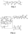
- FIG. 1 a source diagram antenna usable for transmitting and receiving signals in conventional C-band, i.e. with bandwidths of 575 MHz for transmission and reception.
- This antenna source known comprises a radiating element such as a horn 10 connected, via an adaptation section 12 and a guide of circular section waves 14, to a polarizer 16 intended for convert, on the one hand, the signals received into circular polarization into signals in linear polarization and, on the other hand, signals to be transmitted from linear polarization to polarization circular.
- the polarizer 16 is connected to a transducer 18 for separate the transmit and receive frequencies.
- This transducer comprises a waveguide of circular section whose surface exterior has longitudinal direction slots - that is to say whose largest dimension is parallel to the axis of the guide - connected to other waveguides (not shown) and filtering means (also not shown) eliminating the transmission frequencies and allowing reception frequencies to pass.
- the end of the waveguide of the transducer 18 which is opposite to that connected to polarizer 16 receives the signals to issue.
- the transmission channel includes filtering means for eliminate reception frequencies and, generally, means of orthogonal polarization.
- the invention overcomes these drawbacks.
- the antenna source according to the invention is characterized in that to transmit and receive wide signals bands, the transducer separating the emission and reception includes a square section waveguide or a guide of square or circular section (or another section) with ribs or corrugations perpendicular to the direction of propagation.
- this transducer is connected to the emission channel thanks to a section waveguide circular penetrating inside the waveguide of the transducer.
- This arrangement optimizes the separation between transmit and receive signals. This separation is further improved if there is provision at the end of the waveguide circular, inside the waveguide of the transducer, a iris, for example in the form of a double slit.
- the transducer has a waveguide of square section is advantageously provided, on each of its sides, a rectangular or slow opening, the long side is advantageously perpendicular to the axis of the waveguide.
- These slots allow extracting reception signals; they are associated with filtering means to eliminate the frequencies resignation.
- connection of the radiating element to the transducer separating the transmission and reception frequencies is such that it maintains the polarization state of the transmitted signals.
- the transmitted or received signals must undergo a conversion from their polarization state (circular to linear or linear in circular)
- a corresponding polarizer is provided in the transmission and / or reception channel, opposite to the radiating element with respect to the transducer. This provision also works well for large transmit and receive bands.
- slots of two opposite faces are, in one embodiment, connected to the Respective inputs of a "Magic tee" type adder.
- the signal received being circularly polarized the output of each of these adders provides the reception signal with a linear polarization of determined direction, the outputs of two magic tees being signals whose polarization vectors are perpendicular to each other.
- a coupler is advantageously used 3db / 90 °, in particular of the "Riblet" type.
- Such a coupler includes two rectangular section waveguides that connect in a junction area of parallelepiped shape, each waveguide comprising an incoming branch and an outgoing branch of the junction area. The latter has a height equal to the short side of the section of each waveguide and one width equal to twice the long side of said section.
- such a coupler is used in which the junction zone has, at least on a large wall, a elongated projection in the direction transverse to the spread.
- the corresponding projections in the junction area are either circular or elongated in the longitudinal direction.
- each of these ribs having, preferably a height which gradually decreases to inside each branch.
- a receiving duplexer For transmission, when it is necessary to issue right and / or left circularly polarized signals from linear polarized signals, a receiving duplexer is used the signals emitted in orthogonal linear polarizations and a polarizer which transforms linearly polarized signals into circularly polarized signals.
- a polarizer of the type "Septum" which combines the duplexer and polarizer functions has two waveguides of semicircular section receiving linearly polarized signals which converge on a circular section output waveguide.
- a wall or blade of longitudinal direction and decreasing in height in direction radial In the output waveguide, from the junction area input waveguides, a wall or blade of longitudinal direction and decreasing in height in direction radial. This wall extends along the axis of the waveguide of exit.
- the decrease in the height of the blade is either progressive, or, preferably, by jumps, that is to say in stairs. We found that we got the best results with such steps and that the number of these steps had an influence on the bandwidth of the polarizer. In general the more the number of steps increases the more the bandwidth of the polarizer is important.
- the embodiment of the invention that we are going to describe in relation to the figures concerns an antenna source broadband C transmission and reception.
- the frequencies are from 3.4 to 4.2 GHz and for transmission, the frequencies are 5.85 to 6.65 GHz.
- the reception frequency band extends on 800 MHz. The same is true for the frequency band resignation.
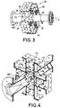
- the antenna source shown in Figure 2 includes a transducer 24 comprising a waveguide 26 of section square which, in the figure, is represented in cross section, that is to say perpendicular to the axis of propagation.
- a transducer 24 comprising a waveguide 26 of section square which, in the figure, is represented in cross section, that is to say perpendicular to the axis of propagation.
- Moon of the ends of this waveguide 26 is connected directly to a propagation horn (not shown).
- a propagation horn not shown.
- This connection can however include an element non-radiating other than a polarizer, by temple an extractor mode used to control a front antenna follow the trajectory of a satellite.
- the end 30 (FIG. 3) of the waveguide 26 which is opposite the end 28 connected to the horn is connected to a waveguide 32 of circular section receiving, via of a waveguide 34 of square section, the signals emission in right circular polarization and circular polarization left supplied by a polarizer 36.
- the purpose of the polarizer 36 is to transform the signals input with linear polarization into output signals with polarization circular.
- the input 38 of the polarizer 36 is connected to the output 40 of a duplexer 42 having two inputs, 44 and 46 respectively, receiving linearly polarized signals which must be transformed into polarized signals right circular and left circular polarization.
- Entrance 44 receives the signals which must be transformed into signals to right circular polarization and input 46 receives signals to be transformed into circularly polarized signals left.
- the duplexer 42 and polarizer 36 form a single element 50 constituting a polarizer of the "Septum" type, which will be described more far in relation to Figures 5 and 6.
- the lateral faces 52, 54, 56 and 58 of the waveguide 26 have rectangular openings, or slots, to which are connected reduced waveguides having the same rectangular section.
- the guides waves 60, 62, 64 and 66 have the position along the x axis of guide 26. It is important to note that the largest dimension slots, and therefore rectangular waveguides 60, 62, 64 and 66, is perpendicular to the x axis. In other words the rectangular openings extend transversely to to the direction of propagation.
- Waveguides 60, 62, 64 and 66 are equipped with filters, respectively 70, 72, 74 and 76 ( Figure 2), to remove transmit frequencies and pass frequencies reception.
- the rectangular waveguides associated with the faces opposite 52 and 56 of the guide 26 are connected to the two inputs, 78 and 80 respectively, of a "magic tee" 82 (figure 2) whose output is connected to the first input 84 of a coupler 86 of the 3db / 90 ° type.
- the rectangular waveguides associated with the opposite sides 54 and 58 are connected to the respective inputs of a second "magic tee" 90 whose output is connected to the second input 92 of coupler 86.
- the coupler 86 receives, On its first input 84, a signal of a linear polarization of a first direction and, on its second input 92, a signal of linear polarization orthogonal. These signals are the two components of the wave at right and left circular polarization in the source. He gives on its outputs, respectively 94 and 96, signals which represent and differentiate the two circular polarizations orthogonal. For example, on output 94 the signal represents right circular polarization and on output 96 the signal represents the left circular polarization. An example of such coupler will be described later in relation to FIGS. 7 to 9.
- the square section of the waveguide 26 also contributes to expand the transmit and receive bands.
- the waveguide 26 has, on its internal face, corrugations, that is to say, ribs extending perpendicular to the x axis.
- the transducer 24 comprises, in place of the guide 26 of square section, a waveguide of circular section also with corrugations to broaden the band with respect to a waveguide devoid of such corrugations.
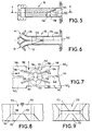
- the waveguide 26 is connected by its front face 28 to a waveguide 100 (FIG. 4) ensuring the transition between the 26 square section waveguide and the section waveguide circular cone.
- the waveguide 32 of circular section for the connection to the transmission channel ends, inside the guide of waves 26, by an iris 102 which, in the example, has the shape of a cross, that is to say of two perpendicular slots 104 and 106.
- the iris 102 short-circuits the reception frequencies.
- This ring 108 in combination with the iris 102, aims to reflect the signals of reception towards the slots of the lateral walls of the guide 26 and, thus, preventing reception signals from entering the emission channel.
- the circular waveguide 32 of the emission channel has other iris 110, 112 in the form of rings having a role impedance matching for the transmission frequencies included between 5.85 and 6.65 GHz.
- irises 114, 116 and 118 are also provided in each reduced rectangular section guide of the reception channel, for example in the waveguide 60 (FIG. 4).
- the irises 116 and 118 are each formed from of two rectangular plates or ribs projecting from the internal faces of the short sides of the waveguide 60. These ribs, which are referenced, respectively 116 1 and 116 2 for the iris 116, are perpendicular to the large faces 117 of the guide 60.
- iris 114 the closest to the corresponding slot (not visible in Figure 4) of the waveguide 26, is formed from two plates 114 1 and 114 2 also perpendicular to the small faces of the guide waves 60, but parallel to the large faces 117.
- Iris 114, 116 and 118 constitute the filtering means allowing to reject the frequencies of emission and pass reception frequencies.
- Figures 5 and 6 represent a Septum polarizer in the emission channel of the antenna shown in Figure 2.
- Septum type polarizer 50 has two guides of input waves 130 and 132. Input 44 is at the end waveguide 130 and inlet 46 is at the end of the guide of waves 132 ( Figures 2 and 6). In the vicinity of the entrances the guides are of rectangular section and are then of semi-circular section.
- These two waveguides 130 and 132 are connected continuously to a waveguide 134 of circular section, of which the diameter is equal to the diameter of the section of each of the semicircular guides 130 and 132.
- a central wall or blade 136 is provided, the plane of which contains the axis of the waveguide 134.
- its height, in the radial direction is equal to the internal diameter of guide 134.
- the width of this wall 136 decreases by saints, that is to say that its end section has steps. In the example, four steps are planned, respectively 140, 142, 144 and 146.
- the quality of the polarization circular i.e. the ellipticity rate, depends on the cutting of the end 138, in particular of the number of steps and length (in axial direction) and height (in radial direction) of each of these steps. In particular, we found that the higher the number of steps, the more bandwidth of the polarizer is wide. We will also note that the lengths and heights of the steps are uneven.
- FIGS 7 to 9 represent an embodiment of the coupler 86 in the path of reception.
- a 3db / 90 ° coupler of the type "Riblet" (figure 2), is such that a signal applied to an input 84 is transmitted according to two signals of equal amplitudes on the outputs 94 and 96, these output signals having a phase shift 90 ° to each other.
- a signal applied on the second input 92 is transmitted with equal amplitudes on outputs 94 and 96 and with a 90 ° phase shift between these output signals.
- Such a coupler comprises two waveguides 160 and 162 which are connected according to a junction zone 164.
- These guides waves have a rectangular section and are arranged so such as their small faces 166 and 168, corresponding to the short sides of the section, are adjacent and only in the area junction 164 these faces or walls are removed.
- the junction zone has a floor wall 170 and a ceiling wall 172 (FIG. 8).
- the width of these walls - i.e. their dimension perpendicular to the propagation y and parallel to the large faces of the guides 160 and 162 - is equal to twice the largest dimension of the rectangular section of each waveguide 160, 162.
- the height of the junction area i.e. the distance between the walls 170 and 172, is equal to the short side of the section of guides 160 and 162.
- the floor wall 170 has a projection 174 of which base 176 has a curvilinear shape elongated transversely to the direction Y of propagation (figure 7).
- This base 176 of the projection 174 occupies a large part, of the order of 75% of the floor area 170.
- the top 178 of this projection 174 is of substantially smaller dimensions than those of base 176. This top is also elongated transversely to the Y direction of propagation.
- the base and the top of the projection are centered relative to the junction zone 164.
- the projection 174 is extended by ribs, respectively 180, 182, 184 and 186.
- ribs respectively 180, 182, 184 and 186.
- the rib 180 is constituted by a wall perpendicular to the floor 170. Inside the junction zone 164 the height of this rib 180 is the same as the height of the projection 174. This rib 180 is directed towards the branch of input 160 1 of the waveguide 160 and it partially penetrates this branch 160 1 . In this branch its height gradually decreases. In other words, the end of the rib 180 has the shape of a wedge or bevel 190. Opposite the bevel 190, the rib 180 is connected to the end 192, facing the waveguide 160, from the top 178 of the projection 174.
- the rib 184 is directed towards the outlet branch 160 2 of the waveguide 160.
- the rib 182 is directed towards the inlet branch 162 1 of the waveguide 162 and the rib 186 is directed towards the outlet branch 162 2 of this same waveguide 162.
- the ribs 182 and 186 are connected to the end 194 of the apex 178 of the projection which is opposite to the end 192 to which the two other ribs 180 and 184 are connected.
- An adjustment screw 196 is provided in the ceiling 172 near its edge 198.
- Another adjustment screw 200 is located in the center of the ceiling 172. These screws allow adjustment of the coupling between the outgoing waves, i.e. an adjustment of the relative amplitudes of the waves.
- the projection 174 elongated transversely at direction Y of signal propagation allowed to keep the equal properties of the amplitudes of the output to within 0.1 dB over a wide frequency band and, in in all cases, on the 800 MHz of the receiving C band.
- the ribs 180, 182, 184 and 186 further significantly improve the quality of the coupler on the desired bandwidth.
- the dimensions of the zone 164 are of the same order of magnitude as the dimensions of the corresponding zone of a conventional Riblet coupler. In a manner known per se, the properties of the coupler result from the fact that the modes TE 10 and TE 20 coexist in the junction zone 164.
- the TE 10 mode is transformed into a TE 10 U-shaped mode, which gives it a more stationary guided wavelength ⁇ G and a greater bandwidth of use in relation to the dimensions of the U.
- the ceiling 172 of the junction zone 164 has a projection 210 analogous to projection 174 and which is also extended by four ribs similar to the corresponding associated ribs to the projection 174.
- the dimensions and arrangement of the projection 210 and associated ribs are the same as those of the projection 174 and its corresponding ribs.
- the projection 174 and, optionally, the projection 210 is not constituted by a continuous element but by a set of projections such as nipples sufficiently close together to give the same result as a continuous projection.
- the emission one can also foresee the use a duplexer and a polarizer turned 90 °, the emission taking place with linear polarization signals orthogonal.
- the source has a number of accesses lower than the four accesses provided in the examples described above (two transmitting accesses and two receiving accesses). In in this case, the unused accesses will be loaded.
- the antenna source described applies in particular telecommunications antennas with a diameter between 1 and 32 meters or more.
Abstract
Description
L'invention est relative à une source d'antenne pour l'émission et la réception d'ondes hyperfréquences polarisées.The invention relates to an antenna source for the emission and reception of polarized microwave waves.
On sait que pour transmettre de grandes quantités d'informations à l'aide de signaux radioélectriques, on a intérêt à utiliser des signaux polarisés et dont les fréquences porteuses ont des valeurs élevées et des bandes larges.We know that to transmit large quantities of information using radio signals, we are interested to use polarized signals and whose carrier frequencies have high values and wide bands.
Par ailleurs, quand une même antenne est destinée à émettre et recevoir des signaux, il est nécessaire que les bandes de fréquences d'émission soient distinctes des bandes de fréquences de réception.Furthermore, when the same antenna is intended to transmit and receive signals, it is necessary that the bands of emission frequencies are distinct from the frequency bands reception.
L'augmentation constante du trafic de télécommunications amène à élargir les bandes des fréquences d'émission et de réception. Par exemple, la bande C, utilisée aujourd'hui pour certaines communications par satellites, de 3,625 à 4,2 GHz pour la réception et de 5,85 à 6,425 GHz pour l'émission va être élargie vers le bas pour la réception (3,4 à 4,2 GHz ) et vers le haut (5,85 à 6,65 GHz) pour l'émission.The constant increase in telecommunications traffic leads to widening the frequency bands of emission and reception. For example, band C, used today for certain satellite communications, from 3.625 to 4.2 GHz for reception and 5.85 to 6.425 GHz for transmission will be expanded down for reception (3.4 to 4.2 GHz) and down high (5.85 to 6.65 GHz) for transmission.
On a représenté sur la figure 1, un schéma de source
d'antenne utilisable pour l'émission et la réception de signaux
en bande C classique, c'est-à-dire avec des largeurs de bandes de
575 MHz pour l'émission et la réception. Cette source d'antenne
connue comporte un élément rayonnant tel qu'un cornet 10 relié,
par l'intermédiaire d'une section d'adaptation 12 et d'un guide
d'ondes de section circulaire 14, à un polariseur 16 destiné à
convertir, d'une part, les signaux reçus en polarisation circulaire
en des signaux en polarisation linéaire et, d'autre part,
les signaux à émettre d'une polarisation linéaire en une polarisation
circulaire.There is shown in Figure 1, a source diagram
antenna usable for transmitting and receiving signals
in conventional C-band, i.e. with bandwidths of
575 MHz for transmission and reception. This antenna source
known comprises a radiating element such as a
Le polariseur 16 est relié à un transducteur 18 pour
séparer les fréquences d'émission et de réception. Ce transducteur
comporte un guide d'ondes de section circulaire dont la surface
extérieure présente des fentes de direction longitudinale -
c'est-à-dire dont la plus grande dimension est parallèle à l'axe
du guide - connectées à d'autres guides d'ondes (non montrés) et
à des moyens de filtrage (également non montrés) éliminant les
fréquences d'émission et laissant passer les fréquences de réception.The
L'extrémité du guide d'ondes du transducteur 18 qui est
opposée à celle connectée au polariseur 16 reçoit les signaux à
émettre. La voie d'émission comporte des moyens de filtrage pour
éliminer les fréquences de réception et, généralement, des moyens
de polarisation orthogonaux.The end of the waveguide of the
On a constaté qu'une source d'antenne de ce type ne donnait pas de résultats satisfaisants pour l'émission et la réception des signaux à large bande, notamment pour la bande C élargie mentionnée ci-dessus.It has been found that an antenna source of this type does not not give satisfactory results for transmission and reception of broadband signals, especially for C-band enlarged mentioned above.
L'invention permet de remédier à ces inconvénients.The invention overcomes these drawbacks.
La source d'antenne conforme à l'invention est caractérisée en ce que, pour émettre et recevoir des signaux à larges bandes, le transducteur séparant les signaux d'émission et de réception comporte un guide d'ondes de section carrée ou un guide d'ondes de section carrée ou circulaire (ou d'une autre section) présentant des nervures ou corrugations perpendiculaires à la direction de propagation.The antenna source according to the invention is characterized in that to transmit and receive wide signals bands, the transducer separating the emission and reception includes a square section waveguide or a guide of square or circular section (or another section) with ribs or corrugations perpendicular to the direction of propagation.
Dans le mode de réalisation préféré, ce transducteur est relié à la voie d'émission grâce à un guide d'ondes de section circulaire pénétrant à l'intérieur du guide d'ondes du transducteur. Cette disposition permet d'optimiser la séparation entre les signaux d'émission et de réception. Cette séparation est encore améliorée si on prévoit à l'extrémité du guide d'ondes circulaire, à l'intérieur du guide d'ondes du transducteur, un iris, par exemple en forme d'une double fente.In the preferred embodiment, this transducer is connected to the emission channel thanks to a section waveguide circular penetrating inside the waveguide of the transducer. This arrangement optimizes the separation between transmit and receive signals. This separation is further improved if there is provision at the end of the waveguide circular, inside the waveguide of the transducer, a iris, for example in the form of a double slit.
Lorsque le transducteur comporte un guide d'ondes de section carrée on prévoit avantageusement, sur chacune de ses faces, une ouverture rectangulaire, ou lente, dont le grand côté est avantageusement perpendiculaire à l'axe du guide d'ondes. Ces fentes permettent d'extraire les signal de réception ; elles sont associées à des moyens de filtrage pour éliminer les fréquences d'émission.When the transducer has a waveguide of square section is advantageously provided, on each of its sides, a rectangular or slow opening, the long side is advantageously perpendicular to the axis of the waveguide. These slots allow extracting reception signals; they are associated with filtering means to eliminate the frequencies resignation.
Dans un mode de réalisation préféré de l'invention, la connexion de l'élément rayonnant au transducteur séparant les fréquences d'émission et de réception est telle c'elle maintient l'état de polarisation des signaux transmis.In a preferred embodiment of the invention, the connection of the radiating element to the transducer separating the transmission and reception frequencies is such that it maintains the polarization state of the transmitted signals.
Si, dans ce cas, les signaux transmis ou reçus doivent subir une conversion de leur état de polarisation (circulaire en linéaire ou linéaire en circulaire), un polariseur correspondant est prévu dans la voie d'émission et/de réception, à l'opposé de l'élément rayonnant par rapport au transducteur. Cette disposition est également favorable au fonctionnent pour des larges bandes d'émission et de réception.If, in this case, the transmitted or received signals must undergo a conversion from their polarization state (circular to linear or linear in circular), a corresponding polarizer is provided in the transmission and / or reception channel, opposite to the radiating element with respect to the transducer. This provision also works well for large transmit and receive bands.
Lorsqu'on prévoit des fentes permettant d'extraire les signaux de réception du guide d'ondes du transducteur, les fentes de deux faces opposées sont, dans une réalisation, reliées aux entrées respectives d'un additionneur du type "Té magique". Le signal reçu étant à polarisation circulaire la sortie de chacun de ces additionneurs fournit le signal de réception avec une polarisation linéaire de direction déterminée, les sorties des deux Tés magiques étant des signaux dont les vecteurs de polarisation sont perpendiculaires entre eux.When slots are provided to extract the transducer waveguide reception signals, slots of two opposite faces are, in one embodiment, connected to the Respective inputs of a "Magic tee" type adder. The signal received being circularly polarized the output of each of these adders provides the reception signal with a linear polarization of determined direction, the outputs of two magic tees being signals whose polarization vectors are perpendicular to each other.
Pour transformer ces signaux de polarisations linéaires orthogonales caractérisant les polarisations circulaires droite et gauche dans la source, on utilise avantageusement un coupleur 3db/90°, notamment de type "Riblet". Un tel coupleur comprend deux guides d'ondes de section rectangulaire qui se raccordent dans une zone de jonction de forme parallèlipipèdique, chaque guide d'ondes comprenant une branche entrant et une branche sortant de la zone de jonction. Cette dernière présente une hauteur égale au petit côté de la section de chaque guide d'ondes et une largeur égale au double du grand côté de ladite section. Pour équilibrer les amplitudes des signaux des branches de sortie, on prévoit généralement au moins une saillie d'une grande paroi à l'intérieur de la zone de jonction.To transform these linear polarization signals orthogonal characterizing the right circular polarizations and left in the source, a coupler is advantageously used 3db / 90 °, in particular of the "Riblet" type. Such a coupler includes two rectangular section waveguides that connect in a junction area of parallelepiped shape, each waveguide comprising an incoming branch and an outgoing branch of the junction area. The latter has a height equal to the short side of the section of each waveguide and one width equal to twice the long side of said section. For balance the amplitudes of the signals of the output branches, we generally provides at least one projection of a large wall to inside the junction area.
Pour optimiser la séparation de polarisation effectuée par le coupleur, c'est-à-dire pour obtenir, sur une large bande de fréquences, des signaux déphasés de 90° ayant des amplitudes égales, par exemple à environ 0,1 db près, selon une autre disposition de l'invention, on utilise un tel coupleur dans lequel la zone de jonction présente, au moins sur une grande paroi, une saillie de forme allongée dans la direction transversale à la propagation.To optimize the polarization separation performed by the coupler, that is to say to obtain, over a wide band frequency, 90 ° phase shifted signals with amplitudes equal, for example to about 0.1 db, according to another arrangement of the invention, such a coupler is used in which the junction zone has, at least on a large wall, a elongated projection in the direction transverse to the spread.
Dans les coupleurs "Riblet" connus les saillies correspondantes dans la zone de jonction sont soit circulaires, soit allongées en direction longitudinale.In known "Riblet" couplers, the corresponding projections in the junction area are either circular or elongated in the longitudinal direction.
Avec une saillie allongée en direction transversale, on obtient des résultats sensiblement meilleurs qu'avec les coupleurs connus, c'est-à-dire que les signaux de sortie sont équilibrés en amplitude sur une plus large bande de fréquences.With an elongated projection in transverse direction, achieves significantly better results than with couplers known, i.e. the output signals are balanced in amplitude over a wider frequency band.
Des résultats encore supérieurs sont obtenus quand la saillie est prolongée selon des nervures dirigées vers chacune des branches des guides d'ondes, chacune de ces nervures présentant, de préférence, une hauteur qui diminue progressivement à l'intérieur de chaque branche.Even better results are obtained when the projection is extended according to ribs directed towards each branches of the waveguides, each of these ribs having, preferably a height which gradually decreases to inside each branch.
Pour l'émission, quand il est nécessaire d'émettre des signaux à polarisation circulaire droite et/ou gauche à partir de signaux à polarisation linéaire, on utilise un duplexeur recevant les signaux émis en polarisations linéaires orthogonales et un polariseur qui transforme les signaux polarisés linéairement en des signaux polarisés circulairement.For transmission, when it is necessary to issue right and / or left circularly polarized signals from linear polarized signals, a receiving duplexer is used the signals emitted in orthogonal linear polarizations and a polarizer which transforms linearly polarized signals into circularly polarized signals.
On peut également utiliser un polariseur de type "Septum" qui combine les fonctions duplexeur et polariseur. Un tel polariseur comporte deux guides d'ondes de section semicirculaire recevant des signaux à polarisations linéaires qui convergent vers un guide d'ondes de sortie de section circulaire. Dans le guide d'ondes de sortie, à partir de la zone de jonction des guides d'ondes d'entrée, on prévoit une paroi ou lame de direction longitudinale et de hauteur décroissante en direction radiale. Cette paroi s'étend selon l'axe du guide d'ondes de sortie. La décroissance de la hauteur de la lame est soit progressive, soit, préférentiellement, par sauts, c'est-à-dire en marches d'escalier. On a constaté qu'on obtenait les meilleurs résultats avec de telles marches et que le nombre de ces marches avait une influence sur la bande passante du polariseur. En général plus le nombre de marches augmente plus la bande passante du polariseur est importante.It is also possible to use a polarizer of the type "Septum" which combines the duplexer and polarizer functions. A such a polarizer has two waveguides of semicircular section receiving linearly polarized signals which converge on a circular section output waveguide. In the output waveguide, from the junction area input waveguides, a wall or blade of longitudinal direction and decreasing in height in direction radial. This wall extends along the axis of the waveguide of exit. The decrease in the height of the blade is either progressive, or, preferably, by jumps, that is to say in stairs. We found that we got the best results with such steps and that the number of these steps had an influence on the bandwidth of the polarizer. In general the more the number of steps increases the more the bandwidth of the polarizer is important.
D'autres caractéristiques et avantages de l'invention
apparaítront avec la description de certains de ses modes de
réalisation, celle-ci étant effectuée en se référant aux dessins
ci-annexés sur lesquels :
L'exemple de réalisation de l'invention que l'on va décrire en relation avec les figures concerne une source d'antenne d'émission et de réception en bande C élargie. Come indiqué ci-dessus, pour la réception les fréquences sont de 3,4 à 4,2 GHz et pour l'émission, les fréquences sont de 5,85 à 6,65 GHz. En d'autres termes, la bande de fréquences de réception s'étend sur 800 MHz. Il en est de même pour la bande de fréquences d'émission.The embodiment of the invention that we are going to describe in relation to the figures concerns an antenna source broadband C transmission and reception. Come indicated above, for reception the frequencies are from 3.4 to 4.2 GHz and for transmission, the frequencies are 5.85 to 6.65 GHz. In other words, the reception frequency band extends on 800 MHz. The same is true for the frequency band resignation.
La source d'antenne représentée sur la figure 2 comporte
un transducteur 24 comprenant un guide d'ondes 26 de section
carrée qui, sur la figure, est représenté en section transversale,
c'est-à-dire perpendiculaire à l'axe de propagation. L'une
des extrémités de ce guide d'ondes 26 est connectée directement à
un cornet de propagation (non représenté). Par "directement" on
entend que le transducteur 24 n'est pas relié au cornet de propagation,
ou à un autre organe rayonnant, par l'intermédiaire
d'un polariseur. Cette connexion peut cependant comporter un élément
non rayonnant autre qu'un polariseur, par temple un extracteur
de mode servant à l'asservissement d'une antenne devant
suivre la trajectoire d'un satellite.The antenna source shown in Figure 2 includes
a
L'extrémité 30 (figure 3) du guide d'ondes 26 qui est
opposée à l'extrémité 28 reliée au cornet est connectée à un
guide d'ondes 32 de section circulaire recevant, par l'intermédiaire
d'un guide d'ondes 34 de section carrée, les signaux
d'émission en polarisation circulaire droite et polarisation circulaire
gauche fournis par un polariseur 36.The end 30 (FIG. 3) of the
Le polariseur 36 a pour but de transformer les signaux
d'entrée à polarisation linéaire en des signaux de sortie à polarisation
circulaire. Ainsi l'entrée 38 du polariseur 36 est
reliée à la sortie 40 d'un duplexeur 42 présentant deux entrées,
respectivement 44 et 46, recevant des signaux polarisés linéairement
qui doivent être transformés en des signal à polarisation
circulaire droite et polarisation circulaire gauche. L'entrée 44
reçoit les signaux qui doivent être transformés en des signaux à
polarisation circulaire droite et l'entrée 46 reçoit les signaux
devant être transformés en des signaux à polarisation circulaire
gauche.The purpose of the
Dans le mode de réalisation préféré de l'invention, le
duplexeur 42 et le polariseur 36 forment un élément unique 50
constituant un polariseur de type "Septum", qui sera décrit plus
loin en relation avec les figures 5 et 6.In the preferred embodiment of the invention, the
Les faces latérales 52, 54, 56 et 58 du guide d'ondes
26 présentent des ouvertures rectangulaires, ou fentes, auxquelles
sont connectés des guides d'ondes réduits ayant la même
section rectangulaire. On voit sur la figure 3 que la face 52 est
prolongée par le guide d'ondes rectangulaire 60. Les guides
d'ondes 60, 62, 64 et 66 ont la être position le long de l'axe x
du guide 26. Il est important de noter que la plus grande dimension
des fentes, et donc des guides d'ondes rectangulaires 60,
62, 64 et 66, est perpendiculaire à l'axe x. Autrement dit les
ouvertures rectangulaires s'étendent transversalement par rapport
à la direction de propagation.The lateral faces 52, 54, 56 and 58 of the
Les guides d'ondes 60, 62, 64 et 66 sont équipés de
filtres, respectivement 70, 72, 74 et 76 (figure 2), pour éliminer
les fréquences d'émission et laisser passer les fréquences
de réception.
Les guides d'ondes rectangulaires associés aux faces
opposées 52 et 56 du guide 26 sont reliés aux deux entrées,
respectivement 78 et 80, d'un "Té magique" 82 (figure 2) dont la
sortie est reliée à la première entrée 84 d'un coupleur 86 du
type 3db/90°.The rectangular waveguides associated with the faces
opposite 52 and 56 of the
De même, les guides d'ondes rectangulaires associés aux
faces opposées 54 et 58 sont reliés aux entrées respectives d'un
second "Té magique" 90 dont la sortie est connectée à la seconde
entrée 92 du coupleur 86.Similarly, the rectangular waveguides associated with the
Le coupleur 86 reçoit, Sur sa première entrée 84, un
signal d'une polarisation linéaire d'une première direction et,
sur sa seconde entrée 92, un signal d'une polarisation linéaire
orthogonale. Ces signaux sont les deux composantes de l'onde à
polarisation circulaire droite et gauche dans la source. Il fournit
sur ses sorties, respectivement 94 et 96, des signaux qui
représentent et différentient les deux polarisations circulaires
orthogonales. Par exemple, sur la sortie 94 le signal représente
la polarisation circulaire droite et sur la sortie 96 le signal
représente la polarisation circulaire gauche. Un exemple d'un tel
coupleur sera décrit plus loin en relation avec les figures 7 à
9.The
On notera ici que le fait de prévoir des polariseurs séparés pour l'émission et la réception permet d'optimiser ces derniers et de réaliser une source d'antenne pour recevoir et émettre des signaux en bande C élargie.It will be noted here that the fact of providing polarizers separate for transmission and reception optimizes these last and realize an antenna source to receive and transmit signals in wide C band.
La section carrée du guide d'ondes 26 contribue aussi à
élargir les bandes d'émission et de réception.The square section of the
En variante (non représentée) le guide d'ondes 26 présente,
sur sa face interne, des corrugations, c'est-à-dire des
nervures s'étendant perpendiculairement à l'axe x. Dans une autre
variante, le transducteur 24 comporte, à la place du guide
d'ondes 26 de section carrée, un guide d'ondes de section circulaire
également doté de corrugations permettant d'élargir la
bande par rapport à un guide d'ondes dépourvu de telles corrugations.As a variant (not shown) the
On se réfère maintenant aux figures 3 et 4.We now refer to Figures 3 and 4.
Le guide d'ondes 26 est relié par sa face avant 28 à un
guide d'ondes 100 (figure 4) assurant la transition entre le
guide d'ondes 26 de section carrée et le guide d'ondes de section
circulaire du cornet.The
Le guide d'ondes 32 de section circulaire pour la
connexion à la voie d'émission se termine, à l'intérieur du guide
d'ondes 26, par un iris 102 qui, dans l'exemple, a la forme d'une
croix, c'est-à-dire de deux fentes perpendiculaires 104 et 106.
L'iris 102 court-circuite les fréquences de réception.The
A l'arrière de cet iris 106, contre la face interne de
la paroi 30, on prévoit un anneau 108. Cet anneau 108, en combinaison
avec l'iris 102, a pour but de réfléchir les signaux de
réception vers les fentes des parois latérales du guide 26 et,
ainsi, empêcher que les signaux de réception ne pénètrent dans la
voie d'émission.Behind this
Le guide d'ondes circulaire 32 de la voie d'émission
comporte d'autres iris 110, 112 en forme d'anneaux ayant un rôle
d'adaptation d'impédance pour les fréquences d'émission comprises
entre 5,85 et 6,65 GHz.The
Dans chaque guide réduit de section rectangulaire de la
voie de réception, par exemple dans le guide d'ondes 60 (figure
4), on prévoit aussi des iris 114, 116 et 118. Les iris 116 et
118 sont formes, chacun, à partir de deux plaques ou nervures
rectangulaires en saillie des faces internes des petits côtés du
guide d'ondes 60. Ces nervures, qui sont référencées, respectivement
1161 et 1162 pour l'iris 116, sont perpendiculaires aux
grandes faces 117 du guide 60.In each reduced rectangular section guide of the reception channel, for example in the waveguide 60 (FIG. 4), irises 114, 116 and 118 are also provided. The
Par contre l'iris 114, le plus proche de la fente correspondante
(non visible sur la figure 4) du guide d'ondes 26,
est forme à partir de deux plaques 1141 et 1142 également perpendiculaires
aux petites faces du guide d'ondes 60, mais parallèles
aux grandes faces 117.By cons iris 114, the closest to the corresponding slot (not visible in Figure 4) of the
Les iris 114, 116 et 118 constituent les moyens de filtrage
permettant de rejeter les fréquences d'émission et de
laisser passer les fréquences de réception.
On se réfère maintenant aux figures 5 et 6 qui représentent un polariseur Septum se trouvant dans la voie d'émission de l'antenne représentée sur la figure 2.We now refer to Figures 5 and 6 which represent a Septum polarizer in the emission channel of the antenna shown in Figure 2.
Le polariseur 50 de type Septum comporte deux guides
d'ondes d'entrée 130 et 132. L'entrée 44 se trouve à l'extrémité
du guide d'ondes 130 et l'entrée 46 est à l'extrémité du guide
d'ondes 132 (figures 2 et 6). Au voisinage des entrées les guides
sont de section rectangulaire et sont ensuite de section semi-circulaire.
Ces deux guides d'ondes 130 et 132 se raccordent de
façon continue à un guide d'ondes 134 de section circulaire, dont
le diamètre est égal au diamètre de la section de chacun des
guides semi-circulaires 130 et 132. Dans le guide d'ondes 134, à
partir de la zone de raccordement entre les guides d'ondes 130 et
132, on prévoit une paroi, ou lame, centrale 136 dont le plan
contient l'axe du guide d'ondes 134. Dans la zone de raccordement
entre les guides 130 et 132 sa hauteur, en direction radiale, est
égale au diamètre interne du guide 134. Vers la zone de sortie
138 la largeur de cette paroi 136 diminue par saints, c'est-à-dire
que sa section d'extrémité présente des marches. Dans l'exemple,
on prévoit quatre marches, respectivement 140, 142, 144 et 146.These two
Sur les entrées 44 et 46 on applique des signaux à
polarisation linéaire qui sont transformés, à la sortie 150, en
des signaux à polarisation circulaire. Les signaux appliqués sur
l'entrée 44 sont transformés en signaux à polarisation circulaire
droite et les signaux appliqués sur l'entrée 46 sont transformés
en des signaux à polarisation circulaire gauche.On
Dans la bande C élargie la qualité de la polarisation
circulaire, c'est-à-dire le taux d'ellipticité, dépend de la
découpe de l'extrémité 138, en particulier du nombre de marches
et de la longueur (en direction axiale) et de la hauteur (en
direction radiale) de chacune de ces marches. En particulier, on
a constaté que plus le nombre de marches est élevé et plus la
bande passante du polariseur est large. On remarquera aussi que
les longueurs et les hauteurs des marches sont inégales.In the extended C band the quality of the polarization
circular, i.e. the ellipticity rate, depends on the
cutting of the
On se réfère maintenant aux figures 7 à 9 qui représentent
un mode de réalisation du coupleur 86 dans la voie de
réception. De façon en soi connue, un coupleur 3db/90° de type
"Riblet" (figure 2), est tel qu'un signal appliqué sur une entrée
84 est transmis selon deux signaux d'amplitudes égales sur les
sorties 94 et 96, ces signaux de sorties présentant un déphasage
de 90° l'un par rapport à l'autre. De même, un signal appliqué
sur la seconde entrée 92 est transmis avec des amplitudes égales
sur les sorties 94 et 96 et avec un déphasage de 90° entre ces
signaux de sortie.We now refer to Figures 7 to 9 which represent
an embodiment of the
Un tel coupleur comporte deux guides d'ondes 160 et 162
qui se raccordent selon une zone 164 de jonction. Ces guides
d'ondes ont une section rectangulaire et sont disposés de façon
telle que leurs petites faces 166 et 168, correspondant aux
petits côtés de la section, soient adjacentes et que dans la zone
de jonction 164 ces faces ou parois soient supprimées.Such a coupler comprises two
La zone de jonction présente une paroi de plancher 170
et une paroi de plafond 172 (figure 8). La largeur de ces
parois - c'est-à-dire leur dimension perpendiculairement à la
propagation y et parallèlement aux grandes faces des guides 160
et 162 - est égale au double de la plus grande dimension de la
section rectangulaire de chaque guide d'ondes 160, 162. La hauteur
de la zone de jonction, c'est-à-dire la distance entre les
parois 170 et 172, est égale au petit côté de la section des
guides 160 et 162.The junction zone has a floor wall 170
and a ceiling wall 172 (FIG. 8). The width of these
walls - i.e. their dimension perpendicular to the
propagation y and parallel to the large faces of the
La paroi de plancher 170 comporte une saillie 174 dont
la base 176 présente une forme curviligne allongée transversalement
à la direction Y de propagation (figure 7). Cette base
176 de la saillie 174 occupe une grande partie, de l'ordre de
75%, de la surface du plancher 170. Le sommet 178 de cette
saillie 174 est de dimensions sensiblement plus faibles que
celles de la base 176. Ce sommet est également allongé transversalement
à la direction Y de propagation. La base et le sommet de
la saillie sont centrés par rapport à la zone de jonction 164.The floor wall 170 has a
La saillie 174 est prolongée par des nervures, respectivement
180, 182, 184 et 186. Pour simplifier on ne décrira
qu'une seule de ces nervures, celle de référence 180, les autres
étant analogues.The
La nervure 180 est constituée par une paroi perpendiculaire
au plancher 170. A l'intérieur de la zone de jonction 164
la hauteur de cette nervure 180 est la même que la hauteur de la
saillie 174. Cette nervure 180 est dirigée vers la branche d'entrée
1601 du guide d'ondes 160 et elle pénètre en partie dans
cette branche 1601. Dans cette branche sa hauteur diminue progressivement.
En d'autres termes, l'extrémité de la nervure 180 a
la forme d'un coin ou biseau 190. A l'opposé du biseau 190, la
nervure 180 se raccorde à l'extrémité 192, tournée vers le guide
d'ondes 160, du sommet 178 de la saillie 174.The
La nervure 184 est dirigée vers la branche de sortie
1602 du guide d'ondes 160. La nervure 182 est dirigée vers la
branche d'entrée 1621 du guide d'ondes 162 et la nervure 186 est
dirigée vers la branche de sortie 1622 de ce même guide d'ondes
162. Les nervures 182 et 186 se raccordent à l'extrémité 194 du
sommet 178 de la saillie qui est opposée à l'extrémité 192 à
laquelle se raccordent les deux autres nervures 180 et 184.The
Une vis de réglage 196 est prévue dans le plafond 172
au voisinage de son bord 198. Une autre vis de réglage 200 se
trouve au centre du plafond 172. Ces vis permettent un réglage du
couplage entre les ondes sortantes, c'est-à-dire un réglage des
amplitudes relatives des ondes.An
On a constaté que la saillie 174 allongée transversalement
à la direction Y de propagation des signaux permettait de
conserver les propriétés d'égalité des amplitudes des signaux de
sortie à 0,1 db près sur une large bande de fréquences et, en
tous cas, sur les 800 MHz de la bande C de réception. Les nervures
180, 182, 184 et 186 améliorent encore sensiblement la qualité
du coupleur sur la largeur de bande désirée.It was found that the
Les dimensions de la zone 164 sont du même ordre de
grandeur que les dimensions de la zone correspondante d'un
coupleur Riblet classique. De façon en soi connue les propriétés
du coupleur résultent du fait que les modes TE10 et TE20
coexistent dans la zone de jonction 164.The dimensions of the
Mais avec l'invention, le mode TE10 est transformé en un mode TE10 en U, ce qui lui confère une longueur d'ondes guidée λG plus stationnaire et une plus grande largeur de bande d'utilisation en rapport avec les dimensions du U. However, with the invention, the TE 10 mode is transformed into a TE 10 U-shaped mode, which gives it a more stationary guided wavelength λ G and a greater bandwidth of use in relation to the dimensions of the U.
Dans le mode de réalisation représenté sur la figure 9,
le plafond 172 de la zone de jonction 164 comporte une saillie
210 analogue à la saillie 174 et qui est également prolongée par
quatre nervures analogues aux nervures correspondantes associées
à la saillie 174. Les dimensions et la disposition de la saillie
210 et des nervures associées sont les mêmes que celles de la
saillie 174 et de ses nervures correspondantes.In the embodiment shown in FIG. 9,
the
En variante la saillie 174 et, éventuellement, la
saillie 210 n'est pas constituée par un élément continu mais par
un ensemble de saillies tels que des tétons suffisamment rapprochés
pour conférer le même résultat qu'une saillie continue.As a variant, the
Dans une variante, on se passe du polariseur 86, le
signal de réception étant utilisé en polarisation linéaire. Les
signaux reçus sont ainsi récupérés aux sorties des Tés magiques
82 et 90.In a variant, we do without the
Également en variante, pour l'émission on prévoit uniquement
un duplexeur 42 et non un polariseur 36, l'émission étant
effectuée avec des signaux à polarisations linéaires orthogonales.Also alternatively, for the broadcast, only
a
Pour l'émission on peut aussi prévoir l'utilisation d'un duplexeur et d'un polariseur tourné de 90°, l'émission s'effectuant alors avec des signaux à polarisations linéaires orthogonales.For the emission one can also foresee the use a duplexer and a polarizer turned 90 °, the emission taking place with linear polarization signals orthogonal.
En variante encore la source comporte un nombre d'accès inférieur aux quatre accès prévus dans les exemples décrits ci-dessus (deux accès en émission et deux accès en réception). Dans ce cas, on chargera les accès non utilisés.In another variant, the source has a number of accesses lower than the four accesses provided in the examples described above (two transmitting accesses and two receiving accesses). In in this case, the unused accesses will be loaded.
La source d'antenne décrite s'applique en particulier aux antennes de télécommunication de diamètre compris entre 1 et 32 mètres ou plus.The antenna source described applies in particular telecommunications antennas with a diameter between 1 and 32 meters or more.
Claims (27)
Applications Claiming Priority (2)
| Application Number | Priority Date | Filing Date | Title |
|---|---|---|---|
| FR9706172A FR2763749B1 (en) | 1997-05-21 | 1997-05-21 | ANTENNA SOURCE FOR THE TRANSMISSION AND RECEPTION OF POLARIZED MICROWAVE WAVES |
| FR9706172 | 1997-05-21 |
Publications (2)
| Publication Number | Publication Date |
|---|---|
| EP0880193A1 true EP0880193A1 (en) | 1998-11-25 |
| EP0880193B1 EP0880193B1 (en) | 2003-08-27 |
Family
ID=9507058
Family Applications (1)
| Application Number | Title | Priority Date | Filing Date |
|---|---|---|---|
| EP98401216A Expired - Lifetime EP0880193B1 (en) | 1997-05-21 | 1998-05-20 | Antenna source for the transmission and reception of microwaves |
Country Status (10)
| Country | Link |
|---|---|
| US (1) | US6166699A (en) |
| EP (1) | EP0880193B1 (en) |
| JP (1) | JPH1117402A (en) |
| CN (1) | CN1202746A (en) |
| CA (1) | CA2235792A1 (en) |
| DE (1) | DE69817445D1 (en) |
| EA (1) | EA000492B1 (en) |
| FR (1) | FR2763749B1 (en) |
| ID (1) | ID20322A (en) |
| NO (1) | NO982232L (en) |
Cited By (3)
| Publication number | Priority date | Publication date | Assignee | Title |
|---|---|---|---|---|
| EP2058896A1 (en) * | 2007-11-09 | 2009-05-13 | Thales | Process for manufacturing a thick plate electroformed monobloc microwave source |
| EP2159870A1 (en) * | 2008-08-29 | 2010-03-03 | Astrium GmbH | Signal branching for use in a communication system |
| WO2011110902A1 (en) | 2010-03-12 | 2011-09-15 | Andrew Llc | Dual polarized reflector antenna assembly |
Families Citing this family (18)
| Publication number | Priority date | Publication date | Assignee | Title |
|---|---|---|---|---|
| US6870512B2 (en) | 2001-03-02 | 2005-03-22 | Mitsubishi Denki Kabushiki Kaisha | Antenna device for conducting two-axial scanning of an azimuth and elevation |
| DE10126468B4 (en) * | 2001-05-31 | 2007-07-05 | Eads Deutschland Gmbh | slot antenna |
| US6661309B2 (en) * | 2001-10-22 | 2003-12-09 | Victory Industrial Corporation | Multiple-channel feed network |
| FR2831997B1 (en) * | 2001-11-07 | 2004-01-16 | Thomson Licensing Sa | DUAL CIRCULAR POLARIZATION FREQUENCY SEPARATOR WAVEGUIDE MODULE AND TRANSCEIVER COMPRISING SAME |
| FR2833763B1 (en) * | 2001-12-14 | 2005-07-01 | Manuf D App Electr De Cahors M | GUIDE WAVE IN TWO PARTS ASSEMBLEES ONE AGAINST THE OTHER |
| JP4011511B2 (en) | 2003-04-04 | 2007-11-21 | 三菱電機株式会社 | Antenna device |
| JP4060228B2 (en) | 2003-04-04 | 2008-03-12 | 三菱電機株式会社 | Waveguide type demultiplexer |
| US6943744B1 (en) | 2003-07-09 | 2005-09-13 | Patriot Antenna Systems, Inc. | Waveguide diplexing and filtering device |
| CN101872901A (en) | 2009-04-23 | 2010-10-27 | 安德鲁有限责任公司 | Unit microwave antenna feeder equipment and manufacturing method thereof |
| EP2815454A2 (en) * | 2012-02-17 | 2014-12-24 | Pro Brand International (Europe) Limited | Multiband data signal receiving and/or transmitting apparatus |
| GB201602524D0 (en) * | 2016-02-12 | 2016-03-30 | Filtronic Broadband Ltd | A millimetre wave transceiver |
| RU169535U1 (en) * | 2016-04-22 | 2017-03-22 | Федеральное государственное автономное образовательное учреждение высшего образования "Уральский федеральный университет имени первого Президента России Б.Н. Ельцина" | Wave Exciter TE01 |
| US10816661B2 (en) * | 2016-06-08 | 2020-10-27 | Rosemount Aerospace Inc. | Airborne ice detector using quasi-optical radar |
| RU2626726C1 (en) * | 2016-07-12 | 2017-07-31 | Акционерное общество "Концерн воздушно-космической обороны "Алмаз-Антей"(АО "Концерн ВКО "Алмаз-Антей") | Compact 90-degree twisting in the rectangular waveguide |
| RU2647203C2 (en) * | 2016-08-09 | 2018-03-14 | Российская Федерация, от имени которой выступает Государственная корпорация по космической деятельности "РОСКОСМОС" | Frequency-polarization selector |
| CN110867644B (en) * | 2019-11-11 | 2021-01-19 | 中国电子科技集团公司第十四研究所 | Dual-band multi-polarization common-caliber coaxial waveguide slot antenna |
| US11686742B2 (en) | 2020-11-20 | 2023-06-27 | Rosemount Aerospace Inc. | Laser airspeed measurement sensor incorporating reversion capability |
| US11851193B2 (en) | 2020-11-20 | 2023-12-26 | Rosemount Aerospace Inc. | Blended optical and vane synthetic air data architecture |
Citations (6)
| Publication number | Priority date | Publication date | Assignee | Title |
|---|---|---|---|---|
| US3731236A (en) * | 1972-08-17 | 1973-05-01 | Gte Sylvania Inc | Independently adjustable dual polarized diplexer |
| US3955202A (en) * | 1975-04-15 | 1976-05-04 | Macrowave Development Laboratories, Inc. | Circularly polarized wave launcher |
| EP0041077A2 (en) * | 1980-05-30 | 1981-12-09 | ANT Nachrichtentechnik GmbH | Antenna-feeding system for a tracking antenna |
| GB2117980A (en) * | 1982-03-25 | 1983-10-19 | Italiana Esercizio Telefon | Dual polarisation signal waveguide device |
| GB2194859A (en) * | 1986-09-12 | 1988-03-16 | Ca Minister Nat Defence | Antenna system |
| EP0518218A1 (en) * | 1991-06-11 | 1992-12-16 | Siemens Aktiengesellschaft | Microwave coupler-polariser |
Family Cites Families (5)
| Publication number | Priority date | Publication date | Assignee | Title |
|---|---|---|---|---|
| US3500419A (en) * | 1966-09-09 | 1970-03-10 | Technical Appliance Corp | Dual frequency,dual polarized cassegrain antenna |
| DE2443166C3 (en) * | 1974-09-10 | 1985-05-30 | ANT Nachrichtentechnik GmbH, 7150 Backnang | System switch for separating two signals, each consisting of two double polarized frequency bands |
| US4162463A (en) * | 1977-12-23 | 1979-07-24 | Gte Sylvania Incorporated | Diplexer apparatus |
| JPS54114156A (en) * | 1978-02-27 | 1979-09-06 | Mitsubishi Electric Corp | Branching filter |
| US5003321A (en) * | 1985-09-09 | 1991-03-26 | Sts Enterprises, Inc. | Dual frequency feed |
-
1997
- 1997-05-21 FR FR9706172A patent/FR2763749B1/en not_active Expired - Fee Related
-
1998
- 1998-05-15 NO NO982232A patent/NO982232L/en not_active Application Discontinuation
- 1998-05-18 ID IDP980723A patent/ID20322A/en unknown
- 1998-05-20 CN CN98108862.7A patent/CN1202746A/en active Pending
- 1998-05-20 EP EP98401216A patent/EP0880193B1/en not_active Expired - Lifetime
- 1998-05-20 US US09/081,515 patent/US6166699A/en not_active Expired - Lifetime
- 1998-05-20 DE DE69817445T patent/DE69817445D1/en not_active Expired - Lifetime
- 1998-05-20 EA EA199800396A patent/EA000492B1/en not_active IP Right Cessation
- 1998-05-20 CA CA002235792A patent/CA2235792A1/en not_active Abandoned
- 1998-05-21 JP JP10140013A patent/JPH1117402A/en active Pending
Patent Citations (6)
| Publication number | Priority date | Publication date | Assignee | Title |
|---|---|---|---|---|
| US3731236A (en) * | 1972-08-17 | 1973-05-01 | Gte Sylvania Inc | Independently adjustable dual polarized diplexer |
| US3955202A (en) * | 1975-04-15 | 1976-05-04 | Macrowave Development Laboratories, Inc. | Circularly polarized wave launcher |
| EP0041077A2 (en) * | 1980-05-30 | 1981-12-09 | ANT Nachrichtentechnik GmbH | Antenna-feeding system for a tracking antenna |
| GB2117980A (en) * | 1982-03-25 | 1983-10-19 | Italiana Esercizio Telefon | Dual polarisation signal waveguide device |
| GB2194859A (en) * | 1986-09-12 | 1988-03-16 | Ca Minister Nat Defence | Antenna system |
| EP0518218A1 (en) * | 1991-06-11 | 1992-12-16 | Siemens Aktiengesellschaft | Microwave coupler-polariser |
Cited By (6)
| Publication number | Priority date | Publication date | Assignee | Title |
|---|---|---|---|---|
| EP2058896A1 (en) * | 2007-11-09 | 2009-05-13 | Thales | Process for manufacturing a thick plate electroformed monobloc microwave source |
| FR2923657A1 (en) * | 2007-11-09 | 2009-05-15 | Thales Sa | METHOD FOR MANUFACTURING ELECTROFORMED MONOBLOC HYPERFREQUENCY SOURCE WITH THICK BLADE |
| EP2159870A1 (en) * | 2008-08-29 | 2010-03-03 | Astrium GmbH | Signal branching for use in a communication system |
| WO2011110902A1 (en) | 2010-03-12 | 2011-09-15 | Andrew Llc | Dual polarized reflector antenna assembly |
| EP2545612A1 (en) * | 2010-03-12 | 2013-01-16 | Andrew LLC | Dual polarized reflector antenna assembly |
| EP2545612A4 (en) * | 2010-03-12 | 2014-06-25 | Andrew Llc | Dual polarized reflector antenna assembly |
Also Published As
| Publication number | Publication date |
|---|---|
| DE69817445D1 (en) | 2003-10-02 |
| CN1202746A (en) | 1998-12-23 |
| NO982232L (en) | 1998-11-23 |
| FR2763749A1 (en) | 1998-11-27 |
| CA2235792A1 (en) | 1998-11-21 |
| FR2763749B1 (en) | 1999-07-23 |
| NO982232D0 (en) | 1998-05-15 |
| JPH1117402A (en) | 1999-01-22 |
| US6166699A (en) | 2000-12-26 |
| EA000492B1 (en) | 1999-08-26 |
| ID20322A (en) | 1998-11-26 |
| EP0880193B1 (en) | 2003-08-27 |
| EA199800396A1 (en) | 1998-12-24 |
Similar Documents
| Publication | Publication Date | Title |
|---|---|---|
| EP0880193B1 (en) | Antenna source for the transmission and reception of microwaves | |
| CA2869648C (en) | Compact, polarizing power distributor, network of several distributors, compact radiating element and flat antenna comprising such a distributor | |
| EP2195877B1 (en) | Omt type broadband multiband transmission-reception coupler-separator for rf frequency telecommuncations antennas | |
| FR2623020A1 (en) | DEVICE FOR EXCITATION OF A WAVEGUIDE IN CIRCULAR POLARIZATION BY A FLANE ANTENNA | |
| FR2831997A1 (en) | DUAL CIRCULAR CIRCULAR FREQUENCY SEPARATOR GUIDE MODULE AND RECEIVER-TRANSMITTER HAVING THE SAME | |
| CA2869652A1 (en) | Power distributor comprising a "t" coupler in plane e, radiating network and antenna comprising such a radiating network | |
| EP0098192B1 (en) | Multiplexing device for combining two frequency bands | |
| FR2850793A1 (en) | TRANSITION BETWEEN A MICRO-TAPE CIRCUIT AND A WAVEGUIDE AND OUTDOOR TRANSCEIVING UNIT INCORPORATING THE TRANSITION | |
| EP3176875B1 (en) | Active antenna architecture with reconfigurable hybrid beam formation | |
| FR2859824A1 (en) | POLARIZATION DIVERSITY ANTENNA | |
| EP0377155B1 (en) | Dual frequency radiating device | |
| FR2824425A1 (en) | BROADBAND COAXIAL COUPLER WITH ORTHOGONAL MODE JUNCTION | |
| FR2723801A1 (en) | INTERVAL DIPLEXER OF AN OCTAVE BETWEEN BANDS. | |
| EP0068940B1 (en) | Frequency reuse primary active antenna | |
| FR2463520A1 (en) | QUADRIPOR NETWORK FOR THE SEPARATION OF TWO SIGNALS CONSISTED OF DUAL-POLARIZED FREQUENCY BANDS | |
| EP0337841A1 (en) | Broadband transmitting antenna loop with asymmetric feed and array of a plurality of these loops | |
| FR2655199A1 (en) | BAND REMOVAL FILTER FOR MICROWAVE WAVEGUIDE. | |
| EP3035445B1 (en) | Orthogonal mode junction coupler and associated polarization and frequency separator | |
| WO2024047573A1 (en) | Six-port orthomode junction | |
| EP0093058B1 (en) | Feeding device for a corrugated conical primary radiating element for two frequency bands | |
| EP2092592B1 (en) | Orthogonal-mode junction coupler with an ultrabroad operating bandwidth | |
| FR2705167A1 (en) | Small-sized, wide-band patch antenna, and corresponding transmitting/receiving device | |
| EP3811458A1 (en) | Radiofrequency exciter of a receiving and transmitting antenna | |
| FR2722032A1 (en) | Coupling device for microstrip line ring used in satellite broadcast reception |
Legal Events
| Date | Code | Title | Description |
|---|---|---|---|
| PUAI | Public reference made under article 153(3) epc to a published international application that has entered the european phase |
Free format text: ORIGINAL CODE: 0009012 |
|
| AK | Designated contracting states |
Kind code of ref document: A1 Designated state(s): DE GB IT |
|
| AX | Request for extension of the european patent |
Free format text: AL;LT;LV;MK;RO;SI |
|
| RIN1 | Information on inventor provided before grant (corrected) |
Inventor name: BLOT, JEAN-PIERRE |
|
| RAP3 | Party data changed (applicant data changed or rights of an application transferred) |
Owner name: ALCATEL |
|
| RAP3 | Party data changed (applicant data changed or rights of an application transferred) |
Owner name: ALCATEL |
|
| 17P | Request for examination filed |
Effective date: 19990525 |
|
| AKX | Designation fees paid |
Free format text: DE GB IT |
|
| 17Q | First examination report despatched |
Effective date: 20020318 |
|
| GRAH | Despatch of communication of intention to grant a patent |
Free format text: ORIGINAL CODE: EPIDOS IGRA |
|
| RIN1 | Information on inventor provided before grant (corrected) |
Inventor name: CRUCHON, JEAN-CLAUDE Inventor name: ESTRADE, GERARD Inventor name: BLOT, JEAN-PIERRE Inventor name: KHAMMOUNI ALEXI |
|
| RIN1 | Information on inventor provided before grant (corrected) |
Inventor name: CRUCHON, JEAN-CLAUDE Inventor name: ESTRADE, GERARD Inventor name: BLOT, JEAN-PIERRE Inventor name: KHAMMOUNI ALEXI |
|
| GRAS | Grant fee paid |
Free format text: ORIGINAL CODE: EPIDOSNIGR3 |
|
| GRAA | (expected) grant |
Free format text: ORIGINAL CODE: 0009210 |
|
| AK | Designated contracting states |
Designated state(s): DE GB IT |
|
| PG25 | Lapsed in a contracting state [announced via postgrant information from national office to epo] |
Ref country code: IT Free format text: LAPSE BECAUSE OF FAILURE TO SUBMIT A TRANSLATION OF THE DESCRIPTION OR TO PAY THE FEE WITHIN THE PRESCRIBED TIME-LIMIT;WARNING: LAPSES OF ITALIAN PATENTS WITH EFFECTIVE DATE BEFORE 2007 MAY HAVE OCCURRED AT ANY TIME BEFORE 2007. THE CORRECT EFFECTIVE DATE MAY BE DIFFERENT FROM THE ONE RECORDED. Effective date: 20030827 Ref country code: GB Free format text: LAPSE BECAUSE OF FAILURE TO SUBMIT A TRANSLATION OF THE DESCRIPTION OR TO PAY THE FEE WITHIN THE PRESCRIBED TIME-LIMIT Effective date: 20030827 |
|
| REG | Reference to a national code |
Ref country code: GB Ref legal event code: FG4D Free format text: NOT ENGLISH |
|
| REF | Corresponds to: |
Ref document number: 69817445 Country of ref document: DE Date of ref document: 20031002 Kind code of ref document: P |
|
| PG25 | Lapsed in a contracting state [announced via postgrant information from national office to epo] |
Ref country code: DE Free format text: LAPSE BECAUSE OF FAILURE TO SUBMIT A TRANSLATION OF THE DESCRIPTION OR TO PAY THE FEE WITHIN THE PRESCRIBED TIME-LIMIT Effective date: 20031128 |
|
| GBV | Gb: ep patent (uk) treated as always having been void in accordance with gb section 77(7)/1977 [no translation filed] |
Effective date: 20030827 |
|
| PLBE | No opposition filed within time limit |
Free format text: ORIGINAL CODE: 0009261 |
|
| STAA | Information on the status of an ep patent application or granted ep patent |
Free format text: STATUS: NO OPPOSITION FILED WITHIN TIME LIMIT |
|
| 26N | No opposition filed |
Effective date: 20040528 |