EP0337841A1 - Broadband transmitting antenna loop with asymmetric feed and array of a plurality of these loops - Google Patents
Broadband transmitting antenna loop with asymmetric feed and array of a plurality of these loops Download PDFInfo
- Publication number
- EP0337841A1 EP0337841A1 EP89400848A EP89400848A EP0337841A1 EP 0337841 A1 EP0337841 A1 EP 0337841A1 EP 89400848 A EP89400848 A EP 89400848A EP 89400848 A EP89400848 A EP 89400848A EP 0337841 A1 EP0337841 A1 EP 0337841A1
- Authority
- EP
- European Patent Office
- Prior art keywords
- loop
- plane
- antenna
- plate
- reflector
- Prior art date
- Legal status (The legal status is an assumption and is not a legal conclusion. Google has not performed a legal analysis and makes no representation as to the accuracy of the status listed.)
- Ceased
Links
Images

Classifications
-
- H—ELECTRICITY
- H01—ELECTRIC ELEMENTS
- H01Q—ANTENNAS, i.e. RADIO AERIALS
- H01Q9/00—Electrically-short antennas having dimensions not more than twice the operating wavelength and consisting of conductive active radiating elements
- H01Q9/04—Resonant antennas
- H01Q9/16—Resonant antennas with feed intermediate between the extremities of the antenna, e.g. centre-fed dipole
- H01Q9/26—Resonant antennas with feed intermediate between the extremities of the antenna, e.g. centre-fed dipole with folded element or elements, the folded parts being spaced apart a small fraction of operating wavelength
-
- H—ELECTRICITY
- H01—ELECTRIC ELEMENTS
- H01Q—ANTENNAS, i.e. RADIO AERIALS
- H01Q19/00—Combinations of primary active antenna elements and units with secondary devices, e.g. with quasi-optical devices, for giving the antenna a desired directional characteristic
- H01Q19/10—Combinations of primary active antenna elements and units with secondary devices, e.g. with quasi-optical devices, for giving the antenna a desired directional characteristic using reflecting surfaces
- H01Q19/108—Combination of a dipole with a plane reflecting surface
-
- H—ELECTRICITY
- H01—ELECTRIC ELEMENTS
- H01Q—ANTENNAS, i.e. RADIO AERIALS
- H01Q9/00—Electrically-short antennas having dimensions not more than twice the operating wavelength and consisting of conductive active radiating elements
- H01Q9/04—Resonant antennas
- H01Q9/06—Details
Definitions
- the present invention relates to a loop type antenna with asymmetrical feed.
- loop antennas We know the characteristics of loop antennas, especially their wide bandwidth and their relatively open diagram, which makes them used mainly in reception.
- the loop In most of the cases, the loop is used alone, that is to say without associated reflector, and it is supplied either by a two-wire line whose two conductors terminate at the two ends of the loop (which is not closed on itself), or by a coaxial line, the connection of the loop to the line then being made with the interposition of a balun housing.
- the loop antennas currently used are ill-suited to use in transmission because of their ROS (Stationary Wave Report) penalizing for the radiated energy.
- the use of the balun further increases the ROS; moreover, it allows suitable operation only in a relatively narrow frequency band (around the tuning frequency of the balun), which is incompatible with broadband transmission.
- One of the aims of the present invention is to provide a loop type antenna which can be supplied by a coaxial line, in particular for use in transmission, ensuring excellent adaptation both with regard to the ROS and the radiation pattern. , and this over a relatively wide frequency band.
- the invention makes it possible to have a suitable radiating source which is simple to produce and of low cost, which optionally makes it possible to multiply the number of antennas so as to form a large array ( "slab” antenna), for large radiated powers.
- the antenna which is supplied by at least one coaxial line, comprises: - a radiating element in the form of a symmetrical flat loop closed on itself, connected to the core of the coaxial supply line at a point of the loop, a reflective plane extending parallel to the plane of the loop and at a distance therefrom, and - At least one balancing element in the form of a metal plate, arranged between the loop and the reflector and extending parallel to the plane of the loop and to that of the reflector, and of general shape corresponding substantially to that of the part of the loop connected to the core of the coaxial line, this plate being connected to the ground of the coaxial supply line.
- - Said loop portion is a rectilinear segment, the largest dimension of the rectangular plate being substantially equal to or less than the length of this loop segment located opposite; preferably, the loop is then of substantially square shape; - the length / width ratio of the rectangular plate is at least equal to 4; the distance from the plane of the plate to the plane of the loop is less than one tenth of the wavelength; the ratio between the plane of the plate and the plane of the loop / distance from the plane of the plate to the plane of the reflector is between approximately 1: 5 and 1:10; the distance from the plane of the loop to the plane of the reflector is substantially equal to or less than half a wavelength; - The loop is fed, selectively or simultaneously by a second coaxial line at a second feed point located substantially orthogonally on the loop relative to the first feed point.
- the invention also relates to a network antenna formed by an ordered grouping of a plurality of antennas having the aforementioned characteristic structure, excited simultaneously, the loop and the plate of each antenna extending above a plane. common reflector.
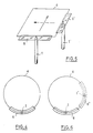
- the reference 1 designates the supply line, which is a coaxial line - therefore asymmetrical -, with a central conductor 2 forming the core of the cable and a peripheral conductor 3 forming mass and return conductor.
- This supply line leads to an antenna which includes a loop 4, a plane reflector 5 and a balancing element 6 in the form of a plate; each of these three elements is plane, and the planes of the three elements are mutually parallel.
- the loop 4 is preferably square in shape, and fully closed on itself. It is excited by the core 2 of the coaxial line, which is connected at a midpoint on one of the sides of the loop, so as to keep the symmetrical structure specific to loop antennas.
- a plane reflector 5 is arranged below the antenna; its dimensions are not critical, this reflector ideally extending to infinity.
- a balancing adapter element is provided, consisting of a metal plate 6 placed between the loop and the reflector, at a short distance from the loop, and connected to earth 3 of the supply line.
- This plate 6 has the effect of extending the mass of the coaxial line in the form of a ground plane ensuring coupling with the loop, because this plate is located in the close vicinity of one of the sides of the loop; in Figure 1 there is shown by arrows the direction of the field lines between the loop 4 and the reflector 6, thus visually showing how the transition is made between the asymmetric supply and the symmetrical radiating element.
- the plate 6 has the shape of an elongated rectangular plate extending parallel to one of the sides of the square formed by the loop 4, the length of the plate being of the same order as the length of this side, preferably slightly lower.
- FIG. 1 shows the respective preferred dimensions of the different elements, all given as a function of the wavelength of the central frequency of the antenna operating band.
- Figures 2 and 3 give the results of measurements made with an antenna having the characteristics and dimensions indicated in Figure 1.
- Figure 2 shows the variation of the ROS according to the frequency on the band 1250 - 1450 MHz, and we can see that the ROS always remains lower than 1.5 on the whole band, which allows to use in a way very suitable the antenna of the present invention for broadband transmission (in the case of FIG. 2, the frequency varies over ⁇ 7.5% around the central frequency).
- FIG. 3 shows the respective radiation diagrams: in the plane containing the electric field (curve E), that is to say in the plane perpendicular to the loop and to the side supplied by the coaxial line (this will be, for example , from the azimuth diagram, the loop and the side supplied by the coaxial line being vertical); in the plane, orthogonal to the previous one, containing the magnetic field (curve H, which would be the diagram in site in the preceding hypothesis); and the diagram corresponding to a cross polarization (curve X).
- curve E the electric field
- curve H which would be the diagram in site in the preceding hypothesis
- curve X the diagram corresponding to a cross polarization
- the loop is not necessarily square or rectangular; alternatively, it may include a curvilinear part in the vicinity of the excitation point, or even be completely circular as shown in FIG. 4, the plate 6 then being curved to follow the contour of the curvilinear part around the point of excitation.
- loop 4 can be attacked by a second coaxial 1 ′ situated on the loop at 90 ° relative to the first coaxial 1. It is then provided , as for the first coaxial, a plate 6 ′ forming a balancing element.
- the two coaxials can be used either selectively (one can then obtain, depending on the coaxial chosen for the excitation, a vertical or horizontal polarization), or simultaneously with phase shift of ⁇ / 2 between the two supply signals of the loop (on can then get circular polarization)
Landscapes
- Aerials With Secondary Devices (AREA)
- Variable-Direction Aerials And Aerial Arrays (AREA)
Abstract
Description
La présente invention concerne une antenne du type boucle à alimentation dissymétrique.The present invention relates to a loop type antenna with asymmetrical feed.
On connaît les caractéristiques des antennes boucle, notamment leur large bande passante et leur diagramme relativement ouvert, ce qui les fait utiliser principalement en réception.
Dans la majeure partie des cas, la boucle est utilisée seule, c'est à dire sans réflecteur associé, et elle est alimentée soit par une ligne bifilaire dont les deux conducteurs aboutissent aux deux extrémités de la boucle (qui n'est pas fermée sur elle-même), soit par une ligne coaxiale, la connexion de la boucle à la ligne se faisant alors avec interposition d'un boîtier symétriseur.
Les antennes boucle actuellement utilisées conviennent mal à une utilisation en émission en raison de leur ROS (Rapport d'Ondes Stationnaires) pénalisant pour l'énergie rayonnée.
De plus, si la sortie de l'émetteur comme c'est généralement le cas se fait sur une ligne coaxiale, l'utilisation du symétriseur augmente encore le ROS ; en outre, il ne permet un fonctionnement convenable que dans une bande de fréquences relativement étroite (autour de la fréquence d'accord du symétriseur), ce qui est incompatible avec une émission à large bande.We know the characteristics of loop antennas, especially their wide bandwidth and their relatively open diagram, which makes them used mainly in reception.
In most of the cases, the loop is used alone, that is to say without associated reflector, and it is supplied either by a two-wire line whose two conductors terminate at the two ends of the loop (which is not closed on itself), or by a coaxial line, the connection of the loop to the line then being made with the interposition of a balun housing.
The loop antennas currently used are ill-suited to use in transmission because of their ROS (Stationary Wave Report) penalizing for the radiated energy.
In addition, if the output of the transmitter as is generally the case is on a coaxial line, the use of the balun further increases the ROS; moreover, it allows suitable operation only in a relatively narrow frequency band (around the tuning frequency of the balun), which is incompatible with broadband transmission.
L'un des buts de la présente invention est de proposer une antenne de type boucle qui puisse être alimentée par une ligne coaxiale, notamment pour une utilisation en émission, en assurant une excellente adaptation tant en ce qui concerne le ROS que le diagramme de rayonnement, et ceci sur une bande de fréquences relativement large.One of the aims of the present invention is to provide a loop type antenna which can be supplied by a coaxial line, in particular for use in transmission, ensuring excellent adaptation both with regard to the ROS and the radiation pattern. , and this over a relatively wide frequency band.
De plus, et comme on le verra, l'invention permet de disposer d'une source rayonnante adaptée simple à réaliser et de faible coût, ce qui permet éventuellement de multiplier le nombre d'antennes de manière à former un réseau de grandes dimensions (antenne "dalle"), pour des puissances rayonnées importantes.In addition, and as will be seen, the invention makes it possible to have a suitable radiating source which is simple to produce and of low cost, which optionally makes it possible to multiply the number of antennas so as to form a large array ( "slab" antenna), for large radiated powers.
A cet effet, selon la présente invention, l'antenne, qui est alimentée par au moins une ligne coaxiale, comprend :
- un élément rayonnant en forme de boucle plane symétrique fermée sur elle-même, reliée à l'âme de la ligne coaxiale d'alimentation en un point de la boucle,
- un plan réflecteur s'étendant parallèlement au plan de la boucle et à distance de celle-ci, et
- au moins un élément symétriseur en forme de plaque métallique, disposée entre la boucle et le réflecteur et s'étendant parallèlement au plan de la boucle et à celui du réflecteur, et de forme générale correspondant sensiblement à celle de la partie de la boucle reliée à l'âme de la ligne coaxiale, cette plaque étant reliée à la masse de la ligne coaxiale d'alimentation.To this end, according to the present invention, the antenna, which is supplied by at least one coaxial line, comprises:
- a radiating element in the form of a symmetrical flat loop closed on itself, connected to the core of the coaxial supply line at a point of the loop,
a reflective plane extending parallel to the plane of the loop and at a distance therefrom, and
- At least one balancing element in the form of a metal plate, arranged between the loop and the reflector and extending parallel to the plane of the loop and to that of the reflector, and of general shape corresponding substantially to that of the part of the loop connected to the core of the coaxial line, this plate being connected to the ground of the coaxial supply line.
En outre, selon un certain nombre de caractéristiques avantageuses :
- ladite partie de boucle est un segment rectiligne, la plus grande dimension de la plaque rectangulaire étant sensiblement égale ou inférieure à la longueur de ce segment de boucle situé en regard ; de préférence, la boucle est alors de forme sensiblement carrée ;
- le rapport longueur/largeur de la plaque rectangulaire est au moins égal à 4 ;
- la distance du plan de la plaque au plan de la boucle est inférieure à un dixième de la longueur d'onde ;
- le rapport distance du plan de la plaque au plan de la boucle/distance du plan de la plaque au plan du réflecteur est compris entre environ 1:5 et 1:10 ;
- la distance du plan de la boucle au plan du réflecteur est sensiblement égale ou inférieure à une demi-longueur d'onde ;
- la boucle est alimentée, sélectivement ou simultanément par une seconde ligne coaxiale en un second point d'alimentation situé sensiblement orthogonalement sur la boucle par rapport au premier point d'alimentation.In addition, according to a number of advantageous features:
- Said loop portion is a rectilinear segment, the largest dimension of the rectangular plate being substantially equal to or less than the length of this loop segment located opposite; preferably, the loop is then of substantially square shape;
- the length / width ratio of the rectangular plate is at least equal to 4;
the distance from the plane of the plate to the plane of the loop is less than one tenth of the wavelength;
the ratio between the plane of the plate and the plane of the loop / distance from the plane of the plate to the plane of the reflector is between approximately 1: 5 and 1:10;
the distance from the plane of the loop to the plane of the reflector is substantially equal to or less than half a wavelength;
- The loop is fed, selectively or simultaneously by a second coaxial line at a second feed point located substantially orthogonally on the loop relative to the first feed point.
L'invention a également pour objet une antenne réseau formée d'un groupement ordonné d'une pluralité d'antennes ayant la structure caractéristique précitée, excitées simultanément, la boucle et la plaque de chaque antenne s'étendant au-dessus d'un plan réflecteur commun.The invention also relates to a network antenna formed by an ordered grouping of a plurality of antennas having the aforementioned characteristic structure, excited simultaneously, the loop and the plate of each antenna extending above a plane. common reflector.
D'autres caractéristiques et avantages de la présente invention apparaîtront à la lecture de la description détaillée ci-dessous, faite en référence aux dessins annexés sur lesquels :
- - la figure 1 est une vue schématique, en perspective, de l'antenne de la présente invention,
- - la figure 2 est une courbe montrant la variation du ROS sur une large plage de fréquences,
- - la figure 3 représente divers diagrammes de rayonnement relevés pour l'antenne de la figure 1,
- - la figure 4 est une vue en plan d'une variante de réalisation dans laquelle la boucle est circulaire,
- - la figure 5 est homologue de la figure 1, pour un mode de réalisation dans lequel la boucle est excitée séparément en deux points par deux coaxiaux différents, et
- - la figure 6 est homologue de la figure 4, dans le cas du mode de réalisation de la figure 5.
- FIG. 1 is a schematic perspective view of the antenna of the present invention,
- FIG. 2 is a curve showing the variation of the ROS over a wide frequency range,
- FIG. 3 represents various radiation patterns noted for the antenna of FIG. 1,
- FIG. 4 is a plan view of an alternative embodiment in which the loop is circular,
- FIG. 5 is homologous with FIG. 1, for an embodiment in which the loop is excited separately at two points by two different coaxials, and
- FIG. 6 is homologous to FIG. 4, in the case of the embodiment of FIG. 5.
Sur la figure 1, la référence 1 désigne la ligne d'alimentation, qui est une ligne coaxiale -donc dissymétrique-, avec un conducteur central 2 formant l'âme du câble et un conducteur périphérique 3 formant masse et conducteur de retour.
Cette ligne d'alimentation aboutit à une antenne qui comporte une boucle 4, un réflecteur plan 5 et un élément symétriseur 6 en forme de plaque ; chacun de ces trois éléments est plan, et les plans des trois éléments sont parallèles entre eux.
La boucle 4 est de préférence de forme carrée, et entièrement fermée sur elle-même. Elle est excitée par l'âme 2 de la ligne coaxiale, qui est reliée en un point médian de l'un des côtés de la boucle, de manière à conserver la structure symétrique propre aux antennes boucles.
Un réflecteur plan 5 est disposé au-dessous de l'antenne ; ses dimensions ne sont pas critiques, ce réflecteur s'étendant idéalement à l'infini.
Pour assurer la transition entre la structure symétrique boucle-réflecteur et la ligne d'alimentation dissymétrique, on prévoit un élément d'adaptation symétriseur constitué par une plaque métallique 6 disposée entre la boucle et le réflecteur, à faible distance de la boucle, et reliée à la masse 3 de la ligne d'alimentation.
Cette plaque 6 a pour effet de prolonger la masse de la ligne coaxiale sous forme d'un plan de masse assurant le couplage avec la boucle, du fait que cette plaque se trouve au voisinage étroit de l'un des côtés de la boucle ; sur la figure 1 on a représenté par des flèches la direction des lignes de champ entre la boucle 4 et le réflecteur 6, montrant ainsi visuellement comment est réalisée la transition entre l'alimentation dissymétrique et l'élément rayonnant symétrique. De préférence, la plaque 6 a la forme d'une plaque rectangulaire allongée s'étendant parallèlement à l'un des côtés du carré formé par la boucle 4, la longueur de la plaque étant du même ordre que la longueur de ce côté, de préférence légèrement inférieure.In FIG. 1, the
This supply line leads to an antenna which includes a
The
A
To ensure the transition between the symmetrical loop-reflector structure and the asymmetrical supply line, a balancing adapter element is provided, consisting of a
This
On a porté sur la figure 1 les dimensions respectives préférentielles des différents éléments, toutes données en fonction de la longueur d'onde de la fréquence centrale de la bande de fonctionnement de l'antenne.FIG. 1 shows the respective preferred dimensions of the different elements, all given as a function of the wavelength of the central frequency of the antenna operating band.
Les figures 2 et 3 donnent les résultats de mesures effectuées avec une antenne présentant les caractéristiques et les dimensions indiquées sur la figure 1.Figures 2 and 3 give the results of measurements made with an antenna having the characteristics and dimensions indicated in Figure 1.
La figure 2 montre la variation du ROS en fonction de la fréquence sur la bande 1250 - 1450 MHz, et l'on peut voir que le ROS reste toujours inférieur à 1,5 sur toute la bande, ce qui permet d'utiliser de façon très convenable l'antenne de la présente invention pour une émission à large bande (dans le cas de la figure 2, la fréquence varie sur ± 7,5 % autour de la fréquence centrale).Figure 2 shows the variation of the ROS according to the frequency on the band 1250 - 1450 MHz, and we can see that the ROS always remains lower than 1.5 on the whole band, which allows to use in a way very suitable the antenna of the present invention for broadband transmission (in the case of FIG. 2, the frequency varies over ± 7.5% around the central frequency).
La figure 3 montre les diagrammes de rayonnement respectifs : dans le plan contenant le champ électrique (courbe E), c'est à dire dans le plan perpendiculaire à la boucle et au côté alimenté par la ligne coaxiale (il s'agira, par exemple, du diagramme en azimut, la boucle et le côté alimenté par la ligne coaxiale étant verticaux); dans le plan, orthogonal au précédent, contenant le champ magnétique (courbe H, qui serait le diagramme en site dans l'hypothèse précédente); et le diagramme correspondant à une polarisation croisée (courbe X). Comme on le peut le voir, le gain de l'antenne reste homogène sur une ouverture angulaire relativement large.FIG. 3 shows the respective radiation diagrams: in the plane containing the electric field (curve E), that is to say in the plane perpendicular to the loop and to the side supplied by the coaxial line (this will be, for example , from the azimuth diagram, the loop and the side supplied by the coaxial line being vertical); in the plane, orthogonal to the previous one, containing the magnetic field (curve H, which would be the diagram in site in the preceding hypothesis); and the diagram corresponding to a cross polarization (curve X). As can be seen, the gain of the antenna remains uniform over a relatively wide angular opening.
On notera que la boucle n'est pas nécessairement carrée ou rectangulaire ; en variante, elle peut comprendre une partie curviligne au voisinage du point d'excitation, ou même être complètement circulaire comme représenté figure 4, la plaque 6 étant alors courbée pour suivre le contour de la partie curviligne autour du point d'excitation.Note that the loop is not necessarily square or rectangular; alternatively, it may include a curvilinear part in the vicinity of the excitation point, or even be completely circular as shown in FIG. 4, the
Par ailleurs, comme iliustré sur les figures 5 (boucle carrée) et 6 (boucle circulaire), la boucle 4 peut être attaquée par un second coaxial 1′ situé sur la boucle à 90° par rapport au premier coaxial 1. Il est alors prévu, comme pour le premier coaxial, une plaque 6′ formant élément symétriseur.
Les deux coaxiaux peuvent être utilisés soit sélectivement (on peut alors obtenir, selon le coaxial choisi pour l'excitation, une polarisation verticale ou horizontale), soit simultanément avec déphasage de ¶/2 entre les deux signaux d'alimentation de la boucle (on peut alors obtenir une polarisation circulaire)Furthermore, as illustrated in FIGS. 5 (square loop) and 6 (circular loop),
The two coaxials can be used either selectively (one can then obtain, depending on the coaxial chosen for the excitation, a vertical or horizontal polarization), or simultaneously with phase shift of ¶ / 2 between the two supply signals of the loop (on can then get circular polarization)
Enfin, il est possible de prévoir, au dessus d'un plan réflecteur commun, une pluralité d'ensembles boucle-plaque disposés de manière à former un réseau et alimentés simultanément (éventuellement avec un déphasage approprié) de manière à pouvoir rayonner une puissance plus importante et/ou à modifier le diagramme de rayonnement en jouant sur les déphasages relatifs d'excitation des différents éléments du réseau, comme cela est bien connu dans la technique.Finally, it is possible to provide, above a common reflecting plane, a plurality of loop-plate assemblies arranged so as to form a network and supplied simultaneously (possibly with an appropriate phase shift) so as to be able to radiate more power. important and / or to modify the radiation diagram by playing on the relative phase shifts of excitation of the various elements of the network, as is well known in the art.
Claims (9)
- un élément rayonnant en forme de boucle (4) plane symétrique fermée sur elle-même, reliée à l'âme (2) de la ligne coaxiale d'alimentation en un point de la boucle,
- un plan réflecteur (5) s'étendant parallèlement au plan de la boucle et à distance de celle-ci, et
- au moins un élément symétriseur en forme de plaque (6) métallique, disposée entre la boucle et le réflecteur et s'étendant parallèlement au plan de la boucle et à celui du réflecteur, et de forme générale correspondant sensiblement à celle de la partie de la boucle reliée à l'âme de la ligne coaxiale, cette plaque étant reliée à la masse (3) de la ligne coaxiale d'alimentation.1. A loop type antenna supplied by at least one coaxial line (1), characterized in that it comprises:
- a radiating element in the form of a loop (4) symmetrical planar closed on itself, connected to the core (2) of the coaxial supply line at a point of the loop,
a reflective plane (5) extending parallel to the plane of the loop and at a distance therefrom, and
- At least one balancing element in the form of a metal plate (6), disposed between the loop and the reflector and extending parallel to the plane of the loop and to that of the reflector, and of general shape corresponding substantially to that of the part of the loop connected to the core of the coaxial line, this plate being connected to the ground (3) of the coaxial supply line.
Applications Claiming Priority (2)
| Application Number | Priority Date | Filing Date | Title |
|---|---|---|---|
| FR8804389 | 1988-04-01 | ||
| FR8804389A FR2629644B1 (en) | 1988-04-01 | 1988-04-01 | BROADBAND LOOP ANTENNA WITH DISSYMMETRIC POWER SUPPLY, IN PARTICULAR AN EMISSION ANTENNA, AND NETWORK ANTENNA FORMED FROM A PLURALITY OF SUCH ANTENNAS |
Publications (1)
| Publication Number | Publication Date |
|---|---|
| EP0337841A1 true EP0337841A1 (en) | 1989-10-18 |
Family
ID=9364912
Family Applications (1)
| Application Number | Title | Priority Date | Filing Date |
|---|---|---|---|
| EP89400848A Ceased EP0337841A1 (en) | 1988-04-01 | 1989-03-24 | Broadband transmitting antenna loop with asymmetric feed and array of a plurality of these loops |
Country Status (3)
| Country | Link |
|---|---|
| US (1) | US4987423A (en) |
| EP (1) | EP0337841A1 (en) |
| FR (1) | FR2629644B1 (en) |
Families Citing this family (7)
| Publication number | Priority date | Publication date | Assignee | Title |
|---|---|---|---|---|
| JPH0993019A (en) * | 1995-09-27 | 1997-04-04 | Harada Ind Co Ltd | Window glass antenna for vehicle |
| US5706016A (en) * | 1996-03-27 | 1998-01-06 | Harrison, Ii; Frank B. | Top loaded antenna |
| US6911947B1 (en) * | 1999-09-08 | 2005-06-28 | Thomson Licensing S.A. | Method and apparatus for reducing multipath distortion in a television signal |
| CN1268036C (en) * | 2001-01-26 | 2006-08-02 | 科学技术研究院 | Low cross-polarization broadband suspended plate antennas |
| KR20040077052A (en) * | 2003-02-27 | 2004-09-04 | 한국전자통신연구원 | Wideband slot antenna and slot array antenna using the same |
| GB2438245B (en) * | 2006-05-18 | 2010-05-05 | Deltenna Ltd | Antenna element |
| TW200830632A (en) * | 2007-01-05 | 2008-07-16 | Advanced Connection Tech Inc | Circular polarized antenna |
Citations (5)
| Publication number | Priority date | Publication date | Assignee | Title |
|---|---|---|---|---|
| US2716191A (en) * | 1953-01-16 | 1955-08-23 | Walter E Knoop | Antenna |
| DE2245195A1 (en) * | 1971-11-26 | 1973-05-30 | Vorta Systems Inc | ANTENNA |
| DE2633757A1 (en) * | 1975-10-06 | 1977-04-14 | Ball Corp | MULTIPLE ANTENNA |
| US4191959A (en) * | 1978-07-17 | 1980-03-04 | The United States Of America As Represented By The Secretary Of The Army | Microstrip antenna with circular polarization |
| US4719470A (en) * | 1985-05-13 | 1988-01-12 | Ball Corporation | Broadband printed circuit antenna with direct feed |
Family Cites Families (4)
| Publication number | Priority date | Publication date | Assignee | Title |
|---|---|---|---|---|
| US4051477A (en) * | 1976-02-17 | 1977-09-27 | Ball Brothers Research Corporation | Wide beam microstrip radiator |
| US4162499A (en) * | 1977-10-26 | 1979-07-24 | The United States Of America As Represented By The Secretary Of The Army | Flush-mounted piggyback microstrip antenna |
| JPS57107610A (en) * | 1980-12-25 | 1982-07-05 | Nippon Telegr & Teleph Corp <Ntt> | Circular polarized wave cone beam antenna |
| US4554549A (en) * | 1983-09-19 | 1985-11-19 | Raytheon Company | Microstrip antenna with circular ring |
-
1988
- 1988-04-01 FR FR8804389A patent/FR2629644B1/en not_active Expired - Lifetime
-
1989
- 1989-03-24 US US07/328,447 patent/US4987423A/en not_active Expired - Fee Related
- 1989-03-24 EP EP89400848A patent/EP0337841A1/en not_active Ceased
Patent Citations (5)
| Publication number | Priority date | Publication date | Assignee | Title |
|---|---|---|---|---|
| US2716191A (en) * | 1953-01-16 | 1955-08-23 | Walter E Knoop | Antenna |
| DE2245195A1 (en) * | 1971-11-26 | 1973-05-30 | Vorta Systems Inc | ANTENNA |
| DE2633757A1 (en) * | 1975-10-06 | 1977-04-14 | Ball Corp | MULTIPLE ANTENNA |
| US4191959A (en) * | 1978-07-17 | 1980-03-04 | The United States Of America As Represented By The Secretary Of The Army | Microstrip antenna with circular polarization |
| US4719470A (en) * | 1985-05-13 | 1988-01-12 | Ball Corporation | Broadband printed circuit antenna with direct feed |
Also Published As
| Publication number | Publication date |
|---|---|
| FR2629644A1 (en) | 1989-10-06 |
| US4987423A (en) | 1991-01-22 |
| FR2629644B1 (en) | 1991-11-29 |
Similar Documents
| Publication | Publication Date | Title |
|---|---|---|
| EP3547450B1 (en) | Radiating element with circular polarisation implementing a resonance in a fabry-perot cavity | |
| EP0205212B1 (en) | Modular microwave antenna units and antenna composed of such units | |
| CA2243603C (en) | Radiating structure | |
| EP0520851B1 (en) | Antenna combination for reception of signals from satellites and groundstations, particularly for the reception of digital audio broadcasting signals | |
| EP2869400B1 (en) | Bi-polarisation compact power distributor, network of a plurality of distributors, compact radiating element and planar antenna having such a distributor | |
| FR2810163A1 (en) | IMPROVEMENT TO ELECTROMAGNETIC WAVE EMISSION / RECEPTION SOURCE ANTENNAS | |
| FR2652453A1 (en) | COAXIAL ANTENNA HAVING A PROGRESSIVE WAVE POWER TYPE. | |
| EP0064313A1 (en) | Circularly polarised microwave radiating element and flat microwave antenna using an array of such elements | |
| EP0430745B1 (en) | Circular polarized antenna, particularly for array antenna | |
| EP1941580A1 (en) | Transmitting/receiving antenna with radiation diversity | |
| EP0337841A1 (en) | Broadband transmitting antenna loop with asymmetric feed and array of a plurality of these loops | |
| EP2006954B1 (en) | Communication device for a railway vehicle | |
| FR2700067A1 (en) | Dual polarized plated antenna and corresponding transmitting / receiving device. | |
| EP1949496B1 (en) | Flat antenna system with a direct waveguide access | |
| FR2552273A1 (en) | Omnidirectional microwave antenna | |
| FR2678438A1 (en) | LINEAR NETWORK ANTENNA. | |
| EP0477102B1 (en) | Directional network with adjacent radiator elements for radio communication system and unit with such a directional network | |
| EP0083885B1 (en) | Selective tunable magnetostatic bulk wave device | |
| CA2342953C (en) | Dual-band microwave antenna element | |
| FR3022404A1 (en) | SATELLITE TELECOMMUNICATION FLAT ANTENNA | |
| WO2023218008A1 (en) | Low-profile antenna with two-dimensional electronic scanning | |
| FR2751138A1 (en) | Microstrip array antenna | |
| FR3108797A1 (en) | WIDE BAND DIRECTIVE ANTENNA WITH LONGITUDINAL EMISSION | |
| FR2934088A1 (en) | Antenna i.e. helix antenna, for radio transmission in e.g. satellite application, has reflecting plane to reflect part of radio wave in circularly polarized manner, where reflected and non-reflected parts are emitted in half-plane of space | |
| FR2710458A1 (en) | Two-wire planar antenna |
Legal Events
| Date | Code | Title | Description |
|---|---|---|---|
| PUAI | Public reference made under article 153(3) epc to a published international application that has entered the european phase |
Free format text: ORIGINAL CODE: 0009012 |
|
| AK | Designated contracting states |
Kind code of ref document: A1 Designated state(s): DE GB IT NL |
|
| 17P | Request for examination filed |
Effective date: 19900207 |
|
| 17Q | First examination report despatched |
Effective date: 19920713 |
|
| STAA | Information on the status of an ep patent application or granted ep patent |
Free format text: STATUS: THE APPLICATION HAS BEEN REFUSED |
|
| RAP1 | Party data changed (applicant data changed or rights of an application transferred) |
Owner name: THOMSON-CSF |
|
| 18R | Application refused |
Effective date: 19931115 |