EP0880193A1 - Antennenstrahler für Mikrowellensendung und empfang - Google Patents
Antennenstrahler für Mikrowellensendung und empfang Download PDFInfo
- Publication number
- EP0880193A1 EP0880193A1 EP98401216A EP98401216A EP0880193A1 EP 0880193 A1 EP0880193 A1 EP 0880193A1 EP 98401216 A EP98401216 A EP 98401216A EP 98401216 A EP98401216 A EP 98401216A EP 0880193 A1 EP0880193 A1 EP 0880193A1
- Authority
- EP
- European Patent Office
- Prior art keywords
- waveguide
- source according
- signals
- transducer
- reception
- Prior art date
- Legal status (The legal status is an assumption and is not a legal conclusion. Google has not performed a legal analysis and makes no representation as to the accuracy of the status listed.)
- Granted
Links
Images
Classifications
-
- H—ELECTRICITY
- H01—ELECTRIC ELEMENTS
- H01P—WAVEGUIDES; RESONATORS, LINES, OR OTHER DEVICES OF THE WAVEGUIDE TYPE
- H01P1/00—Auxiliary devices
- H01P1/20—Frequency-selective devices, e.g. filters
- H01P1/213—Frequency-selective devices, e.g. filters combining or separating two or more different frequencies
- H01P1/2131—Frequency-selective devices, e.g. filters combining or separating two or more different frequencies with combining or separating polarisations
-
- H—ELECTRICITY
- H01—ELECTRIC ELEMENTS
- H01P—WAVEGUIDES; RESONATORS, LINES, OR OTHER DEVICES OF THE WAVEGUIDE TYPE
- H01P1/00—Auxiliary devices
- H01P1/16—Auxiliary devices for mode selection, e.g. mode suppression or mode promotion; for mode conversion
- H01P1/161—Auxiliary devices for mode selection, e.g. mode suppression or mode promotion; for mode conversion sustaining two independent orthogonal modes, e.g. orthomode transducer
Definitions
- the invention relates to an antenna source for the emission and reception of polarized microwave waves.
- band C used today for certain satellite communications, from 3.625 to 4.2 GHz for reception and 5.85 to 6.425 GHz for transmission will be expanded down for reception (3.4 to 4.2 GHz) and down high (5.85 to 6.65 GHz) for transmission.
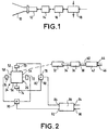
- FIG. 1 a source diagram antenna usable for transmitting and receiving signals in conventional C-band, i.e. with bandwidths of 575 MHz for transmission and reception.
- This antenna source known comprises a radiating element such as a horn 10 connected, via an adaptation section 12 and a guide of circular section waves 14, to a polarizer 16 intended for convert, on the one hand, the signals received into circular polarization into signals in linear polarization and, on the other hand, signals to be transmitted from linear polarization to polarization circular.
- the polarizer 16 is connected to a transducer 18 for separate the transmit and receive frequencies.
- This transducer comprises a waveguide of circular section whose surface exterior has longitudinal direction slots - that is to say whose largest dimension is parallel to the axis of the guide - connected to other waveguides (not shown) and filtering means (also not shown) eliminating the transmission frequencies and allowing reception frequencies to pass.
- the end of the waveguide of the transducer 18 which is opposite to that connected to polarizer 16 receives the signals to issue.
- the transmission channel includes filtering means for eliminate reception frequencies and, generally, means of orthogonal polarization.
- the invention overcomes these drawbacks.
- the antenna source according to the invention is characterized in that to transmit and receive wide signals bands, the transducer separating the emission and reception includes a square section waveguide or a guide of square or circular section (or another section) with ribs or corrugations perpendicular to the direction of propagation.
- this transducer is connected to the emission channel thanks to a section waveguide circular penetrating inside the waveguide of the transducer.
- This arrangement optimizes the separation between transmit and receive signals. This separation is further improved if there is provision at the end of the waveguide circular, inside the waveguide of the transducer, a iris, for example in the form of a double slit.
- the transducer has a waveguide of square section is advantageously provided, on each of its sides, a rectangular or slow opening, the long side is advantageously perpendicular to the axis of the waveguide.
- These slots allow extracting reception signals; they are associated with filtering means to eliminate the frequencies resignation.
- connection of the radiating element to the transducer separating the transmission and reception frequencies is such that it maintains the polarization state of the transmitted signals.
- the transmitted or received signals must undergo a conversion from their polarization state (circular to linear or linear in circular)
- a corresponding polarizer is provided in the transmission and / or reception channel, opposite to the radiating element with respect to the transducer. This provision also works well for large transmit and receive bands.
- slots of two opposite faces are, in one embodiment, connected to the Respective inputs of a "Magic tee" type adder.
- the signal received being circularly polarized the output of each of these adders provides the reception signal with a linear polarization of determined direction, the outputs of two magic tees being signals whose polarization vectors are perpendicular to each other.
- a coupler is advantageously used 3db / 90 °, in particular of the "Riblet" type.
- Such a coupler includes two rectangular section waveguides that connect in a junction area of parallelepiped shape, each waveguide comprising an incoming branch and an outgoing branch of the junction area. The latter has a height equal to the short side of the section of each waveguide and one width equal to twice the long side of said section.
- such a coupler is used in which the junction zone has, at least on a large wall, a elongated projection in the direction transverse to the spread.
- the corresponding projections in the junction area are either circular or elongated in the longitudinal direction.
- each of these ribs having, preferably a height which gradually decreases to inside each branch.
- a receiving duplexer For transmission, when it is necessary to issue right and / or left circularly polarized signals from linear polarized signals, a receiving duplexer is used the signals emitted in orthogonal linear polarizations and a polarizer which transforms linearly polarized signals into circularly polarized signals.
- a polarizer of the type "Septum" which combines the duplexer and polarizer functions has two waveguides of semicircular section receiving linearly polarized signals which converge on a circular section output waveguide.
- a wall or blade of longitudinal direction and decreasing in height in direction radial In the output waveguide, from the junction area input waveguides, a wall or blade of longitudinal direction and decreasing in height in direction radial. This wall extends along the axis of the waveguide of exit.
- the decrease in the height of the blade is either progressive, or, preferably, by jumps, that is to say in stairs. We found that we got the best results with such steps and that the number of these steps had an influence on the bandwidth of the polarizer. In general the more the number of steps increases the more the bandwidth of the polarizer is important.
- the embodiment of the invention that we are going to describe in relation to the figures concerns an antenna source broadband C transmission and reception.
- the frequencies are from 3.4 to 4.2 GHz and for transmission, the frequencies are 5.85 to 6.65 GHz.
- the reception frequency band extends on 800 MHz. The same is true for the frequency band resignation.
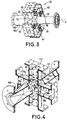
- the antenna source shown in Figure 2 includes a transducer 24 comprising a waveguide 26 of section square which, in the figure, is represented in cross section, that is to say perpendicular to the axis of propagation.
- a transducer 24 comprising a waveguide 26 of section square which, in the figure, is represented in cross section, that is to say perpendicular to the axis of propagation.
- Moon of the ends of this waveguide 26 is connected directly to a propagation horn (not shown).
- a propagation horn not shown.
- This connection can however include an element non-radiating other than a polarizer, by temple an extractor mode used to control a front antenna follow the trajectory of a satellite.
- the end 30 (FIG. 3) of the waveguide 26 which is opposite the end 28 connected to the horn is connected to a waveguide 32 of circular section receiving, via of a waveguide 34 of square section, the signals emission in right circular polarization and circular polarization left supplied by a polarizer 36.
- the purpose of the polarizer 36 is to transform the signals input with linear polarization into output signals with polarization circular.
- the input 38 of the polarizer 36 is connected to the output 40 of a duplexer 42 having two inputs, 44 and 46 respectively, receiving linearly polarized signals which must be transformed into polarized signals right circular and left circular polarization.
- Entrance 44 receives the signals which must be transformed into signals to right circular polarization and input 46 receives signals to be transformed into circularly polarized signals left.
- the duplexer 42 and polarizer 36 form a single element 50 constituting a polarizer of the "Septum" type, which will be described more far in relation to Figures 5 and 6.
- the lateral faces 52, 54, 56 and 58 of the waveguide 26 have rectangular openings, or slots, to which are connected reduced waveguides having the same rectangular section.
- the guides waves 60, 62, 64 and 66 have the position along the x axis of guide 26. It is important to note that the largest dimension slots, and therefore rectangular waveguides 60, 62, 64 and 66, is perpendicular to the x axis. In other words the rectangular openings extend transversely to to the direction of propagation.
- Waveguides 60, 62, 64 and 66 are equipped with filters, respectively 70, 72, 74 and 76 ( Figure 2), to remove transmit frequencies and pass frequencies reception.
- the rectangular waveguides associated with the faces opposite 52 and 56 of the guide 26 are connected to the two inputs, 78 and 80 respectively, of a "magic tee" 82 (figure 2) whose output is connected to the first input 84 of a coupler 86 of the 3db / 90 ° type.
- the rectangular waveguides associated with the opposite sides 54 and 58 are connected to the respective inputs of a second "magic tee" 90 whose output is connected to the second input 92 of coupler 86.
- the coupler 86 receives, On its first input 84, a signal of a linear polarization of a first direction and, on its second input 92, a signal of linear polarization orthogonal. These signals are the two components of the wave at right and left circular polarization in the source. He gives on its outputs, respectively 94 and 96, signals which represent and differentiate the two circular polarizations orthogonal. For example, on output 94 the signal represents right circular polarization and on output 96 the signal represents the left circular polarization. An example of such coupler will be described later in relation to FIGS. 7 to 9.
- the square section of the waveguide 26 also contributes to expand the transmit and receive bands.
- the waveguide 26 has, on its internal face, corrugations, that is to say, ribs extending perpendicular to the x axis.
- the transducer 24 comprises, in place of the guide 26 of square section, a waveguide of circular section also with corrugations to broaden the band with respect to a waveguide devoid of such corrugations.
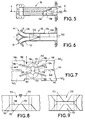
- the waveguide 26 is connected by its front face 28 to a waveguide 100 (FIG. 4) ensuring the transition between the 26 square section waveguide and the section waveguide circular cone.
- the waveguide 32 of circular section for the connection to the transmission channel ends, inside the guide of waves 26, by an iris 102 which, in the example, has the shape of a cross, that is to say of two perpendicular slots 104 and 106.
- the iris 102 short-circuits the reception frequencies.
- This ring 108 in combination with the iris 102, aims to reflect the signals of reception towards the slots of the lateral walls of the guide 26 and, thus, preventing reception signals from entering the emission channel.
- the circular waveguide 32 of the emission channel has other iris 110, 112 in the form of rings having a role impedance matching for the transmission frequencies included between 5.85 and 6.65 GHz.
- irises 114, 116 and 118 are also provided in each reduced rectangular section guide of the reception channel, for example in the waveguide 60 (FIG. 4).
- the irises 116 and 118 are each formed from of two rectangular plates or ribs projecting from the internal faces of the short sides of the waveguide 60. These ribs, which are referenced, respectively 116 1 and 116 2 for the iris 116, are perpendicular to the large faces 117 of the guide 60.
- iris 114 the closest to the corresponding slot (not visible in Figure 4) of the waveguide 26, is formed from two plates 114 1 and 114 2 also perpendicular to the small faces of the guide waves 60, but parallel to the large faces 117.
- Iris 114, 116 and 118 constitute the filtering means allowing to reject the frequencies of emission and pass reception frequencies.
- Figures 5 and 6 represent a Septum polarizer in the emission channel of the antenna shown in Figure 2.
- Septum type polarizer 50 has two guides of input waves 130 and 132. Input 44 is at the end waveguide 130 and inlet 46 is at the end of the guide of waves 132 ( Figures 2 and 6). In the vicinity of the entrances the guides are of rectangular section and are then of semi-circular section.
- These two waveguides 130 and 132 are connected continuously to a waveguide 134 of circular section, of which the diameter is equal to the diameter of the section of each of the semicircular guides 130 and 132.
- a central wall or blade 136 is provided, the plane of which contains the axis of the waveguide 134.
- its height, in the radial direction is equal to the internal diameter of guide 134.
- the width of this wall 136 decreases by saints, that is to say that its end section has steps. In the example, four steps are planned, respectively 140, 142, 144 and 146.
- the quality of the polarization circular i.e. the ellipticity rate, depends on the cutting of the end 138, in particular of the number of steps and length (in axial direction) and height (in radial direction) of each of these steps. In particular, we found that the higher the number of steps, the more bandwidth of the polarizer is wide. We will also note that the lengths and heights of the steps are uneven.
- FIGS 7 to 9 represent an embodiment of the coupler 86 in the path of reception.
- a 3db / 90 ° coupler of the type "Riblet" (figure 2), is such that a signal applied to an input 84 is transmitted according to two signals of equal amplitudes on the outputs 94 and 96, these output signals having a phase shift 90 ° to each other.
- a signal applied on the second input 92 is transmitted with equal amplitudes on outputs 94 and 96 and with a 90 ° phase shift between these output signals.
- Such a coupler comprises two waveguides 160 and 162 which are connected according to a junction zone 164.
- These guides waves have a rectangular section and are arranged so such as their small faces 166 and 168, corresponding to the short sides of the section, are adjacent and only in the area junction 164 these faces or walls are removed.
- the junction zone has a floor wall 170 and a ceiling wall 172 (FIG. 8).
- the width of these walls - i.e. their dimension perpendicular to the propagation y and parallel to the large faces of the guides 160 and 162 - is equal to twice the largest dimension of the rectangular section of each waveguide 160, 162.
- the height of the junction area i.e. the distance between the walls 170 and 172, is equal to the short side of the section of guides 160 and 162.
- the floor wall 170 has a projection 174 of which base 176 has a curvilinear shape elongated transversely to the direction Y of propagation (figure 7).
- This base 176 of the projection 174 occupies a large part, of the order of 75% of the floor area 170.
- the top 178 of this projection 174 is of substantially smaller dimensions than those of base 176. This top is also elongated transversely to the Y direction of propagation.
- the base and the top of the projection are centered relative to the junction zone 164.
- the projection 174 is extended by ribs, respectively 180, 182, 184 and 186.
- ribs respectively 180, 182, 184 and 186.
- the rib 180 is constituted by a wall perpendicular to the floor 170. Inside the junction zone 164 the height of this rib 180 is the same as the height of the projection 174. This rib 180 is directed towards the branch of input 160 1 of the waveguide 160 and it partially penetrates this branch 160 1 . In this branch its height gradually decreases. In other words, the end of the rib 180 has the shape of a wedge or bevel 190. Opposite the bevel 190, the rib 180 is connected to the end 192, facing the waveguide 160, from the top 178 of the projection 174.
- the rib 184 is directed towards the outlet branch 160 2 of the waveguide 160.
- the rib 182 is directed towards the inlet branch 162 1 of the waveguide 162 and the rib 186 is directed towards the outlet branch 162 2 of this same waveguide 162.
- the ribs 182 and 186 are connected to the end 194 of the apex 178 of the projection which is opposite to the end 192 to which the two other ribs 180 and 184 are connected.
- An adjustment screw 196 is provided in the ceiling 172 near its edge 198.
- Another adjustment screw 200 is located in the center of the ceiling 172. These screws allow adjustment of the coupling between the outgoing waves, i.e. an adjustment of the relative amplitudes of the waves.
- the projection 174 elongated transversely at direction Y of signal propagation allowed to keep the equal properties of the amplitudes of the output to within 0.1 dB over a wide frequency band and, in in all cases, on the 800 MHz of the receiving C band.
- the ribs 180, 182, 184 and 186 further significantly improve the quality of the coupler on the desired bandwidth.
- the dimensions of the zone 164 are of the same order of magnitude as the dimensions of the corresponding zone of a conventional Riblet coupler. In a manner known per se, the properties of the coupler result from the fact that the modes TE 10 and TE 20 coexist in the junction zone 164.
- the TE 10 mode is transformed into a TE 10 U-shaped mode, which gives it a more stationary guided wavelength ⁇ G and a greater bandwidth of use in relation to the dimensions of the U.
- the ceiling 172 of the junction zone 164 has a projection 210 analogous to projection 174 and which is also extended by four ribs similar to the corresponding associated ribs to the projection 174.
- the dimensions and arrangement of the projection 210 and associated ribs are the same as those of the projection 174 and its corresponding ribs.
- the projection 174 and, optionally, the projection 210 is not constituted by a continuous element but by a set of projections such as nipples sufficiently close together to give the same result as a continuous projection.
- the emission one can also foresee the use a duplexer and a polarizer turned 90 °, the emission taking place with linear polarization signals orthogonal.
- the source has a number of accesses lower than the four accesses provided in the examples described above (two transmitting accesses and two receiving accesses). In in this case, the unused accesses will be loaded.
- the antenna source described applies in particular telecommunications antennas with a diameter between 1 and 32 meters or more.
Applications Claiming Priority (2)
| Application Number | Priority Date | Filing Date | Title |
|---|---|---|---|
| FR9706172A FR2763749B1 (fr) | 1997-05-21 | 1997-05-21 | Source d'antenne pour l'emission et la reception d'ondes hyperfrequences polarisees |
| FR9706172 | 1997-05-21 |
Publications (2)
| Publication Number | Publication Date |
|---|---|
| EP0880193A1 true EP0880193A1 (de) | 1998-11-25 |
| EP0880193B1 EP0880193B1 (de) | 2003-08-27 |
Family
ID=9507058
Family Applications (1)
| Application Number | Title | Priority Date | Filing Date |
|---|---|---|---|
| EP98401216A Expired - Lifetime EP0880193B1 (de) | 1997-05-21 | 1998-05-20 | Antennenstrahler für Mikrowellensendung und empfang |
Country Status (10)
| Country | Link |
|---|---|
| US (1) | US6166699A (de) |
| EP (1) | EP0880193B1 (de) |
| JP (1) | JPH1117402A (de) |
| CN (1) | CN1202746A (de) |
| CA (1) | CA2235792A1 (de) |
| DE (1) | DE69817445D1 (de) |
| EA (1) | EA000492B1 (de) |
| FR (1) | FR2763749B1 (de) |
| ID (1) | ID20322A (de) |
| NO (1) | NO982232L (de) |
Cited By (3)
| Publication number | Priority date | Publication date | Assignee | Title |
|---|---|---|---|---|
| EP2058896A1 (de) * | 2007-11-09 | 2009-05-13 | Thales | Verfahren zur Herstellung einer als dicken Platte elektrogeformten Monoblock-Mikrowelle |
| EP2159870A1 (de) * | 2008-08-29 | 2010-03-03 | Astrium GmbH | Signal-Verzweigung zur Verwendung in einem Kommunikationssystem |
| WO2011110902A1 (en) | 2010-03-12 | 2011-09-15 | Andrew Llc | Dual polarized reflector antenna assembly |
Families Citing this family (18)
| Publication number | Priority date | Publication date | Assignee | Title |
|---|---|---|---|---|
| US6870512B2 (en) | 2001-03-02 | 2005-03-22 | Mitsubishi Denki Kabushiki Kaisha | Antenna device for conducting two-axial scanning of an azimuth and elevation |
| DE10126468B4 (de) * | 2001-05-31 | 2007-07-05 | Eads Deutschland Gmbh | Schlitzantenne |
| US6661309B2 (en) * | 2001-10-22 | 2003-12-09 | Victory Industrial Corporation | Multiple-channel feed network |
| FR2831997B1 (fr) | 2001-11-07 | 2004-01-16 | Thomson Licensing Sa | Module guide d'ondes separateur en frequence a polarisation circulaire double et emetteur-recepteur le comportant |
| FR2833763B1 (fr) * | 2001-12-14 | 2005-07-01 | Manuf D App Electr De Cahors M | Guide d'ondes en deux parties assemblees l'une contre l'autre |
| JP4060228B2 (ja) | 2003-04-04 | 2008-03-12 | 三菱電機株式会社 | 導波管形偏分波器 |
| JP4011511B2 (ja) * | 2003-04-04 | 2007-11-21 | 三菱電機株式会社 | アンテナ装置 |
| US6943744B1 (en) | 2003-07-09 | 2005-09-13 | Patriot Antenna Systems, Inc. | Waveguide diplexing and filtering device |
| CN101872901A (zh) | 2009-04-23 | 2010-10-27 | 安德鲁有限责任公司 | 单元微波天线馈电装置及其制造方法 |
| EP2815454A2 (de) | 2012-02-17 | 2014-12-24 | Pro Brand International (Europe) Limited | Mehrbandige datensignalempfangs- und/oder -sendevorrichtung |
| GB201602524D0 (en) * | 2016-02-12 | 2016-03-30 | Filtronic Broadband Ltd | A millimetre wave transceiver |
| RU169535U1 (ru) * | 2016-04-22 | 2017-03-22 | Федеральное государственное автономное образовательное учреждение высшего образования "Уральский федеральный университет имени первого Президента России Б.Н. Ельцина" | Возбудитель волны те01 |
| US10816661B2 (en) * | 2016-06-08 | 2020-10-27 | Rosemount Aerospace Inc. | Airborne ice detector using quasi-optical radar |
| RU2626726C1 (ru) * | 2016-07-12 | 2017-07-31 | Акционерное общество "Концерн воздушно-космической обороны "Алмаз-Антей"(АО "Концерн ВКО "Алмаз-Антей") | Компактная 90-градусная скрутка в прямоугольном волноводе |
| RU2647203C2 (ru) * | 2016-08-09 | 2018-03-14 | Российская Федерация, от имени которой выступает Государственная корпорация по космической деятельности "РОСКОСМОС" | Частотно-поляризационный селектор |
| CN110867644B (zh) * | 2019-11-11 | 2021-01-19 | 中国电子科技集团公司第十四研究所 | 一种双频段多极化共口径同轴波导缝隙天线 |
| US11851193B2 (en) | 2020-11-20 | 2023-12-26 | Rosemount Aerospace Inc. | Blended optical and vane synthetic air data architecture |
| US11686742B2 (en) | 2020-11-20 | 2023-06-27 | Rosemount Aerospace Inc. | Laser airspeed measurement sensor incorporating reversion capability |
Citations (6)
| Publication number | Priority date | Publication date | Assignee | Title |
|---|---|---|---|---|
| US3731236A (en) * | 1972-08-17 | 1973-05-01 | Gte Sylvania Inc | Independently adjustable dual polarized diplexer |
| US3955202A (en) * | 1975-04-15 | 1976-05-04 | Macrowave Development Laboratories, Inc. | Circularly polarized wave launcher |
| EP0041077A2 (de) * | 1980-05-30 | 1981-12-09 | ANT Nachrichtentechnik GmbH | Antennenspeisesystem für eine nachführbare Antenne |
| GB2117980A (en) * | 1982-03-25 | 1983-10-19 | Italiana Esercizio Telefon | Dual polarisation signal waveguide device |
| GB2194859A (en) * | 1986-09-12 | 1988-03-16 | Ca Minister Nat Defence | Antenna system |
| EP0518218A1 (de) * | 1991-06-11 | 1992-12-16 | Siemens Aktiengesellschaft | Mikrowellen-Kopplerpolarisator |
Family Cites Families (5)
| Publication number | Priority date | Publication date | Assignee | Title |
|---|---|---|---|---|
| US3500419A (en) * | 1966-09-09 | 1970-03-10 | Technical Appliance Corp | Dual frequency,dual polarized cassegrain antenna |
| DE2443166C3 (de) * | 1974-09-10 | 1985-05-30 | ANT Nachrichtentechnik GmbH, 7150 Backnang | Systemweiche zur Trennung zweier Signale, die aus je zwei doppelt polarisierten Frequenzbändern bestehen |
| US4162463A (en) * | 1977-12-23 | 1979-07-24 | Gte Sylvania Incorporated | Diplexer apparatus |
| JPS54114156A (en) * | 1978-02-27 | 1979-09-06 | Mitsubishi Electric Corp | Branching filter |
| US5003321A (en) * | 1985-09-09 | 1991-03-26 | Sts Enterprises, Inc. | Dual frequency feed |
-
1997
- 1997-05-21 FR FR9706172A patent/FR2763749B1/fr not_active Expired - Fee Related
-
1998
- 1998-05-15 NO NO982232A patent/NO982232L/no not_active Application Discontinuation
- 1998-05-18 ID IDP980723A patent/ID20322A/id unknown
- 1998-05-20 DE DE69817445T patent/DE69817445D1/de not_active Expired - Lifetime
- 1998-05-20 CA CA002235792A patent/CA2235792A1/fr not_active Abandoned
- 1998-05-20 EP EP98401216A patent/EP0880193B1/de not_active Expired - Lifetime
- 1998-05-20 CN CN98108862.7A patent/CN1202746A/zh active Pending
- 1998-05-20 US US09/081,515 patent/US6166699A/en not_active Expired - Lifetime
- 1998-05-20 EA EA199800396A patent/EA000492B1/ru not_active IP Right Cessation
- 1998-05-21 JP JP10140013A patent/JPH1117402A/ja active Pending
Patent Citations (6)
| Publication number | Priority date | Publication date | Assignee | Title |
|---|---|---|---|---|
| US3731236A (en) * | 1972-08-17 | 1973-05-01 | Gte Sylvania Inc | Independently adjustable dual polarized diplexer |
| US3955202A (en) * | 1975-04-15 | 1976-05-04 | Macrowave Development Laboratories, Inc. | Circularly polarized wave launcher |
| EP0041077A2 (de) * | 1980-05-30 | 1981-12-09 | ANT Nachrichtentechnik GmbH | Antennenspeisesystem für eine nachführbare Antenne |
| GB2117980A (en) * | 1982-03-25 | 1983-10-19 | Italiana Esercizio Telefon | Dual polarisation signal waveguide device |
| GB2194859A (en) * | 1986-09-12 | 1988-03-16 | Ca Minister Nat Defence | Antenna system |
| EP0518218A1 (de) * | 1991-06-11 | 1992-12-16 | Siemens Aktiengesellschaft | Mikrowellen-Kopplerpolarisator |
Cited By (6)
| Publication number | Priority date | Publication date | Assignee | Title |
|---|---|---|---|---|
| EP2058896A1 (de) * | 2007-11-09 | 2009-05-13 | Thales | Verfahren zur Herstellung einer als dicken Platte elektrogeformten Monoblock-Mikrowelle |
| FR2923657A1 (fr) * | 2007-11-09 | 2009-05-15 | Thales Sa | Procede de fabrication d'une source hyperfrequence monobloc electroformee a lame epaisse |
| EP2159870A1 (de) * | 2008-08-29 | 2010-03-03 | Astrium GmbH | Signal-Verzweigung zur Verwendung in einem Kommunikationssystem |
| WO2011110902A1 (en) | 2010-03-12 | 2011-09-15 | Andrew Llc | Dual polarized reflector antenna assembly |
| EP2545612A1 (de) * | 2010-03-12 | 2013-01-16 | Andrew LLC | Doppelt polarisierte reflektorantennengruppe |
| EP2545612A4 (de) * | 2010-03-12 | 2014-06-25 | Andrew Llc | Doppelt polarisierte reflektorantennengruppe |
Also Published As
| Publication number | Publication date |
|---|---|
| FR2763749B1 (fr) | 1999-07-23 |
| EA000492B1 (ru) | 1999-08-26 |
| US6166699A (en) | 2000-12-26 |
| EP0880193B1 (de) | 2003-08-27 |
| EA199800396A1 (ru) | 1998-12-24 |
| NO982232D0 (no) | 1998-05-15 |
| FR2763749A1 (fr) | 1998-11-27 |
| CN1202746A (zh) | 1998-12-23 |
| JPH1117402A (ja) | 1999-01-22 |
| DE69817445D1 (de) | 2003-10-02 |
| ID20322A (id) | 1998-11-26 |
| CA2235792A1 (fr) | 1998-11-21 |
| NO982232L (no) | 1998-11-23 |
Similar Documents
| Publication | Publication Date | Title |
|---|---|---|
| EP0880193B1 (de) | Antennenstrahler für Mikrowellensendung und empfang | |
| CA2869648C (fr) | Repartiteur de puissance compact bipolarisation, reseau de plusieurs repartiteurs, element rayonnant compact et antenne plane comportant un tel repartiteur | |
| EP2195877B1 (de) | Omt-breitband- und multiband-/sende- und empfangs-/kopplungs- und trennvorrichtung für hochfrequenz-telekommunikationsantennen | |
| FR2623020A1 (fr) | Dispositif d'excitation d'un guide d'onde en polarisation circulaire par une antenne plane | |
| FR2524209A1 (fr) | Dispositif guide d'ondes, capable de separer des signaux de radiofrequence a double bande et double polarisation | |
| FR2831997A1 (fr) | Module guide d'ondes separateur en frequence a polarisation circulaire double et emetteur-recepteur le comportant | |
| CA2869652A1 (fr) | Repartiteur de puissance comportant un coupleur en te dans le plan e, reseau rayonnant et antenne comportant un tel reseau rayonnant | |
| EP0098192B1 (de) | Multiplexanordnung zum Zusammenfügen von zwei Frequenzbändern | |
| FR2850793A1 (fr) | Transition entre un circuit micro-ruban et un guide d'onde et unite exterieure d'emission reception incorporant la transition | |
| EP3176875B1 (de) | Aufbau einer aktiven hybriden rekonfigurierbaren strahlbildungsantenne | |
| FR2859824A1 (fr) | Antenne a diversite de polarisation | |
| EP0377155B1 (de) | Doppelfrequenz strahlende Vorrichtung | |
| FR2824425A1 (fr) | Coupleur coaxial a large bande de jonction a mode orthogonal | |
| FR2723801A1 (fr) | Diplexeur a intervalle d'un octave entre bandes. | |
| EP0068940B1 (de) | Primärstrahler für Frequenz-Doppelausnutzung | |
| FR2463520A1 (fr) | Reseau quadriporte pour la separation de deux signaux constitues par des bandes de frequences a double polarisation | |
| EP0430136A1 (de) | Bandsperrfilter für Mikrowellenhohlleiter | |
| EP3035445B1 (de) | Anschlusskoppler mit orthogonalmodus, und entsprechender polarisations- und frequenztrennschalter | |
| WO2024047573A1 (fr) | Jonction orthomode à six ports | |
| EP0093058B1 (de) | Mikrowellen-Speisevorrichtung für rotationssymmetrischen Doppelbanderreger mit Rillen | |
| EP2092592B1 (de) | Orthogonalmodus-verbindungskoppler mit ultrabreiter betriebsbandbreite | |
| FR2705167A1 (fr) | Antenne plaquée large bande à encombrement réduit, et dispositif d'émission/réception correspondant. | |
| EP3811458A1 (de) | Hochfrequenzerreger einer empfangs- und sendeantenne | |
| FR2722032A1 (fr) | Dispositif de couplage en anneau |
Legal Events
| Date | Code | Title | Description |
|---|---|---|---|
| PUAI | Public reference made under article 153(3) epc to a published international application that has entered the european phase |
Free format text: ORIGINAL CODE: 0009012 |
|
| AK | Designated contracting states |
Kind code of ref document: A1 Designated state(s): DE GB IT |
|
| AX | Request for extension of the european patent |
Free format text: AL;LT;LV;MK;RO;SI |
|
| RIN1 | Information on inventor provided before grant (corrected) |
Inventor name: BLOT, JEAN-PIERRE |
|
| RAP3 | Party data changed (applicant data changed or rights of an application transferred) |
Owner name: ALCATEL |
|
| RAP3 | Party data changed (applicant data changed or rights of an application transferred) |
Owner name: ALCATEL |
|
| 17P | Request for examination filed |
Effective date: 19990525 |
|
| AKX | Designation fees paid |
Free format text: DE GB IT |
|
| 17Q | First examination report despatched |
Effective date: 20020318 |
|
| GRAH | Despatch of communication of intention to grant a patent |
Free format text: ORIGINAL CODE: EPIDOS IGRA |
|
| RIN1 | Information on inventor provided before grant (corrected) |
Inventor name: CRUCHON, JEAN-CLAUDE Inventor name: ESTRADE, GERARD Inventor name: BLOT, JEAN-PIERRE Inventor name: KHAMMOUNI ALEXI |
|
| RIN1 | Information on inventor provided before grant (corrected) |
Inventor name: CRUCHON, JEAN-CLAUDE Inventor name: ESTRADE, GERARD Inventor name: BLOT, JEAN-PIERRE Inventor name: KHAMMOUNI ALEXI |
|
| GRAS | Grant fee paid |
Free format text: ORIGINAL CODE: EPIDOSNIGR3 |
|
| GRAA | (expected) grant |
Free format text: ORIGINAL CODE: 0009210 |
|
| AK | Designated contracting states |
Designated state(s): DE GB IT |
|
| PG25 | Lapsed in a contracting state [announced via postgrant information from national office to epo] |
Ref country code: IT Free format text: LAPSE BECAUSE OF FAILURE TO SUBMIT A TRANSLATION OF THE DESCRIPTION OR TO PAY THE FEE WITHIN THE PRESCRIBED TIME-LIMIT;WARNING: LAPSES OF ITALIAN PATENTS WITH EFFECTIVE DATE BEFORE 2007 MAY HAVE OCCURRED AT ANY TIME BEFORE 2007. THE CORRECT EFFECTIVE DATE MAY BE DIFFERENT FROM THE ONE RECORDED. Effective date: 20030827 Ref country code: GB Free format text: LAPSE BECAUSE OF FAILURE TO SUBMIT A TRANSLATION OF THE DESCRIPTION OR TO PAY THE FEE WITHIN THE PRESCRIBED TIME-LIMIT Effective date: 20030827 |
|
| REG | Reference to a national code |
Ref country code: GB Ref legal event code: FG4D Free format text: NOT ENGLISH |
|
| REF | Corresponds to: |
Ref document number: 69817445 Country of ref document: DE Date of ref document: 20031002 Kind code of ref document: P |
|
| PG25 | Lapsed in a contracting state [announced via postgrant information from national office to epo] |
Ref country code: DE Free format text: LAPSE BECAUSE OF FAILURE TO SUBMIT A TRANSLATION OF THE DESCRIPTION OR TO PAY THE FEE WITHIN THE PRESCRIBED TIME-LIMIT Effective date: 20031128 |
|
| GBV | Gb: ep patent (uk) treated as always having been void in accordance with gb section 77(7)/1977 [no translation filed] |
Effective date: 20030827 |
|
| PLBE | No opposition filed within time limit |
Free format text: ORIGINAL CODE: 0009261 |
|
| STAA | Information on the status of an ep patent application or granted ep patent |
Free format text: STATUS: NO OPPOSITION FILED WITHIN TIME LIMIT |
|
| 26N | No opposition filed |
Effective date: 20040528 |