EP0879389B1 - Helium recycling for optical fiber manufacturing - Google Patents
Helium recycling for optical fiber manufacturing Download PDFInfo
- Publication number
- EP0879389B1 EP0879389B1 EP97929877A EP97929877A EP0879389B1 EP 0879389 B1 EP0879389 B1 EP 0879389B1 EP 97929877 A EP97929877 A EP 97929877A EP 97929877 A EP97929877 A EP 97929877A EP 0879389 B1 EP0879389 B1 EP 0879389B1
- Authority
- EP
- European Patent Office
- Prior art keywords
- helium
- consolidation
- furnace
- waste
- recycled
- Prior art date
- Legal status (The legal status is an assumption and is not a legal conclusion. Google has not performed a legal analysis and makes no representation as to the accuracy of the status listed.)
- Expired - Lifetime
Links
- 239000001307 helium Substances 0.000 title claims abstract description 260
- 229910052734 helium Inorganic materials 0.000 title claims abstract description 260
- SWQJXJOGLNCZEY-UHFFFAOYSA-N helium atom Chemical compound [He] SWQJXJOGLNCZEY-UHFFFAOYSA-N 0.000 title claims abstract description 259
- 238000004519 manufacturing process Methods 0.000 title claims abstract description 46
- 239000013307 optical fiber Substances 0.000 title claims abstract description 46
- 238000004064 recycling Methods 0.000 title claims abstract description 34
- 238000000034 method Methods 0.000 claims abstract description 90
- 238000007596 consolidation process Methods 0.000 claims abstract description 75
- 239000002699 waste material Substances 0.000 claims abstract description 51
- 239000012535 impurity Substances 0.000 claims description 32
- 239000007789 gas Substances 0.000 claims description 20
- ZAMOUSCENKQFHK-UHFFFAOYSA-N Chlorine atom Chemical compound [Cl] ZAMOUSCENKQFHK-UHFFFAOYSA-N 0.000 claims description 16
- 239000000460 chlorine Substances 0.000 claims description 16
- 229910052801 chlorine Inorganic materials 0.000 claims description 16
- 238000012360 testing method Methods 0.000 claims description 15
- IJGRMHOSHXDMSA-UHFFFAOYSA-N Atomic nitrogen Chemical compound N#N IJGRMHOSHXDMSA-UHFFFAOYSA-N 0.000 claims description 14
- QVGXLLKOCUKJST-UHFFFAOYSA-N atomic oxygen Chemical compound [O] QVGXLLKOCUKJST-UHFFFAOYSA-N 0.000 claims description 8
- 239000000203 mixture Substances 0.000 claims description 8
- 239000001301 oxygen Substances 0.000 claims description 8
- 229910052760 oxygen Inorganic materials 0.000 claims description 8
- 229910052757 nitrogen Inorganic materials 0.000 claims description 7
- 238000013022 venting Methods 0.000 claims description 4
- 238000007789 sealing Methods 0.000 claims description 3
- 229910052756 noble gas Inorganic materials 0.000 abstract description 2
- 238000001816 cooling Methods 0.000 description 14
- 239000000835 fiber Substances 0.000 description 14
- VEXZGXHMUGYJMC-UHFFFAOYSA-N Hydrochloric acid Chemical compound Cl VEXZGXHMUGYJMC-UHFFFAOYSA-N 0.000 description 12
- 230000007246 mechanism Effects 0.000 description 12
- 238000010926 purge Methods 0.000 description 10
- 238000000746 purification Methods 0.000 description 10
- 238000011084 recovery Methods 0.000 description 8
- 238000012545 processing Methods 0.000 description 5
- VYPSYNLAJGMNEJ-UHFFFAOYSA-N Silicium dioxide Chemical compound O=[Si]=O VYPSYNLAJGMNEJ-UHFFFAOYSA-N 0.000 description 4
- 239000006227 byproduct Substances 0.000 description 4
- -1 "five nines" Chemical compound 0.000 description 3
- CURLTUGMZLYLDI-UHFFFAOYSA-N Carbon dioxide Chemical compound O=C=O CURLTUGMZLYLDI-UHFFFAOYSA-N 0.000 description 3
- 229910018503 SF6 Inorganic materials 0.000 description 3
- 238000013459 approach Methods 0.000 description 3
- 230000003287 optical effect Effects 0.000 description 3
- SFZCNBIFKDRMGX-UHFFFAOYSA-N sulfur hexafluoride Chemical compound FS(F)(F)(F)(F)F SFZCNBIFKDRMGX-UHFFFAOYSA-N 0.000 description 3
- KZBUYRJDOAKODT-UHFFFAOYSA-N Chlorine Chemical compound ClCl KZBUYRJDOAKODT-UHFFFAOYSA-N 0.000 description 2
- 229910002092 carbon dioxide Inorganic materials 0.000 description 2
- 150000001805 chlorine compounds Chemical class 0.000 description 2
- 239000000356 contaminant Substances 0.000 description 2
- 238000005516 engineering process Methods 0.000 description 2
- 238000012986 modification Methods 0.000 description 2
- 230000004048 modification Effects 0.000 description 2
- 238000003908 quality control method Methods 0.000 description 2
- 238000000926 separation method Methods 0.000 description 2
- 239000000377 silicon dioxide Substances 0.000 description 2
- 235000012239 silicon dioxide Nutrition 0.000 description 2
- 238000001179 sorption measurement Methods 0.000 description 2
- 239000000126 substance Substances 0.000 description 2
- 229960000909 sulfur hexafluoride Drugs 0.000 description 2
- 238000010521 absorption reaction Methods 0.000 description 1
- 239000001569 carbon dioxide Substances 0.000 description 1
- 238000006555 catalytic reaction Methods 0.000 description 1
- 150000001875 compounds Chemical class 0.000 description 1
- 239000002826 coolant Substances 0.000 description 1
- 238000005260 corrosion Methods 0.000 description 1
- 230000007797 corrosion Effects 0.000 description 1
- 230000001419 dependent effect Effects 0.000 description 1
- 238000000151 deposition Methods 0.000 description 1
- 238000010586 diagram Methods 0.000 description 1
- 230000007613 environmental effect Effects 0.000 description 1
- 239000012530 fluid Substances 0.000 description 1
- 150000002222 fluorine compounds Chemical class 0.000 description 1
- 238000004817 gas chromatography Methods 0.000 description 1
- 239000011521 glass Substances 0.000 description 1
- 150000002371 helium Chemical class 0.000 description 1
- 229910000041 hydrogen chloride Inorganic materials 0.000 description 1
- 230000010354 integration Effects 0.000 description 1
- 239000007788 liquid Substances 0.000 description 1
- 238000007726 management method Methods 0.000 description 1
- 238000005259 measurement Methods 0.000 description 1
- 239000012528 membrane Substances 0.000 description 1
- 238000012544 monitoring process Methods 0.000 description 1
- 239000002343 natural gas well Substances 0.000 description 1
- 238000004806 packaging method and process Methods 0.000 description 1
- 238000004886 process control Methods 0.000 description 1
- 238000005201 scrubbing Methods 0.000 description 1
- 239000007787 solid Substances 0.000 description 1
- 239000004071 soot Substances 0.000 description 1
- 238000003860 storage Methods 0.000 description 1
- 238000012546 transfer Methods 0.000 description 1
- 239000002912 waste gas Substances 0.000 description 1
Images


Classifications
-
- C—CHEMISTRY; METALLURGY
- C03—GLASS; MINERAL OR SLAG WOOL
- C03B—MANUFACTURE, SHAPING, OR SUPPLEMENTARY PROCESSES
- C03B37/00—Manufacture or treatment of flakes, fibres, or filaments from softened glass, minerals, or slags
- C03B37/01—Manufacture of glass fibres or filaments
- C03B37/02—Manufacture of glass fibres or filaments by drawing or extruding, e.g. direct drawing of molten glass from nozzles; Cooling fins therefor
- C03B37/025—Manufacture of glass fibres or filaments by drawing or extruding, e.g. direct drawing of molten glass from nozzles; Cooling fins therefor from reheated softened tubes, rods, fibres or filaments, e.g. drawing fibres from preforms
- C03B37/029—Furnaces therefor
-
- B—PERFORMING OPERATIONS; TRANSPORTING
- B01—PHYSICAL OR CHEMICAL PROCESSES OR APPARATUS IN GENERAL
- B01D—SEPARATION
- B01D53/00—Separation of gases or vapours; Recovering vapours of volatile solvents from gases; Chemical or biological purification of waste gases, e.g. engine exhaust gases, smoke, fumes, flue gases, aerosols
-
- C—CHEMISTRY; METALLURGY
- C01—INORGANIC CHEMISTRY
- C01B—NON-METALLIC ELEMENTS; COMPOUNDS THEREOF; METALLOIDS OR COMPOUNDS THEREOF NOT COVERED BY SUBCLASS C01C
- C01B23/00—Noble gases; Compounds thereof
- C01B23/001—Purification or separation processes of noble gases
-
- C—CHEMISTRY; METALLURGY
- C03—GLASS; MINERAL OR SLAG WOOL
- C03B—MANUFACTURE, SHAPING, OR SUPPLEMENTARY PROCESSES
- C03B37/00—Manufacture or treatment of flakes, fibres, or filaments from softened glass, minerals, or slags
- C03B37/01—Manufacture of glass fibres or filaments
- C03B37/012—Manufacture of preforms for drawing fibres or filaments
- C03B37/014—Manufacture of preforms for drawing fibres or filaments made entirely or partially by chemical means, e.g. vapour phase deposition of bulk porous glass either by outside vapour deposition [OVD], or by outside vapour phase oxidation [OVPO] or by vapour axial deposition [VAD]
- C03B37/01413—Reactant delivery systems
-
- C—CHEMISTRY; METALLURGY
- C03—GLASS; MINERAL OR SLAG WOOL
- C03B—MANUFACTURE, SHAPING, OR SUPPLEMENTARY PROCESSES
- C03B37/00—Manufacture or treatment of flakes, fibres, or filaments from softened glass, minerals, or slags
- C03B37/01—Manufacture of glass fibres or filaments
- C03B37/012—Manufacture of preforms for drawing fibres or filaments
- C03B37/014—Manufacture of preforms for drawing fibres or filaments made entirely or partially by chemical means, e.g. vapour phase deposition of bulk porous glass either by outside vapour deposition [OVD], or by outside vapour phase oxidation [OVPO] or by vapour axial deposition [VAD]
- C03B37/0144—Means for after-treatment or catching of worked reactant gases
-
- C—CHEMISTRY; METALLURGY
- C03—GLASS; MINERAL OR SLAG WOOL
- C03B—MANUFACTURE, SHAPING, OR SUPPLEMENTARY PROCESSES
- C03B37/00—Manufacture or treatment of flakes, fibres, or filaments from softened glass, minerals, or slags
- C03B37/01—Manufacture of glass fibres or filaments
- C03B37/012—Manufacture of preforms for drawing fibres or filaments
- C03B37/014—Manufacture of preforms for drawing fibres or filaments made entirely or partially by chemical means, e.g. vapour phase deposition of bulk porous glass either by outside vapour deposition [OVD], or by outside vapour phase oxidation [OVPO] or by vapour axial deposition [VAD]
- C03B37/01446—Thermal after-treatment of preforms, e.g. dehydrating, consolidating, sintering
- C03B37/0146—Furnaces therefor, e.g. muffle tubes, furnace linings
-
- C—CHEMISTRY; METALLURGY
- C03—GLASS; MINERAL OR SLAG WOOL
- C03B—MANUFACTURE, SHAPING, OR SUPPLEMENTARY PROCESSES
- C03B37/00—Manufacture or treatment of flakes, fibres, or filaments from softened glass, minerals, or slags
- C03B37/01—Manufacture of glass fibres or filaments
- C03B37/02—Manufacture of glass fibres or filaments by drawing or extruding, e.g. direct drawing of molten glass from nozzles; Cooling fins therefor
- C03B37/025—Manufacture of glass fibres or filaments by drawing or extruding, e.g. direct drawing of molten glass from nozzles; Cooling fins therefor from reheated softened tubes, rods, fibres or filaments, e.g. drawing fibres from preforms
- C03B37/027—Fibres composed of different sorts of glass, e.g. glass optical fibres
- C03B37/02718—Thermal treatment of the fibre during the drawing process, e.g. cooling
-
- F—MECHANICAL ENGINEERING; LIGHTING; HEATING; WEAPONS; BLASTING
- F17—STORING OR DISTRIBUTING GASES OR LIQUIDS
- F17C—VESSELS FOR CONTAINING OR STORING COMPRESSED, LIQUEFIED OR SOLIDIFIED GASES; FIXED-CAPACITY GAS-HOLDERS; FILLING VESSELS WITH, OR DISCHARGING FROM VESSELS, COMPRESSED, LIQUEFIED, OR SOLIDIFIED GASES
- F17C7/00—Methods or apparatus for discharging liquefied, solidified, or compressed gases from pressure vessels, not covered by another subclass
-
- C—CHEMISTRY; METALLURGY
- C01—INORGANIC CHEMISTRY
- C01B—NON-METALLIC ELEMENTS; COMPOUNDS THEREOF; METALLOIDS OR COMPOUNDS THEREOF NOT COVERED BY SUBCLASS C01C
- C01B2210/00—Purification or separation of specific gases
- C01B2210/0029—Obtaining noble gases
- C01B2210/0031—Helium
-
- C—CHEMISTRY; METALLURGY
- C03—GLASS; MINERAL OR SLAG WOOL
- C03B—MANUFACTURE, SHAPING, OR SUPPLEMENTARY PROCESSES
- C03B2205/00—Fibre drawing or extruding details
- C03B2205/57—Recovering, recycling or purifying the coolant, e.g. helium
-
- F—MECHANICAL ENGINEERING; LIGHTING; HEATING; WEAPONS; BLASTING
- F17—STORING OR DISTRIBUTING GASES OR LIQUIDS
- F17C—VESSELS FOR CONTAINING OR STORING COMPRESSED, LIQUEFIED OR SOLIDIFIED GASES; FIXED-CAPACITY GAS-HOLDERS; FILLING VESSELS WITH, OR DISCHARGING FROM VESSELS, COMPRESSED, LIQUEFIED, OR SOLIDIFIED GASES
- F17C2205/00—Vessel construction, in particular mounting arrangements, attachments or identifications means
- F17C2205/03—Fluid connections, filters, valves, closure means or other attachments
- F17C2205/0302—Fittings, valves, filters, or components in connection with the gas storage device
- F17C2205/0323—Valves
- F17C2205/0326—Valves electrically actuated
-
- F—MECHANICAL ENGINEERING; LIGHTING; HEATING; WEAPONS; BLASTING
- F17—STORING OR DISTRIBUTING GASES OR LIQUIDS
- F17C—VESSELS FOR CONTAINING OR STORING COMPRESSED, LIQUEFIED OR SOLIDIFIED GASES; FIXED-CAPACITY GAS-HOLDERS; FILLING VESSELS WITH, OR DISCHARGING FROM VESSELS, COMPRESSED, LIQUEFIED, OR SOLIDIFIED GASES
- F17C2221/00—Handled fluid, in particular type of fluid
- F17C2221/01—Pure fluids
- F17C2221/011—Oxygen
-
- F—MECHANICAL ENGINEERING; LIGHTING; HEATING; WEAPONS; BLASTING
- F17—STORING OR DISTRIBUTING GASES OR LIQUIDS
- F17C—VESSELS FOR CONTAINING OR STORING COMPRESSED, LIQUEFIED OR SOLIDIFIED GASES; FIXED-CAPACITY GAS-HOLDERS; FILLING VESSELS WITH, OR DISCHARGING FROM VESSELS, COMPRESSED, LIQUEFIED, OR SOLIDIFIED GASES
- F17C2221/00—Handled fluid, in particular type of fluid
- F17C2221/01—Pure fluids
- F17C2221/014—Nitrogen
-
- F—MECHANICAL ENGINEERING; LIGHTING; HEATING; WEAPONS; BLASTING
- F17—STORING OR DISTRIBUTING GASES OR LIQUIDS
- F17C—VESSELS FOR CONTAINING OR STORING COMPRESSED, LIQUEFIED OR SOLIDIFIED GASES; FIXED-CAPACITY GAS-HOLDERS; FILLING VESSELS WITH, OR DISCHARGING FROM VESSELS, COMPRESSED, LIQUEFIED, OR SOLIDIFIED GASES
- F17C2221/00—Handled fluid, in particular type of fluid
- F17C2221/01—Pure fluids
- F17C2221/016—Noble gases (Ar, Kr, Xe)
- F17C2221/017—Helium
-
- F—MECHANICAL ENGINEERING; LIGHTING; HEATING; WEAPONS; BLASTING
- F17—STORING OR DISTRIBUTING GASES OR LIQUIDS
- F17C—VESSELS FOR CONTAINING OR STORING COMPRESSED, LIQUEFIED OR SOLIDIFIED GASES; FIXED-CAPACITY GAS-HOLDERS; FILLING VESSELS WITH, OR DISCHARGING FROM VESSELS, COMPRESSED, LIQUEFIED, OR SOLIDIFIED GASES
- F17C2221/00—Handled fluid, in particular type of fluid
- F17C2221/03—Mixtures
- F17C2221/037—Containing pollutant, e.g. H2S, Cl
-
- F—MECHANICAL ENGINEERING; LIGHTING; HEATING; WEAPONS; BLASTING
- F17—STORING OR DISTRIBUTING GASES OR LIQUIDS
- F17C—VESSELS FOR CONTAINING OR STORING COMPRESSED, LIQUEFIED OR SOLIDIFIED GASES; FIXED-CAPACITY GAS-HOLDERS; FILLING VESSELS WITH, OR DISCHARGING FROM VESSELS, COMPRESSED, LIQUEFIED, OR SOLIDIFIED GASES
- F17C2221/00—Handled fluid, in particular type of fluid
- F17C2221/05—Ultrapure fluid
-
- F—MECHANICAL ENGINEERING; LIGHTING; HEATING; WEAPONS; BLASTING
- F17—STORING OR DISTRIBUTING GASES OR LIQUIDS
- F17C—VESSELS FOR CONTAINING OR STORING COMPRESSED, LIQUEFIED OR SOLIDIFIED GASES; FIXED-CAPACITY GAS-HOLDERS; FILLING VESSELS WITH, OR DISCHARGING FROM VESSELS, COMPRESSED, LIQUEFIED, OR SOLIDIFIED GASES
- F17C2223/00—Handled fluid before transfer, i.e. state of fluid when stored in the vessel or before transfer from the vessel
- F17C2223/01—Handled fluid before transfer, i.e. state of fluid when stored in the vessel or before transfer from the vessel characterised by the phase
- F17C2223/0107—Single phase
- F17C2223/0123—Single phase gaseous, e.g. CNG, GNC
-
- F—MECHANICAL ENGINEERING; LIGHTING; HEATING; WEAPONS; BLASTING
- F17—STORING OR DISTRIBUTING GASES OR LIQUIDS
- F17C—VESSELS FOR CONTAINING OR STORING COMPRESSED, LIQUEFIED OR SOLIDIFIED GASES; FIXED-CAPACITY GAS-HOLDERS; FILLING VESSELS WITH, OR DISCHARGING FROM VESSELS, COMPRESSED, LIQUEFIED, OR SOLIDIFIED GASES
- F17C2227/00—Transfer of fluids, i.e. method or means for transferring the fluid; Heat exchange with the fluid
- F17C2227/01—Propulsion of the fluid
- F17C2227/0128—Propulsion of the fluid with pumps or compressors
- F17C2227/0157—Compressors
-
- F—MECHANICAL ENGINEERING; LIGHTING; HEATING; WEAPONS; BLASTING
- F17—STORING OR DISTRIBUTING GASES OR LIQUIDS
- F17C—VESSELS FOR CONTAINING OR STORING COMPRESSED, LIQUEFIED OR SOLIDIFIED GASES; FIXED-CAPACITY GAS-HOLDERS; FILLING VESSELS WITH, OR DISCHARGING FROM VESSELS, COMPRESSED, LIQUEFIED, OR SOLIDIFIED GASES
- F17C2227/00—Transfer of fluids, i.e. method or means for transferring the fluid; Heat exchange with the fluid
- F17C2227/04—Methods for emptying or filling
- F17C2227/044—Methods for emptying or filling by purging
-
- F—MECHANICAL ENGINEERING; LIGHTING; HEATING; WEAPONS; BLASTING
- F17—STORING OR DISTRIBUTING GASES OR LIQUIDS
- F17C—VESSELS FOR CONTAINING OR STORING COMPRESSED, LIQUEFIED OR SOLIDIFIED GASES; FIXED-CAPACITY GAS-HOLDERS; FILLING VESSELS WITH, OR DISCHARGING FROM VESSELS, COMPRESSED, LIQUEFIED, OR SOLIDIFIED GASES
- F17C2250/00—Accessories; Control means; Indicating, measuring or monitoring of parameters
- F17C2250/04—Indicating or measuring of parameters as input values
- F17C2250/0404—Parameters indicated or measured
- F17C2250/043—Pressure
-
- F—MECHANICAL ENGINEERING; LIGHTING; HEATING; WEAPONS; BLASTING
- F17—STORING OR DISTRIBUTING GASES OR LIQUIDS
- F17C—VESSELS FOR CONTAINING OR STORING COMPRESSED, LIQUEFIED OR SOLIDIFIED GASES; FIXED-CAPACITY GAS-HOLDERS; FILLING VESSELS WITH, OR DISCHARGING FROM VESSELS, COMPRESSED, LIQUEFIED, OR SOLIDIFIED GASES
- F17C2265/00—Effects achieved by gas storage or gas handling
- F17C2265/01—Purifying the fluid
-
- F—MECHANICAL ENGINEERING; LIGHTING; HEATING; WEAPONS; BLASTING
- F17—STORING OR DISTRIBUTING GASES OR LIQUIDS
- F17C—VESSELS FOR CONTAINING OR STORING COMPRESSED, LIQUEFIED OR SOLIDIFIED GASES; FIXED-CAPACITY GAS-HOLDERS; FILLING VESSELS WITH, OR DISCHARGING FROM VESSELS, COMPRESSED, LIQUEFIED, OR SOLIDIFIED GASES
- F17C2270/00—Applications
- F17C2270/05—Applications for industrial use
- F17C2270/0518—Semiconductors
-
- Y—GENERAL TAGGING OF NEW TECHNOLOGICAL DEVELOPMENTS; GENERAL TAGGING OF CROSS-SECTIONAL TECHNOLOGIES SPANNING OVER SEVERAL SECTIONS OF THE IPC; TECHNICAL SUBJECTS COVERED BY FORMER USPC CROSS-REFERENCE ART COLLECTIONS [XRACs] AND DIGESTS
- Y02—TECHNOLOGIES OR APPLICATIONS FOR MITIGATION OR ADAPTATION AGAINST CLIMATE CHANGE
- Y02P—CLIMATE CHANGE MITIGATION TECHNOLOGIES IN THE PRODUCTION OR PROCESSING OF GOODS
- Y02P20/00—Technologies relating to chemical industry
- Y02P20/10—Process efficiency
Definitions
- the present invention relates generally to improved methods and apparatus for helium recycling, and more particularly to improved helium recycling for use in conjunction with helium utilization in both the consolidation process of optical fiber manufacturing, as well as an integrated system and method of helium recycling for utilization in conjunction with multiple processes involved in optical fiber manufacturing.
- Helium is a relatively expensive gas which is used in large quantities in a variety of contexts.
- One such context is optical fiber manufacturing where it is typically utilized in a number of processes involved in the manufacture of optical fiber.
- Several factors make helium a candidate for recycling. It is a nonrenewable resource recovered as a byproduct from natural gas wells. Consequently, it is expensive. Since it is a noble gas, it does not react, thus, it can be suitably recovered and reused.
- JP-A-62 153 132, JP-A-04 240 129 and JP-A-09 142 892 disclose processes for recycling helium used in the consolidation process of optical fibre manufacturing, in which waste helium is recovered, purified and recycled.
- the present invention provides such approaches.
- a method for recycling helium utilized in the consolidation process of optical fiber manufacturing comprising the steps of:
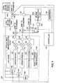
- Fig. 1 illustrates the overall processing steps in an optical fiber manufacturing plant 100.
- processing begins with a laydown process 101 in which a porous preform or soot blank is formed.
- the preform is consolidated in a consolidation process 102.
- the clarified or clear blank is then introduced into a draw furnace 103.
- draw fiber cooling 104 is done as optical fiber is pulled or drawn from the blank. Quality control and packaging 105 follow.
- Large amounts of helium are utilized in a number of processes in a plant such as plant 100.
- Draw fiber cooling 104, draw furnace purging 103, and consclidaticn processing 102 all utilize helium in large enough quantities to make helium recycling both profitable in terms cf cost savings and desirable in terms of better management and utilization of a scarce resource.
- contaminated or spent helium is extracted from each process in the plant 100 utilizing a significant amount of helium.
- helium is shown being recovered from the processes 102-104.
- additional helium utilizing processes may be employed, and it will be understood that helium may be recovered from them as well.
- the recovered helium passes through recovery lines 112, 113 and 114, and valves 122, 123 and 124.
- the nature of the impurities in each of the helium streams may desirably be sensed utilizing sensors 132, 133 and 134 in conjunction with a suitably programmed controller or processor 140.
- the sensors may be infrared ("IR") sensors.
- Gas chromatography may also be utilized. Those of skill in the art will be able to select other suitable sensing mechanisms depending upon their particular application and the available resources.
- Each of the helium streams may be selectively and controllably vented to a system of scrubbers 150 for suitably processing waste gases to meet environmental and safety standards for handling such gas streams.
- This venting may be controlled based on the outputs of the sensors 132-134 which are preferably connected to the controller 140 or a separate controller which will control the appropriate one of the three-way valves 135, 136 or 137.
- the helium streams are then fed on one or more feed lines 151, through one or more controllable valves 153, and one or more compressors 155 to a helium purification plant 160 which may suitably employ one or more purification arrangements.
- exemplary existing purification components and systems include solid and fluid separation systems, cryogenic liquid upgrading systems, chemical adsorption systems, catalytic reaction systems, absorption systems, membrane separation systems and pressure or thermal swing adsorption systems. It is contemplated that further advances in such components and systems will be made, and that one of ordinary skill in the art will be able to select and combine such components to match the purification needed for the impurities of a given stream of helium to be recycled.
- the helium purifier or purification plant 160 removes impurities such as nitrogen, N 2 , oxygen, O 2 , flourine, F 2 , and other flourine containing compounds, chlorine, Cl 2 , hydrochloric acid and other chlorine compounds, HCl, carbon dioxide, CO 2 and the like which may be typical byproducts of the various optical fiber manufacturing processes.
- impurities such as nitrogen, N 2 , oxygen, O 2 , flourine, F 2 , and other flourine containing compounds, chlorine, Cl 2 , hydrochloric acid and other chlorine compounds, HCl, carbon dioxide, CO 2 and the like which may be typical byproducts of the various optical fiber manufacturing processes.
- impurities such as nitrogen, N 2 , oxygen, O 2 , flourine, F 2 , and other flourine containing compounds, chlorine, Cl 2 , hydrochloric acid and other chlorine compounds, HCl, carbon dioxide, CO 2 and the like which may be typical byproducts of the various optical fiber manufacturing processes.
- an integration of the recycling of helium from two or more processes may yield significant advantages over addressing each process separately.
- recovered pure helium is fed through a sensor 161 and a three-way valve 163 to a pure helium holding tank 170 which also receives pure helium make up gas from a source 180 to make up for helium not recovered in recycling.
- Sensor 161 is connected to the controller 140 and is utilized to make a check on the purity of the purified helium. If the helium does meet the process requirement, the helium is rejected and sent to the scrubbers 150 using the three-way valve 163.
- Pure helium is fed from the tank 170 through mass flow controllers (MFCs) 182, 183 and 184 or other flow controllers to the plant 100 to meet the plant's ongoing needs for helium during processing.
- MFCs mass flow controllers
- the suitably programmed controller or processor 140 or a plurality of processors distributed throughout the plant may be utilized to monitor aid control flows, pressures, valves and the like throughout the system. Alternatively, manual adjustments may be made by plant personnel. While a single controller is shown, a plurality of processors or controllers may suitably be employed. Additional valves, pumps, pressure gauges, monitoring instruments and tanks may also be employed depending upon the environment and the application.
- Figs. 2 and 3 illustrate further details of an integrated system and method for providing helium recycling in accordance with the present invention.
- a system in accordance with the present invention may suitably include an optical fiber manufacturing plant 200 employing a consolidation process 202, a draw furnace purging process 203, a draw fiber cooling process 204, and other miscellaneous processes utilizing helium 205.
- Other processes such as laydown, quality control and the like typically will also be employed but are not shown in Fig. 2 as little or no helium is typically used therein.
- the optical fiber plant 200 also preferably includes a first helium purifier 210, a helium impurity sensor 211, a valve 212, a helium storage tank 215, MFCs 216-218 with their own processors for control or controlled by a controller 240, controller 240, a second helium purifier or purification plant 260 for removing impurities, an impurities sensor 261, a three-way valve 262, a second tank 270 for holding pure helium, MFCs 276-278 controlled by the controller 240, and a pure helium makeup source or sources 280.
- Fig. 3 illustrates a method 300 in which in step 301, a first stream of very pure helium, such as "five nines", 99.999%, or alternatively, 99.995% pure helium, is fed from a source of helium such as the tank 270 to a first process in an optical fiber manufacturing plant which requires helium at a first purity level, such as consolidation process 202 in optical fiber plant 200.
- a source of helium such as the tank 270
- impure helium is recovered from the first process and fed to a first purifier, purifier 210.
- step 303 gross impurities such as chlorine and hydrochloric acid are removed, and a second stream of pure helium having a second level purity of for example greater than about 95% is produced.
- this second stream of helium may be tested utilizing a sensor and processor, such as the sensor 211 and controller 240, to confirm that this stream is suitable for usage in other processes such as draw furnace purging 203 or draw fiber cooling 204.
- step 305 if the test. results of step 304 are satisfactory, the helium is collected or stored and cooled, if necessary, utilizing components such as valve 212, a cooling unit or heat exchanger not shown, a compressor net shown, and tank 215.
- this second level of purity helium is fed to one or more processes which requires a lower level of purity of helium.
- the controller 240 and MFCs 216-218 can be utilized to control feeding of helium from the tank 215 to the draw furnace purging process 203, the draw fiber cooling process 204 or the other miscellaneous helium utilizing processes 205.
- step 307 a flow or flows of makeup helium of either 99.995% or less purity are controlled so that adequate helium is provided to processes, such as draw furnace purging 203 and draw fiber cooling 204 which typically utilize more helium than is used in the consolidation process 202.
- waste helium is collected or recovered from one or more processes, such as any of the processes 202-205 and delivered to a second helium purifier, such as the helium purifier or purification plant 260.
- step 309 impurities such as oxygen, O 2 , nitrogen, N 2 , and the like are removed or purged until first level purity, such as 99.995% pure helium results.
- step 310 the purity of the helium from step 309 is tested.
- step 311 where the helium has been tested as pure, the first level purity helium is collected in a tank such as the tanks 270. Finally, in step 312, high purity recycled helium is reutilized in a high purity process, such as the consolidation process 202.
- helium such as 99.995% or sometimes five-nines pure is required for processes such as the consolidation process.
- helium and other gases such as chlorine and oxygen are employed to dry a glass preform formed in the laydown stage.
- Helium containing impurities from the consolidation process including chlorine is a byproduct of the consolidation process.
- Other processes, such as draw furnace purging and draw fiber cooling do not require helium of the same level of purity as consolidation.
- the purifier 210 only serves to remove sufficient impurities, for example, the Cl 2 and HCl byproducts of the consolidation process, such that helium adequately pure for draw purging and draw cooling is produced. This purification is much less expensive then purifying all the recycled helium to 99.995% purity. As previously noted, while the consolidation process may require such very pure helium, the draw process which utilizes helium principally for purging or for heat transfer and cooling may require helium which is only about 95% pure.
- a method and apparatus for helium recycling in connection with the optical fiber manufacturing consolidation process is provided.
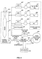
- Fig. 4 illustrates such apparatus 400 in block form.
- consolidation gases such as oxygen, nitrogen, sulfur hexafluoride, SF 6 , chlorine and helium are fed from respective sources 401, 402 and 403 through regulators 404, 405 and 406, and mass flow controllers ("MFCs") 407, 408 and 409. While illustrated in a single block, it will be understood that oxygen, nitrogen, sulfur hexafluoride, as well as other gases, might all be utilized with separate sources.
- a blank or preform 411 to be consolidated is suspended in a known fashion in a consolidation furnace 410.
- the consolidation gases are introduced at the top 412 of the furnace 410.
- spent consolidation gases were simply vented to scrubbing facilities where they were further processed as necessary and then vented to the atmosphere.
- a top seal at the top of the furnace was fairly loose and a slight overpressure of helium was utilized to prevent outside air from entering the system and other gases such as chlorine from exiting the system.
- an improved sealing mechanism 414 to reduce helium loss.
- Spent gases rather than being vented are drawn off through a recovery line 416, a sensor 417, an automatic valve 418 and a compressor 419 to a helium purifier 420.
- the amount of exhaust gas or waste helium out of the consolidation furnace 410 is controlled with the valve 418 based on a measured parameter, such as furnace pressure, exhaust flow, exhaust temperature or exhaust gas composition.
- the measurement of the measured parameter is made by a suitable sensor or sensors, such as the sensor 417. While in the discussion below, sensor 417 is principally discussed as a composition sensor, it will be recognized that pressure, flow and temperature sensors can also be utilized either alone or in connection. It is presently preferred that the exhaust gas flow be controlled based upon furnace pressure as the control loop input for valve 418.
- a second purifier not shown in Fig. 4 may be desirable to employ a second purifier not shown in Fig. 4 to remove chlorine, hydrochloric acid and fluorine compounds before the automatic valve 418 and compressor 419 to reduce corrosion problems in these components.
- the purifier 420 removes contaminants such as chlorine, hydrochloric acid, oxygen, nitrogen, silicon dioxide and any other consolidation process impurities to produce adequately pure helium, such as 99.995%, for recycling to the consolidation process. As discussed above, it is preferable to sense the purity of the recycled helium using a sensor 421 and controllers such as controller 450, and to vent this helium if it is not sufficiently pure using a three-way valve 422 controlled by the controller.
- Pure recycled helium is fed to a pure recycled helium tank 430 and fed from the tank 430 through a recycled helium MFC 440 to join the consolidation gas stream introduced to the furnace 410 at input 412.
- the MFCs 409 and 440 are controlled by the system controller 450 to adjust the mix of helium from the source 403 and tank 430 to reflect helium losses and recycling inefficiencies.
- Scrubbers 460 are provided to process vented gases. While controller 450 is shown in Fig 4. as connected to the MFCs 409 and 440, it will also typically be connected to the sensor 417, the valve 418 and any other process sensors or process control mechanisms, such as valves or MFCs, although those connections are not shown in Fig. 4 to simplify the illustration.
- Fig. 5 illustrates details of one method or process 500 according to the present invention for recycling helium from the consolidation process employed in optical fiber manufacturing.
- a blank such as blank 411 is suspended in a consolidation furnace, such as the furnace 410.
- consolidation gases including pure helium are fed to a consolidation furnace.
- the consolidation gases may be fed by sources 401-403, through regulators 404-406 and MFCs 407-409 to consolidation furnace 410.
- helium is recovered utilizing, by way of example, recovery line 416, sensor and MFC 417, automatic valve 418 and compressor 419.
- the recovered helium may be tested utilizing a sensor and processor, such as the sensor 417 and controller 450.
- the recovered helium may be vented to scrubbers, such as scrubbers 460 utilizing a valve, such as the automatic valve 418, or alternatively, utilizing a valve which may be controlled manually by an operator.
- a valve such as automatic valve 418 may be controlled by the controller 450 or by its own internal processor or controller not shown.
- helium is fed to a helium purifier, such as the helium purifier 420.
- step 508 contaminants such as chlorine, hydrochloric acid, various chlorine compounds, oxygen, nitrogen, silicon dioxide and the like resulting from the consolidation process are removed thereby purifying the helium at the output of the purifier to the same level of purity as the pure source helium provided by a helium source, such as source 403.
- the purity of the helium from step 508 is preferably tested for purity. Utilizing a sensor and controller, such as the sensor 421 and controller 450. If not adequately pure, the helium may be vented to scrubbers, such as the scrubbers 460 utilizing a controllable valve, such as the valve 422.
- step 510 tested pure recycled helium is stored, for example, in a tank such as tank 430.
- step 511 the pure recycled helium is reutilized in the consolidation process.
- the pure recycled helium may be fed from the pure recycled helium tank 430 through MFC 440 and mixed with makeup helium from source 403.
- a controller.or controllers, such as the controller 450 will preferably control the mixing of recycled and fresh helium to make maximum usage of the pure recycled helium.
- An apparatus for recycling helium utilized in the consolidation process of optical fiber manufacturing comprising: a source of pure helium; a delivery mechanism to controllably deliver pure helium from the source to a consolidation furnace; a recovery mechanism for recovering waste helium from the consolidation furnace; a feed apparatus to feed recovered waste helium to a helium purifier; said helium purifier operating to produce an output stream of recycled purified helium satisfactory for reutilization in the consolidation process; a recycle feed apparatus to feed recycled purified helium to the consolidation furnace wherein said recovery mechanism further comprises a sensor for sensing a control loop input parameter selected from the group of measured furnace pressure, waste helium flow, waste helium temperature or waste helium composition.
- the apparatus' recovery mechanism further comprises a valve for controlling the amourt of waste helium from the consolidation furnace based upon the control loop input.
- the apparatus' recovery mechanism further comprises: a sensor for sensing the consolidation furnace pressure as a control loop input; and a controllable valve for controlling the amount of waste helium out of the consolidation furnace based on the control loop input.
- the apparatus further comprises a mixer for mixing recycled purified helium with pure helium from the source of pure helium; and further comprises a process controller to control the mix of recycled purified helium and pure helium.
- the apparatus further comprises a seal for sealing the top of the consolidation furnace.
- the apparatus' feed apparatus further comprises a first sensor for sensing impurities in the recovered waste helium.
- the apparatus further comprises a first sensor to sense the purity of the output stream of recycled purified helium.
- the apparatus further comprises a process controller connected to the first sensor for determining the levels of impurities in the recovered waste helium.
- the feed apparatus further comprises a controllable valve which operates to feed the recovered waste helium either to the helium purifier or to scrubbers and the controller operates to control the controllable valve based upon the determination of the level of impurities in the recovered waste helium.
- the first sensor may comprise: an infrared sensor which outputs a signal having resulting information about the nature of the impurities sensed in the recovered waste helium; or a gas chromatograph.
- the apparatus further comprises a second sensor for sensing the purity of the output stream of recycled purified helium.
- the apparatus further comprises one or more mass flow controllers to control the flow of pure helium, recovered waste helium or purified recycled helium flow; and wherein said one or more flow controllers are controlled by an overall process cont
- a method for recycling helium utilized in optical fiber manufacturing comprising the steps of: collecting waste helium from a plurality of helium utilizing processes; controllably delivering the collected waste helium to a helium purifier which produces an output stream of purified recycled helium and an output stream of impurities; storing the purified recycled helium; and reutilizing the purified recycled helium in optical fiber manufacturing and further comprising the step of testing the levels of impurities in the collected waste helium; and further comprising the step of controllably mixing pure helium from a pure helium source with the recycled purified helium before reutilizing the purified recycled helium in optical fiber manufacturing; and further comprising the step of controlling the flow of the purified recycled helium reutilized in optical fiber manufacturing.
- a method for recycling helium utilized in optical fiber manufacturing comprising the steps of: feeding a first stream of helium of a first level of purity to a first optical fiber manufacturing process; recovering waste helium with impurities from the first process; feeding the recovered waste helium to a first purifier; removing impurities utilizing the first purifier and producing a second stream of helium of a second level of purity; feeding the second stream of helium to a second optical fiber manufacturing process and wherein the first optical manufacturing process is consolidation; and wherein the first level of purity is at least 99.995% pure; and also wherein the recovered waste helium includes chlorine impurities and the purifier is operable to efficiently remove said chlorine impurities.
- the method further comprises the step of testing the impurities of the recovered waste helium.
- the method further comprises the step of testing the impurities of the second stream of helium.
- the method further comprises the step of collecting and storing the second stream of helium before feeding the second stream of helium to a second optical fiber manufacturing process.
- the second optical manufacturing process can be either draw furnace purging or draw fiber cooling.
- the method further comprises the step of controllably feeding makeup helium to the second optical fiber manufacturing process to insure an adequate supply of helium to the second optical fiber manufacturing process.
- said second level of purity is less than said first level of purity.
- With the method said second level of purity is at least 95% pure.
- the method comprises the further step of: collecting additional waste helium from any helium utilizing process utilized in optical fiber manufacturing; feeding said additional waste helium to a second purifier; and removing impurities utilizing the second purifier to produce a third stream of helium of the first level of purity.
- An apparatus for recycling helium utilized in optical fiber manufacturing comprising: a source of a first stream of helium of a first level of purity; a feed mechanism to feed said first stream to a first optical fiber manufacturing process; a recovery mechanism for recovering waste helium with impurities from the first process; a second feed mechanism for feeding the recovered waste helium to a first helium purifier; the first helium purifier producing a second stream of helium of a second level of purity; a third feed mechanism to feed the second stream of helium to a second optical fiber manufacturing process, wherein the first optical fiber manufacturing process is a consolidation process and the apparatus further comprises a consolidation furnace fitted with a seal to reduce helium losses, wherein the second optical fiber manufacturing process is either draw furnace purging or draw fiber cooling, and wherein the first level of purity is at least 99.995% pure; and also wherein the second level of purity is at least 95% pure but less than 99.995% pure; and further wherein the first purifier includes a chlorine purification apparatus to remove chlorine impur
Landscapes
- Chemical & Material Sciences (AREA)
- Engineering & Computer Science (AREA)
- Organic Chemistry (AREA)
- Materials Engineering (AREA)
- Life Sciences & Earth Sciences (AREA)
- General Life Sciences & Earth Sciences (AREA)
- Geochemistry & Mineralogy (AREA)
- Manufacturing & Machinery (AREA)
- General Chemical & Material Sciences (AREA)
- Chemical Kinetics & Catalysis (AREA)
- Physics & Mathematics (AREA)
- Thermal Sciences (AREA)
- Analytical Chemistry (AREA)
- Inorganic Chemistry (AREA)
- Mechanical Engineering (AREA)
- General Engineering & Computer Science (AREA)
- Oil, Petroleum & Natural Gas (AREA)
- Separation By Low-Temperature Treatments (AREA)
- Manufacture, Treatment Of Glass Fibers (AREA)
- Organic Low-Molecular-Weight Compounds And Preparation Thereof (AREA)
Applications Claiming Priority (3)
| Application Number | Priority Date | Filing Date | Title |
|---|---|---|---|
| US2079696P | 1996-06-24 | 1996-06-24 | |
| US20796P | 1996-06-24 | ||
| PCT/US1997/009968 WO1997049960A1 (en) | 1996-06-24 | 1997-06-09 | Helium recycling for optical fiber manufacturing |
Publications (3)
| Publication Number | Publication Date |
|---|---|
| EP0879389A1 EP0879389A1 (en) | 1998-11-25 |
| EP0879389A4 EP0879389A4 (2) | 1998-12-02 |
| EP0879389B1 true EP0879389B1 (en) | 2003-05-21 |
Family
ID=21800625
Family Applications (1)
| Application Number | Title | Priority Date | Filing Date |
|---|---|---|---|
| EP97929877A Expired - Lifetime EP0879389B1 (en) | 1996-06-24 | 1997-06-09 | Helium recycling for optical fiber manufacturing |
Country Status (12)
| Country | Link |
|---|---|
| US (3) | US5890376C1 (2) |
| EP (1) | EP0879389B1 (2) |
| JP (1) | JPH11513011A (2) |
| KR (1) | KR19990044095A (2) |
| CN (1) | CN1196789A (2) |
| AT (1) | ATE241119T1 (2) |
| AU (1) | AU714363B2 (2) |
| BR (1) | BR9702330A (2) |
| CA (1) | CA2221691A1 (2) |
| DE (1) | DE69722180D1 (2) |
| DK (1) | DK0879389T3 (2) |
| WO (1) | WO1997049960A1 (2) |
Families Citing this family (36)
| Publication number | Priority date | Publication date | Assignee | Title |
|---|---|---|---|---|
| JP2001163632A (ja) * | 1999-12-13 | 2001-06-19 | Sumitomo Electric Ind Ltd | 光ファイバ製造方法および光ファイバ製造装置 |
| AU7185900A (en) * | 2000-01-14 | 2001-07-19 | Boc Group, Inc., The | Helium recovery process |
| US6345451B1 (en) * | 2000-03-23 | 2002-02-12 | Air Products And Chemicals, Inc. | Method and apparatus for hot continuous fiber cooling with cooling gas recirculation |
| FR2808793B1 (fr) * | 2000-05-15 | 2002-09-27 | Air Liquide | Fabrication de fibre optique refroidie a l'helium avec recyclage sans purification de l'helium |
| FR2815399B1 (fr) * | 2000-10-18 | 2003-01-03 | Air Liquide | Procede et installation de purification et recyclage de l'helium, et leur application a la fabrication de fibres optiques |
| US20020134530A1 (en) * | 2001-03-20 | 2002-09-26 | American Air Liquide, Inc. | Heat transfer fluids and methods of making and using same |
| US20020129622A1 (en) * | 2001-03-15 | 2002-09-19 | American Air Liquide, Inc. | Heat transfer fluids and methods of making and using same |
| US6668582B2 (en) | 2001-04-20 | 2003-12-30 | American Air Liquide | Apparatus and methods for low pressure cryogenic cooling |
| US6651358B2 (en) | 2001-04-30 | 2003-11-25 | American Air Liquide, Inc. | Heat transfer fluids and methods of making and using same comprising hydrogen, helium and combinations thereof |
| US6574972B2 (en) | 2001-04-30 | 2003-06-10 | L'air Liquide - Societe' Anonyme A' Directoire Et Conseil De Surveillance Pour L'etude Et L'exploitation Des Procedes Georges Claude | Low temperature heat transfer methods |
| US6789400B2 (en) * | 2001-11-30 | 2004-09-14 | The Boc Group, Inc. | Cap assembly and optical fiber cooling process |
| FR2833188B1 (fr) * | 2001-12-06 | 2004-05-21 | Air Liquide | Installation et procede de production de produits en utilisant un fluide |
| US6701728B1 (en) | 2002-08-28 | 2004-03-09 | The Boc Group, Inc. | Apparatus and method for recovery and recycle of optical fiber coolant gas |
| US20040139766A1 (en) * | 2003-01-17 | 2004-07-22 | Weeks Gene K. | Systems and methods for recycling gas used in treating optical fiber |
| US20040194513A1 (en) * | 2003-04-04 | 2004-10-07 | Giacobbe Frederick W | Fiber coolant system including improved gas seals |
| JP2004359520A (ja) * | 2003-06-06 | 2004-12-24 | Toshiba Ceramics Co Ltd | 合成シリカガラスの製造方法及びその製造装置 |
| US7261763B2 (en) * | 2003-07-17 | 2007-08-28 | The Boc Group, Inc. | Method for the recovery and recycle of helium and chlorine |
| US20050011230A1 (en) * | 2003-07-17 | 2005-01-20 | Shirley Arthur I. | Method for blending and recirculating deuterium-containing gas |
| US7984838B2 (en) * | 2006-05-04 | 2011-07-26 | Medtronic Ps Medical, Inc. | Recycled helium gas surgical instrument |
| US20090324816A1 (en) * | 2008-06-27 | 2009-12-31 | Paul Andrew Chludzinski | Low Permeability Gas Recycling in Consolidation |
| NL2002422C2 (en) * | 2009-01-16 | 2010-07-19 | Draka Comteq Bv | Method and system to manufacture an optical fibre preform. |
| JP5323530B2 (ja) * | 2009-02-23 | 2013-10-23 | 古河電気工業株式会社 | 光ファイバの製造方法 |
| US8444749B2 (en) | 2009-06-10 | 2013-05-21 | L'air Liquide, Societe Anonyme Pour L'etude Et L'exploitation Des Procedes Georges Claude | Method and system for membrane-based gas recovery |
| CN103363294B (zh) * | 2013-07-08 | 2016-02-03 | 安徽万瑞冷电科技有限公司 | 一种用于空调行业的废氦气回收系统 |
| US9649590B2 (en) * | 2014-01-13 | 2017-05-16 | Versum Materials Us, Llc | System and method for gas recovery and reuse |
| US10308544B2 (en) | 2015-10-13 | 2019-06-04 | Corning Incorporated | Gas reclamation system for optical fiber production |
| CN106744749A (zh) * | 2016-11-30 | 2017-05-31 | 富通集团(嘉善)通信技术有限公司 | 用于光纤拉丝系统的氦气在线回收利用方法及装置 |
| CN109896738B (zh) * | 2017-02-28 | 2021-08-06 | 天津富通集团有限公司 | 光纤预制棒的生产工艺 |
| US11136256B2 (en) * | 2017-07-25 | 2021-10-05 | Made In Space, Inc. | System and method for manufacturing optical fiber |
| CN108328919A (zh) * | 2018-04-19 | 2018-07-27 | 合肥硕朗自动化科技有限公司 | 一种光纤拉丝冷却管氦气回收装置 |
| CN109930201A (zh) * | 2019-03-08 | 2019-06-25 | 银川隆基硅材料有限公司 | 一种气体回用控制方法及气体回用控制设备 |
| CN110498401B (zh) * | 2019-09-02 | 2024-05-17 | 北京中科富海低温科技有限公司 | 氦气回收净化装置 |
| CN112225448B (zh) * | 2020-10-22 | 2022-12-06 | 江苏亨通光导新材料有限公司 | 一种用于光纤预制棒烧结的氦氯混合气循环系统 |
| CN112604465A (zh) * | 2020-11-03 | 2021-04-06 | 国网湖北省电力有限公司检修公司 | 用于六氟化硫气体放电降解处理的气体循环装置及方法 |
| EP4080146A1 (en) * | 2021-04-21 | 2022-10-26 | Linde GmbH | Method of operating a fabrication plant and fabrication plant |
| EP4265322A1 (en) * | 2022-04-22 | 2023-10-25 | L'air Liquide, Societe Anonyme Pour L'etude Et L'exploitation Des Procedes Georges Claude | Helium recovery process |
Family Cites Families (17)
| Publication number | Priority date | Publication date | Assignee | Title |
|---|---|---|---|---|
| US3181307A (en) * | 1960-02-16 | 1965-05-04 | Phillips Petroleum Co | Helium separation |
| US3194054A (en) * | 1961-08-07 | 1965-07-13 | William M Deaton | Apparatus for concentrating trace impurities in high-purity helium |
| US3333435A (en) * | 1964-08-28 | 1967-08-01 | Phillips Petroleum Co | Process and apparatus for handling off-specification helium |
| US3792591A (en) * | 1970-03-24 | 1974-02-19 | Cryogenic Technology Inc | Helium purification method and apparatus |
| JPS56109831A (en) * | 1980-01-30 | 1981-08-31 | Nippon Telegr & Teleph Corp <Ntt> | Manufacture of base material for optical fiber |
| FR2510539A1 (fr) * | 1981-07-28 | 1983-02-04 | Expertises Sa Cie Maritime | Procede et installation d'epuration de l'helium contenu dans un melange de gaz |
| JPS60103006A (ja) * | 1983-11-09 | 1985-06-07 | Toyo Sanso Kk | 可搬型ヘリウム回収精製装置 |
| JPS60122741A (ja) * | 1983-12-08 | 1985-07-01 | Hitachi Cable Ltd | 光ファイバ母材の製造法 |
| JPS61261223A (ja) * | 1985-05-13 | 1986-11-19 | Furukawa Electric Co Ltd:The | 多孔質ガラス母材用透明ガラス化炉 |
| US4863501A (en) * | 1985-09-26 | 1989-09-05 | Polaroid Corporation, Patent Department | Method of employing plasma for finishing start rods |
| JPS62153132A (ja) * | 1985-12-26 | 1987-07-08 | Furukawa Electric Co Ltd:The | ガラス処理炉におけるガス循環装置 |
| US4659351A (en) * | 1986-01-29 | 1987-04-21 | Air Products And Chemicals, Inc. | Combined process to produce liquid helium, liquid nitrogen, and gaseous nitrogen from a crude helium feed |
| EP0462893B1 (en) * | 1990-06-19 | 1995-04-12 | Fujikura Ltd. | Method for splicing and reinforcing carbon coated optical fibers |
| JPH04240129A (ja) * | 1991-01-18 | 1992-08-27 | Sumitomo Electric Ind Ltd | 光ファイバの製造方法及び装置 |
| US5377491A (en) * | 1992-12-11 | 1995-01-03 | Praxair Technology, Inc. | Coolant recovery process |
| JPH09142892A (ja) * | 1995-11-28 | 1997-06-03 | Furukawa Electric Co Ltd:The | 被覆光ファイバの製造装置及び製造方法 |
| ID17537A (id) * | 1996-07-26 | 1998-01-08 | Praxair Technology Inc | Perolehan kembali helium bagi manupaktur serat optis |
-
1997
- 1997-06-09 JP JP10503085A patent/JPH11513011A/ja active Pending
- 1997-06-09 BR BR9702330A patent/BR9702330A/pt not_active Application Discontinuation
- 1997-06-09 AU AU33835/97A patent/AU714363B2/en not_active Ceased
- 1997-06-09 EP EP97929877A patent/EP0879389B1/en not_active Expired - Lifetime
- 1997-06-09 CA CA002221691A patent/CA2221691A1/en not_active Abandoned
- 1997-06-09 WO PCT/US1997/009968 patent/WO1997049960A1/en not_active Ceased
- 1997-06-09 CN CN97190756A patent/CN1196789A/zh active Pending
- 1997-06-09 DK DK97929877T patent/DK0879389T3/da active
- 1997-06-09 KR KR1019980701328A patent/KR19990044095A/ko not_active Ceased
- 1997-06-09 AT AT97929877T patent/ATE241119T1/de not_active IP Right Cessation
- 1997-06-09 DE DE69722180T patent/DE69722180D1/de not_active Expired - Lifetime
- 1997-12-11 US US08981525 patent/US5890376C1/en not_active Expired - Fee Related
-
1999
- 1999-03-30 US US09/281,555 patent/US6092391A/en not_active Expired - Fee Related
-
2000
- 2000-07-05 US US09/610,038 patent/US6253575B1/en not_active Expired - Fee Related
Also Published As
| Publication number | Publication date |
|---|---|
| CA2221691A1 (en) | 1997-12-24 |
| AU3383597A (en) | 1998-01-14 |
| JPH11513011A (ja) | 1999-11-09 |
| US5890376C1 (en) | 2001-05-15 |
| US6092391A (en) | 2000-07-25 |
| EP0879389A4 (2) | 1998-12-02 |
| WO1997049960A1 (en) | 1997-12-31 |
| ATE241119T1 (de) | 2003-06-15 |
| DK0879389T3 (da) | 2003-09-15 |
| CN1196789A (zh) | 1998-10-21 |
| US5890376A (en) | 1999-04-06 |
| US6253575B1 (en) | 2001-07-03 |
| EP0879389A1 (en) | 1998-11-25 |
| KR19990044095A (ko) | 1999-06-25 |
| BR9702330A (pt) | 1999-07-20 |
| AU714363B2 (en) | 1999-12-23 |
| DE69722180D1 (de) | 2003-06-26 |
Similar Documents
| Publication | Publication Date | Title |
|---|---|---|
| EP0879389B1 (en) | Helium recycling for optical fiber manufacturing | |
| EP0601601B1 (en) | Coolant recovery system | |
| EP0820963B1 (en) | Method for recovering helium from an optical fibre manufacturing process | |
| US20100313750A1 (en) | Method and System for Membrane-Based Gas Recovery | |
| US20110168674A1 (en) | Plasma processing method and apparatus | |
| JP2000072469A (ja) | 熱間絞り成形したファイバを冷却する方法 | |
| US6701728B1 (en) | Apparatus and method for recovery and recycle of optical fiber coolant gas | |
| US6345451B1 (en) | Method and apparatus for hot continuous fiber cooling with cooling gas recirculation | |
| MXPA98001468A (en) | Recirculation of helium for the fiber opt manufacture | |
| EP1498398A2 (en) | Method for blending and recirculating deuterium-containing gas | |
| EP0924169A2 (en) | Air separation float glass system | |
| US6648946B2 (en) | Process for recovering helium using an eductor | |
| JPS62153132A (ja) | ガラス処理炉におけるガス循環装置 | |
| MXPA97005681A (en) | Recovery of helium for the fiber opt manufacture | |
| RU98104472A (ru) | Рециклизация гелия для получения оптического волокна | |
| MXPA05005629A (es) | Suministro de gas y recuperacion para atomizador de metal. | |
| CN119971932A (zh) | 一种Unipol聚丙烯反应器组分控制方法 | |
| JPH1163813A (ja) | アルゴンの回収方法および同装置 | |
| JPH05256570A (ja) | Arガスの回収方法 | |
| TF | Cryogenic storage vessels |
Legal Events
| Date | Code | Title | Description |
|---|---|---|---|
| PUAI | Public reference made under article 153(3) epc to a published international application that has entered the european phase |
Free format text: ORIGINAL CODE: 0009012 |
|
| 17P | Request for examination filed |
Effective date: 19980128 |
|
| AK | Designated contracting states |
Kind code of ref document: A1 Designated state(s): AT CH DE DK ES FR GB IT LI NL SE |
|
| A4 | Supplementary search report drawn up and despatched |
Effective date: 19981019 |
|
| AK | Designated contracting states |
Kind code of ref document: A4 Designated state(s): AT CH DE DK ES FR GB IT LI NL SE |
|
| 17Q | First examination report despatched |
Effective date: 20000901 |
|
| GRAH | Despatch of communication of intention to grant a patent |
Free format text: ORIGINAL CODE: EPIDOS IGRA |
|
| GRAH | Despatch of communication of intention to grant a patent |
Free format text: ORIGINAL CODE: EPIDOS IGRA |
|
| GRAA | (expected) grant |
Free format text: ORIGINAL CODE: 0009210 |
|
| AK | Designated contracting states |
Designated state(s): AT CH DE DK ES FR GB IT LI NL SE |
|
| PG25 | Lapsed in a contracting state [announced via postgrant information from national office to epo] |
Ref country code: LI Free format text: LAPSE BECAUSE OF FAILURE TO SUBMIT A TRANSLATION OF THE DESCRIPTION OR TO PAY THE FEE WITHIN THE PRESCRIBED TIME-LIMIT Effective date: 20030521 Ref country code: CH Free format text: LAPSE BECAUSE OF FAILURE TO SUBMIT A TRANSLATION OF THE DESCRIPTION OR TO PAY THE FEE WITHIN THE PRESCRIBED TIME-LIMIT Effective date: 20030521 Ref country code: AT Free format text: LAPSE BECAUSE OF FAILURE TO SUBMIT A TRANSLATION OF THE DESCRIPTION OR TO PAY THE FEE WITHIN THE PRESCRIBED TIME-LIMIT Effective date: 20030521 |
|
| REG | Reference to a national code |
Ref country code: GB Ref legal event code: FG4D |
|
| PGFP | Annual fee paid to national office [announced via postgrant information from national office to epo] |
Ref country code: FR Payment date: 20030523 Year of fee payment: 7 |
|
| PGFP | Annual fee paid to national office [announced via postgrant information from national office to epo] |
Ref country code: NL Payment date: 20030528 Year of fee payment: 7 |
|
| PGFP | Annual fee paid to national office [announced via postgrant information from national office to epo] |
Ref country code: GB Payment date: 20030529 Year of fee payment: 7 |
|
| REG | Reference to a national code |
Ref country code: CH Ref legal event code: EP |
|
| PGFP | Annual fee paid to national office [announced via postgrant information from national office to epo] |
Ref country code: DK Payment date: 20030610 Year of fee payment: 7 |
|
| REF | Corresponds to: |
Ref document number: 69722180 Country of ref document: DE Date of ref document: 20030626 Kind code of ref document: P |
|
| PG25 | Lapsed in a contracting state [announced via postgrant information from national office to epo] |
Ref country code: SE Free format text: LAPSE BECAUSE OF FAILURE TO SUBMIT A TRANSLATION OF THE DESCRIPTION OR TO PAY THE FEE WITHIN THE PRESCRIBED TIME-LIMIT Effective date: 20030821 |
|
| PG25 | Lapsed in a contracting state [announced via postgrant information from national office to epo] |
Ref country code: DE Free format text: LAPSE BECAUSE OF FAILURE TO SUBMIT A TRANSLATION OF THE DESCRIPTION OR TO PAY THE FEE WITHIN THE PRESCRIBED TIME-LIMIT Effective date: 20030822 |
|
| PG25 | Lapsed in a contracting state [announced via postgrant information from national office to epo] |
Ref country code: ES Free format text: LAPSE BECAUSE OF FAILURE TO SUBMIT A TRANSLATION OF THE DESCRIPTION OR TO PAY THE FEE WITHIN THE PRESCRIBED TIME-LIMIT Effective date: 20030901 |
|
| REG | Reference to a national code |
Ref country code: DK Ref legal event code: T3 |
|
| REG | Reference to a national code |
Ref country code: CH Ref legal event code: PL |
|
| ET | Fr: translation filed | ||
| PLBE | No opposition filed within time limit |
Free format text: ORIGINAL CODE: 0009261 |
|
| STAA | Information on the status of an ep patent application or granted ep patent |
Free format text: STATUS: NO OPPOSITION FILED WITHIN TIME LIMIT |
|
| 26N | No opposition filed |
Effective date: 20040224 |
|
| PG25 | Lapsed in a contracting state [announced via postgrant information from national office to epo] |
Ref country code: GB Free format text: LAPSE BECAUSE OF NON-PAYMENT OF DUE FEES Effective date: 20040609 |
|
| PG25 | Lapsed in a contracting state [announced via postgrant information from national office to epo] |
Ref country code: DK Free format text: LAPSE BECAUSE OF NON-PAYMENT OF DUE FEES Effective date: 20040630 |
|
| PG25 | Lapsed in a contracting state [announced via postgrant information from national office to epo] |
Ref country code: NL Free format text: LAPSE BECAUSE OF NON-PAYMENT OF DUE FEES Effective date: 20050101 |
|
| GBPC | Gb: european patent ceased through non-payment of renewal fee |
Effective date: 20040609 |
|
| REG | Reference to a national code |
Ref country code: DK Ref legal event code: EBP |
|
| PG25 | Lapsed in a contracting state [announced via postgrant information from national office to epo] |
Ref country code: FR Free format text: LAPSE BECAUSE OF NON-PAYMENT OF DUE FEES Effective date: 20050228 |
|
| NLV4 | Nl: lapsed or anulled due to non-payment of the annual fee |
Effective date: 20050101 |
|
| REG | Reference to a national code |
Ref country code: FR Ref legal event code: ST |
|
| PG25 | Lapsed in a contracting state [announced via postgrant information from national office to epo] |
Ref country code: IT Free format text: LAPSE BECAUSE OF NON-PAYMENT OF DUE FEES Effective date: 20050609 |