EP0878617B1 - Verfahren zur Bestimmung der Öffnungszeit eines Einspritzventiles eines Common-Rail-Einspritzsystemes - Google Patents
Verfahren zur Bestimmung der Öffnungszeit eines Einspritzventiles eines Common-Rail-Einspritzsystemes Download PDFInfo
- Publication number
- EP0878617B1 EP0878617B1 EP98107920A EP98107920A EP0878617B1 EP 0878617 B1 EP0878617 B1 EP 0878617B1 EP 98107920 A EP98107920 A EP 98107920A EP 98107920 A EP98107920 A EP 98107920A EP 0878617 B1 EP0878617 B1 EP 0878617B1
- Authority
- EP
- European Patent Office
- Prior art keywords
- fuel
- pressure
- injection
- accordance
- determined
- Prior art date
- Legal status (The legal status is an assumption and is not a legal conclusion. Google has not performed a legal analysis and makes no representation as to the accuracy of the status listed.)
- Expired - Lifetime
Links
Images


Classifications
-
- F—MECHANICAL ENGINEERING; LIGHTING; HEATING; WEAPONS; BLASTING
- F02—COMBUSTION ENGINES; HOT-GAS OR COMBUSTION-PRODUCT ENGINE PLANTS
- F02D—CONTROLLING COMBUSTION ENGINES
- F02D41/00—Electrical control of supply of combustible mixture or its constituents
- F02D41/30—Controlling fuel injection
- F02D41/38—Controlling fuel injection of the high pressure type
- F02D41/40—Controlling fuel injection of the high pressure type with means for controlling injection timing or duration
- F02D41/402—Multiple injections
- F02D41/403—Multiple injections with pilot injections
-
- F—MECHANICAL ENGINEERING; LIGHTING; HEATING; WEAPONS; BLASTING
- F02—COMBUSTION ENGINES; HOT-GAS OR COMBUSTION-PRODUCT ENGINE PLANTS
- F02D—CONTROLLING COMBUSTION ENGINES
- F02D41/00—Electrical control of supply of combustible mixture or its constituents
- F02D41/30—Controlling fuel injection
- F02D41/38—Controlling fuel injection of the high pressure type
- F02D41/3809—Common rail control systems
-
- F—MECHANICAL ENGINEERING; LIGHTING; HEATING; WEAPONS; BLASTING
- F02—COMBUSTION ENGINES; HOT-GAS OR COMBUSTION-PRODUCT ENGINE PLANTS
- F02D—CONTROLLING COMBUSTION ENGINES
- F02D2250/00—Engine control related to specific problems or objectives
- F02D2250/04—Fuel pressure pulsation in common rails
-
- Y—GENERAL TAGGING OF NEW TECHNOLOGICAL DEVELOPMENTS; GENERAL TAGGING OF CROSS-SECTIONAL TECHNOLOGIES SPANNING OVER SEVERAL SECTIONS OF THE IPC; TECHNICAL SUBJECTS COVERED BY FORMER USPC CROSS-REFERENCE ART COLLECTIONS [XRACs] AND DIGESTS
- Y02—TECHNOLOGIES OR APPLICATIONS FOR MITIGATION OR ADAPTATION AGAINST CLIMATE CHANGE
- Y02T—CLIMATE CHANGE MITIGATION TECHNOLOGIES RELATED TO TRANSPORTATION
- Y02T10/00—Road transport of goods or passengers
- Y02T10/10—Internal combustion engine [ICE] based vehicles
- Y02T10/40—Engine management systems
Definitions
- the present invention relates to a method for determining the opening time of a Injection valves of a common rail injection system, in which a map from the amount of fuel to be injected and the static pressure in the common rail a Injection duration is derived.
- the Opening period of the injection valve is better adapted to the variable pressure.
- the Vibration of the pressure causes it to first drop and then rise. This Increase oscillates even over the value of the static pressure in the common rail system out.
- the opening time of the injection valve with respect to the opening time at a static pressure must be shortened or extended in the common rail system, ie the current temporal value of the pressure can be determined.
- the time course of the pressure oscillations shows in particular, that it due to the reduction in the amount of fuel in the common rail initially comes to a drop in pressure. So if the next injection process temporally so close to the preceding injection process that the pressure oscillation not already again exceeded the value of the static pressure in the common rail, so the opening period of the injection valve must be extended.
- the pressure oscillation can be modeled as a single frequency oscillation represent. Practice shows, however, that the oscillation as a superposition of several Represents vibrations with different frequencies. The time behavior of the vibration is therefore stored as a function of the compressibility in a map.
- the at least one size is the compressibility represents the speed of sound of the fuel, the elasitic modulus of the Fuel and / or the density of the fuel.
- the at least one size is determined by the static Rail pressure and / or the fuel temperature determined.
- the at least one preceding Injection process injected amount of fuel from the driving time of the valve in the derived at least one previous injection process.
- the amount of fuel is easily determinable from already available data.
- the amplitude or the factor based on at least a size that represents the compressibility of the fuel.
- the at least one quantity is the speed of sound of the fuel, the Elasitizticiansmodul of the fuel and / or the density of the fuel.
- a value of the pressure is determined from the amplitude and the phase position or the normalized value of the pressure deviation and the factor. This Value of the pressure is added to the rail pressure to a sum pressure.
- the opening hours of the injection valve is determined from the map, with this total pressure as Common rail pressure and the requested fuel quantity form the input variables.
- Figure 1 shows an embodiment of the method according to the invention, which as Programming a microprocessor can be realized.
- the inventive method is then passed before each injection to a corrected opening time and to obtain a corrected drive duration of the injection valve.
- a quantity is determined which determines the compressibility of the Represents fuel.
- This size can, for example, the speed of sound in the Fuel the modulus of elasticity of the fuel, the density of the fuel or a Be combination of these sizes.
- the size is dependent on the pressure in the common rail system and the fuel temperature determined. These two variables affect the Compressibility of the fuel, so that their consideration proved to be advantageous Has.
- step 102 the determined quantity becomes the time behavior of the pressure oscillation certainly.
- This time behavior of the pressure oscillation relates to a representation of the Time course with a normalized amplitude. The due to the existing conditions actually resulting amplitude is taken into account in subsequent process steps.
- the time behavior can be modeled as a sinusoidal oscillation with a negative sign are shown, which begins at the beginning of an injection process.
- the duration of the Sinusoidal be determined. For example, the amount of time over the size in a characteristic curve, with a sufficient number of nodes is stored.
- step 103 the time difference then becomes the beginning of the last injection process and the determined period of time, the phase position of the pressure oscillation at the current time determined.
- the pressure oscillation will be a superposition of several vibrations represent with different frequencies.
- the normalized course of this pressure oscillation is in a three-dimensional map depending on the specific size stored.
- a normalized value of the pressure deviation can then be based on the time since the beginning the last injection process and the specific size read from the map become.
- An embodiment of such a map is shown in FIG. 2, in which the normalized amplitude A_norm, the specific size B and the time .DELTA.t span three-dimensional characteristic map. This map can with as many nodes be stored so that an evaluation with a sufficient accuracy possible is.
- the reading of the normalized pressure deviation from the characteristic field corresponds in this case the steps 102 and 103.
- a variable is again determined which determines the compressibility of the Represents fuel.
- This size can, for example, the speed of sound in the Fuel, the modulus of elasticity of the fuel, the density of the fuel or a Be combination of these sizes.
- the size determined in step 104 may be the same size as in step 101.
- the compressibility not only has an influence on the time behavior the vibration but also the amplitude.
- this size will turn into Dependence on the pressure in the common rail system and / or the temperature determined.
- step 105 an amplitude or a factor is determined for the size with which the normalized value of the pressure deviation is multiplied.
- the amplitude or the factor can be plotted in a map over the particular size.
- the size of the amplitude or the factor is still based on the last Injection process determined amount of fuel determined.
- This amount of fuel determines essentially the amplitude or the factor.
- the amount of fuel can, for example, due the opening duration of the injection valve are derived in the last injection process. It is also possible to determine the value of the last injection process To take amount of fuel as the amount of fuel that in the last injection process was injected.
- step 106 from the amplitude and the phase angle based on the course of the Sine wave determines the value of the pressure that is related to the static system pressure in the Common rail system is added. If the pressure oscillation from an overlay of several frequencies and therefore in steps 102 and 103 a normalized value the pressure deviation was determined from a map, this normalized value of Pressure deviation multiplied by the factor multiplied by the factor corresponding to step 106 of the pressure added to the static pressure in the common rail system.
- FIG. 2 shows a representation of a standardized pressure oscillation in dependence on the Compressibility of the fuel descriptive size B and the time difference .DELTA.t since the beginning the last injection process.
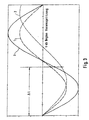
- FIG. 3 shows by way of example the determination of the value of the pressure by which the pressure in FIG Common rail system is corrected.
- the duration of the pressure oscillation is determined. Exemplary here are two different normalized pressure vibrations 1 and 2 shown.
- the pressure oscillation 1 has the determined time duration.
- the amplitude of the Pressure oscillation takes into account or a factor with which the normalized value of the Pressure oscillation is multiplied.
- the illustrated pressure oscillation 3 corresponds to the Pressure oscillation 1 considering the amplitude or the factor.
- the corresponding Value on the curve 3 is thus the value of the pressure to the pressure in the common rail system must be corrected.
Landscapes
- Engineering & Computer Science (AREA)
- Chemical & Material Sciences (AREA)
- Combustion & Propulsion (AREA)
- Mechanical Engineering (AREA)
- General Engineering & Computer Science (AREA)
- Electrical Control Of Air Or Fuel Supplied To Internal-Combustion Engine (AREA)
- Fuel-Injection Apparatus (AREA)
- Developing Agents For Electrophotography (AREA)
Description
- Fig. 1:
- ein Ausführungsbeispiel eines Verfahrens zur Bestimmung eines korrigierten Wert des Druckes,
- Fig. 2:
- eine Darstellung eines Kennfeldes, aus dem ein normierter Wert einer Druckabweichung entnommen werden kann.
Claims (10)
- Verfahren zur Bestimmung der Öffnungszeit eines Einspritzventiles eines Common-Rail-Einspritzsystemes, bei dem aus einem Kennfeld anhand der einzuspritzenden Kraftstoffmenge und des statischen Druckes im Common-Rail eine Einspritzdauer abgeleitet wird,
dadurch gekennzeichnet, daß für die Ablesung im Kennfeld der Wert des statischen Druckes im Common-Rail um einen bestimmten Betrag korrigiert wird (106), der sichsowohl aus dem Schwingungsverhalten des Kraftstoffes in Abhängigkeit von dessen Kompressibilität,als auch aus der entnommenen Kraftstoffmenge oder der Ansteuerdauer des Einspritzventils bei wenigstens einem vorausgehenden Einspritzvorgang,als auch der Zeit zwischen dem wenigstens einen vorausgehenden Einspritzvorgang und dem aktuellen Einspritzvorgang ergibt. - Verfahren nach Anspruch 1,
dadurch gekennzeichnet, daß das Zeitverhalten einer Druckschwingung anhand wenigstens einer Größe bestimmt wird, die die Kompressibilität des Kraftstoffes repräsentiert (101). - Verfahren nach Anspruch 2,
dadurch gekennzeichnet, daß die wenigstens eine Größe die Schallgeschwindigkeit des Kraftstoffes, das Elasitizitätsmodul des Kraftstoffes und/oder die Dichte des Kraftstoffes ist (101). - Verfahren nach Anspruch 2 oder 3,
dadurch gekennzeichnet, daß die wenigstens eine Größe anhand des statischen Raildruckes und/oder der Kraftfstofftemperatur bestimmt wird (101). - Verfahren nach einem der Ansprüche 2 bis 4,
dadurch gekennzeichnet, daß aus der Zeitdauer zwischen dem wenigstens einen vorausgegangenen Einspritzvorgang und dem durchzuführenden Einspritzvorgang die Phasenlage bzw. ein normierter Wert der Druckabweichung zum Zeitpunkt des Beginns des durchzuführenden Einspritzvorganges bestimmt wird (103). - Verfahren nach einem der Ansprüche 1 bis 5,
dadurch gekennzeichnet, daß aus der bei dem wenigstens einen vorhergehenden Einspritzvorgang eingespritzten Kraftstoffmenge oder der Ansteuerdauer des Einspritzventils die Amplitude der Druckschwingung abgeleitet wird bzw. ein Faktor, mit dem der normierte Wert der Druckabweichung multipliziert wird (105). - Verfahren nach Anspruch 6,
dadurch gekennzeichnet, daß die bei dem wenigstens einen vorhergehenden Einspritzvorgang eingespritzte Kraftstoffmenge aus der Ansteuerdauer des Ventiles bei dem wenigstens einen vorhergehenden Einspritzvorgang abgeleitet wird (105). - Verfahren nach Anspruch 6 oder 7,
dadurch gekennzeichnet, daß die Amplitude bzw. der Faktor anhand wenigstens einer Größe bestimmt wird, die die Kompressibilität des Kraftstoffes repräsentiert (104). - Verfahren nach Anspruch 8,
dadurch gekennzeichnet, daß die wenigstens eine Größe die Schallgeschwindigkeit des Kraftstoffes, das Elasitizitätsmodul des Kraftstoffes und/oder die Dichte des Kraftstoffes ist (104). - Verfahren nach Anspruch 5 sowie einem der Ansprüche 6 bis 9,
dadurch gekennzeichnet, daß ein Wert des Druckes ermittelt wird aus der Amplitude und der Phasenlage bzw. dem normierten Wert der Druckabweichung und dem Faktor, wobei dieser Wert zu dem Raildruck zu einem Summendruck addiert wird, und daß die Öffnungszeit des Einspritzventiles aus dem Kennfeld ermittelt wird, wobei dieser Summendruck als Common-Rail-Druck sowie die angeforderte Kraftstoffmenge die Eingangsgrößen bilden (106).
Applications Claiming Priority (2)
| Application Number | Priority Date | Filing Date | Title |
|---|---|---|---|
| DE19720378 | 1997-05-15 | ||
| DE19720378A DE19720378C2 (de) | 1997-05-15 | 1997-05-15 | Verfahren zur Bestimmung der Öffnungszeit eines Einspritzventiles einer Hochdruckspeicher-Einspritzanlage |
Publications (3)
| Publication Number | Publication Date |
|---|---|
| EP0878617A2 EP0878617A2 (de) | 1998-11-18 |
| EP0878617A3 EP0878617A3 (de) | 2000-04-12 |
| EP0878617B1 true EP0878617B1 (de) | 2003-05-28 |
Family
ID=7829540
Family Applications (1)
| Application Number | Title | Priority Date | Filing Date |
|---|---|---|---|
| EP98107920A Expired - Lifetime EP0878617B1 (de) | 1997-05-15 | 1998-04-30 | Verfahren zur Bestimmung der Öffnungszeit eines Einspritzventiles eines Common-Rail-Einspritzsystemes |
Country Status (3)
| Country | Link |
|---|---|
| US (1) | US5988143A (de) |
| EP (1) | EP0878617B1 (de) |
| DE (1) | DE19720378C2 (de) |
Cited By (2)
| Publication number | Priority date | Publication date | Assignee | Title |
|---|---|---|---|---|
| US9453488B2 (en) | 2013-10-29 | 2016-09-27 | Continental Automotive Systems, Inc. | Direct injection solenoid injector opening time detection |
| US9759116B2 (en) | 2013-10-29 | 2017-09-12 | Continental Automotive Systems, Inc. | Method and apparatus for detecting selective catalytic reduction injector opening time |
Families Citing this family (18)
| Publication number | Priority date | Publication date | Assignee | Title |
|---|---|---|---|---|
| JP3855447B2 (ja) * | 1998-03-31 | 2006-12-13 | いすゞ自動車株式会社 | エンジンの燃料噴射制御装置 |
| JP3855473B2 (ja) * | 1998-07-08 | 2006-12-13 | いすゞ自動車株式会社 | コモンレール式燃料噴射装置 |
| DE19937148B4 (de) * | 1999-08-06 | 2012-12-27 | Robert Bosch Gmbh | Verfahren zur Bestimmung der Kraftstoff-Einspritzmengen |
| US7188608B2 (en) * | 2001-12-11 | 2007-03-13 | Caterpillar Inc. | Rail pressure sampling before fuel injection events |
| DE10301264B4 (de) * | 2003-01-15 | 2006-09-21 | Siemens Ag | Verfahren und Vorrichtung zur Temperaturbestimmung des Kraftstoffs in einem Speicher-Einspritzsystem |
| JP4515729B2 (ja) * | 2003-01-30 | 2010-08-04 | 株式会社デンソー | 燃料噴射装置 |
| FR2854660B1 (fr) * | 2003-05-06 | 2005-08-05 | Renault Sa | Dispositif et procede de controle d'injection de carburant pour moteur thermique |
| JP3960283B2 (ja) * | 2003-09-01 | 2007-08-15 | トヨタ自動車株式会社 | 内燃機関の燃料噴射装置 |
| DE102005058445B3 (de) * | 2005-12-07 | 2007-04-26 | Siemens Ag | Verfahren zur Ermittlung einer in einen Zylinder einer Brennkraftmaschine mit einer Common-Rail-Einspritzanlage eingespritzten Kraftstoffmemge und Mittel zur Durchführung des Verfahrens |
| DE102006033459B3 (de) * | 2006-07-19 | 2007-10-31 | Siemens Ag | Verfahren und Vorrichtung zum Betreiben einer Brennkraftmaschine |
| DE102006042098B3 (de) * | 2006-09-07 | 2008-05-21 | Siemens Ag | Verfahren zur Ermittlung einer Korrektur einer Teileinspritzmenge einer Brennkraftmaschine |
| JP4911199B2 (ja) | 2009-06-17 | 2012-04-04 | 株式会社デンソー | 燃料状態検出装置 |
| DE102009043124B4 (de) * | 2009-09-25 | 2011-06-01 | Continental Automotive Gmbh | Verfahren und Vorrichtung zum Ermitteln eines an einem Direkteinspritzventil anliegenden Kraftstoffdruckes |
| DE102011002764A1 (de) * | 2011-01-17 | 2012-07-19 | Robert Bosch Gmbh | Verfahren zur Ansteuerung eines Injektors in einer Kraftstoffeinspritzanlage in einer Brennkraftmaschine |
| JP5672457B2 (ja) * | 2012-02-24 | 2015-02-18 | 三菱自動車工業株式会社 | 燃料貯留装置 |
| DE102015209566B3 (de) * | 2015-05-26 | 2016-06-16 | Continental Automotive Gmbh | Ansteuerung von Kraftstoffinjektoren bei Mehrfacheinspritzungen |
| DE202015005278U1 (de) * | 2015-07-24 | 2016-10-31 | GM Global Technology Operations LLC (n. d. Ges. d. Staates Delaware) | Computerlesbarer Datenträger und Vorrichtung zur Steuerung eines Kraftstoffinjektors |
| JP6281580B2 (ja) * | 2016-01-27 | 2018-02-21 | トヨタ自動車株式会社 | 内燃機関の制御装置 |
Family Cites Families (9)
| Publication number | Priority date | Publication date | Assignee | Title |
|---|---|---|---|---|
| JPH01315643A (ja) * | 1988-06-15 | 1989-12-20 | Mitsubishi Electric Corp | エンジンの燃料制御装置 |
| US5176122A (en) * | 1990-11-30 | 1993-01-05 | Toyota Jidosha Kabushiki Kaisha | Fuel injection device for an internal combustion engine |
| US5402760A (en) | 1992-05-21 | 1995-04-04 | Nippondenso Co., Ltd. | Fuel injection control apparatus for internal combustion engine |
| JP3115467B2 (ja) * | 1993-11-02 | 2000-12-04 | トヨタ自動車株式会社 | 内燃機関の燃料噴射装置 |
| DE19521791A1 (de) * | 1995-06-15 | 1996-12-19 | Daimler Benz Ag | Verfahren zum Erkennen von Betriebsstörungen in einer Kraftstoffeinspritzanlage einer Brennkraftmaschine |
| ES2174137T3 (es) * | 1996-01-19 | 2002-11-01 | Fiat Ricerche | Metodo y unidad de diagnostico de fugas de un sistema de inyeccion de alta presion de un motor de combustion interna. |
| US5747684A (en) * | 1996-07-26 | 1998-05-05 | Siemens Automotive Corporation | Method and apparatus for accurately determining opening and closing times for automotive fuel injectors |
| DE19712143C2 (de) * | 1997-03-22 | 2002-03-28 | Bosch Gmbh Robert | Verfahren und Vorrichtung zur Steuerung einer Brennkraftmaschine |
| US5895844A (en) * | 1997-05-29 | 1999-04-20 | Outboard Marine Corporation | Precise fuel flow measurement with modified fluid control valve |
-
1997
- 1997-05-15 DE DE19720378A patent/DE19720378C2/de not_active Expired - Fee Related
-
1998
- 1998-04-30 EP EP98107920A patent/EP0878617B1/de not_active Expired - Lifetime
- 1998-05-15 US US09/079,391 patent/US5988143A/en not_active Expired - Fee Related
Cited By (2)
| Publication number | Priority date | Publication date | Assignee | Title |
|---|---|---|---|---|
| US9453488B2 (en) | 2013-10-29 | 2016-09-27 | Continental Automotive Systems, Inc. | Direct injection solenoid injector opening time detection |
| US9759116B2 (en) | 2013-10-29 | 2017-09-12 | Continental Automotive Systems, Inc. | Method and apparatus for detecting selective catalytic reduction injector opening time |
Also Published As
| Publication number | Publication date |
|---|---|
| US5988143A (en) | 1999-11-23 |
| DE19720378C2 (de) | 2002-03-14 |
| EP0878617A2 (de) | 1998-11-18 |
| DE19720378A1 (de) | 1998-11-19 |
| EP0878617A3 (de) | 2000-04-12 |
Similar Documents
| Publication | Publication Date | Title |
|---|---|---|
| EP0878617A2 (de) | Verfahren zur Bestimmung der Öffnungszeit eines Einspritzventiles eines Common-Rail-Einspritzsystemes | |
| DE2906782C2 (de) | ||
| DE69704403T2 (de) | Verfahren und Vorrichtung zum genauen Bestimmen der Öffnungs- und Schliessungszeitpunkte von Kraftfahrzeugeinspritzventilen | |
| EP1613853B1 (de) | Verfahren zur bestimmung der einspritzzeitdauer bei einer brennkraftmaschine mit einem kennfeldwert und einem korrekturwert und verfahren zur ermittlung des korrekturwerts | |
| DE19937148B4 (de) | Verfahren zur Bestimmung der Kraftstoff-Einspritzmengen | |
| DE69719438T2 (de) | Verfahren zur Steuerung der Kraftstoffeinspritzmenge für einen Dieselmotor | |
| DE3309235C2 (de) | ||
| DE102010017326A1 (de) | Lernvorrichtung | |
| DE10302806A1 (de) | Verfahren zur Berechnung von Druckschwankungen in einem Kraftstoffversorgungssystem einer mit Kraftstoff-Direkteinspritzung arbeitenden Brennkraftmaschine und zur Steuerung derer Einspritzventile | |
| DE69011980T2 (de) | Kraftstoffsteuerungssystem für Verbrennungsmotoren. | |
| DE4013943C2 (de) | ||
| DE3226026A1 (de) | Verfahren und vorrichtung zur elektronischen regelung einer brennkraftmaschine | |
| EP1311751B1 (de) | Verfahren und vorrichtung zur steuerung einer brennkraftmaschine | |
| EP1347165B1 (de) | Verfahren und Vorrichtung zur Steuerung der Kraftstoffzumessung in eine Brennkraftmaschine | |
| DE3151131A1 (de) | "verfahren und vorrichtung zur brennstoff-einspritzmengenregelung bei einer brennkraftmaschine" | |
| DE102008005154A1 (de) | Verfahren und Vorrichtung zur Überwachung einer Motorsteuereinheit | |
| DE102006000456A1 (de) | Vorrichtung und Verfahren zur Herstellung von Kraftstoffeinspritzsteurungssystem | |
| EP1802859A1 (de) | Verfahren zum betreiben einer kraftstoffeinspritzanlage insbesondere eines kraftfahrzeugs | |
| DE102006007365B3 (de) | Verfahren zur Steuerung und Regelung einer Brennkraftmaschine | |
| EP0128523B1 (de) | Verfahren zum Betrieb einer Brennkraftmaschine | |
| DE3811262A1 (de) | Lernendes regelungsverfahren fuer eine brennkraftmascchine und vorrichtung hierfuer | |
| EP0898068B1 (de) | Verfahren und Vorrichtung zur Steuerung der Kraftstoff-Einspritzmenge für eine Brennkraftmaschine in einem Fahrzeug | |
| DE102020202338A1 (de) | Elektronische steuereinheit | |
| DE3813219A1 (de) | Verfahren und vorrichtung zur lambdaregelung | |
| DE102019214230A1 (de) | Verfahren zur Regelung der Gesamt-Einspritzmasse bei einer Mehrfacheinspritzung |
Legal Events
| Date | Code | Title | Description |
|---|---|---|---|
| PUAI | Public reference made under article 153(3) epc to a published international application that has entered the european phase |
Free format text: ORIGINAL CODE: 0009012 |
|
| AK | Designated contracting states |
Kind code of ref document: A2 Designated state(s): DE FR GB IT |
|
| AX | Request for extension of the european patent |
Free format text: AL;LT;LV;MK;RO;SI |
|
| RAP1 | Party data changed (applicant data changed or rights of an application transferred) |
Owner name: DAIMLERCHRYSLER AG |
|
| PUAL | Search report despatched |
Free format text: ORIGINAL CODE: 0009013 |
|
| AK | Designated contracting states |
Kind code of ref document: A3 Designated state(s): AT BE CH CY DE DK ES FI FR GB GR IE IT LI LU MC NL PT SE |
|
| AX | Request for extension of the european patent |
Free format text: AL;LT;LV;MK;RO;SI |
|
| RIC1 | Information provided on ipc code assigned before grant |
Free format text: 7F 02D 41/38 A, 7F 02D 41/24 B, 7F 02D 41/40 B |
|
| 17P | Request for examination filed |
Effective date: 20000314 |
|
| AKX | Designation fees paid |
Free format text: DE FR GB IT |
|
| GRAH | Despatch of communication of intention to grant a patent |
Free format text: ORIGINAL CODE: EPIDOS IGRA |
|
| GRAH | Despatch of communication of intention to grant a patent |
Free format text: ORIGINAL CODE: EPIDOS IGRA |
|
| RBV | Designated contracting states (corrected) |
Designated state(s): FR GB IT |
|
| GRAA | (expected) grant |
Free format text: ORIGINAL CODE: 0009210 |
|
| REG | Reference to a national code |
Ref country code: DE Ref legal event code: 8566 |
|
| AK | Designated contracting states |
Designated state(s): FR GB IT |
|
| REG | Reference to a national code |
Ref country code: GB Ref legal event code: FG4D Free format text: NOT ENGLISH |
|
| GBT | Gb: translation of ep patent filed (gb section 77(6)(a)/1977) | ||
| ET | Fr: translation filed | ||
| PLBE | No opposition filed within time limit |
Free format text: ORIGINAL CODE: 0009261 |
|
| STAA | Information on the status of an ep patent application or granted ep patent |
Free format text: STATUS: NO OPPOSITION FILED WITHIN TIME LIMIT |
|
| 26N | No opposition filed |
Effective date: 20040302 |
|
| REG | Reference to a national code |
Ref country code: FR Ref legal event code: CD Ref country code: FR Ref legal event code: CA |
|
| PGFP | Annual fee paid to national office [announced via postgrant information from national office to epo] |
Ref country code: IT Payment date: 20080424 Year of fee payment: 11 |
|
| PGFP | Annual fee paid to national office [announced via postgrant information from national office to epo] |
Ref country code: FR Payment date: 20080412 Year of fee payment: 11 |
|
| PGFP | Annual fee paid to national office [announced via postgrant information from national office to epo] |
Ref country code: GB Payment date: 20080421 Year of fee payment: 11 |
|
| GBPC | Gb: european patent ceased through non-payment of renewal fee |
Effective date: 20090430 |
|
| REG | Reference to a national code |
Ref country code: FR Ref legal event code: ST Effective date: 20091231 |
|
| PG25 | Lapsed in a contracting state [announced via postgrant information from national office to epo] |
Ref country code: GB Free format text: LAPSE BECAUSE OF NON-PAYMENT OF DUE FEES Effective date: 20090430 Ref country code: FR Free format text: LAPSE BECAUSE OF NON-PAYMENT OF DUE FEES Effective date: 20091222 |
|
| PG25 | Lapsed in a contracting state [announced via postgrant information from national office to epo] |
Ref country code: IT Free format text: LAPSE BECAUSE OF NON-PAYMENT OF DUE FEES Effective date: 20090430 |