EP0878358B1 - Dispositif de protection en cas d'accident pour un occupant de véhicule automobile - Google Patents
Dispositif de protection en cas d'accident pour un occupant de véhicule automobile Download PDFInfo
- Publication number
- EP0878358B1 EP0878358B1 EP98106937A EP98106937A EP0878358B1 EP 0878358 B1 EP0878358 B1 EP 0878358B1 EP 98106937 A EP98106937 A EP 98106937A EP 98106937 A EP98106937 A EP 98106937A EP 0878358 B1 EP0878358 B1 EP 0878358B1
- Authority
- EP
- European Patent Office
- Prior art keywords
- airbag
- generator
- chamber
- protection device
- impact protection
- Prior art date
- Legal status (The legal status is an assumption and is not a legal conclusion. Google has not performed a legal analysis and makes no representation as to the accuracy of the status listed.)
- Expired - Lifetime
Links
Images


Classifications
-
- B—PERFORMING OPERATIONS; TRANSPORTING
- B60—VEHICLES IN GENERAL
- B60R—VEHICLES, VEHICLE FITTINGS, OR VEHICLE PARTS, NOT OTHERWISE PROVIDED FOR
- B60R21/00—Arrangements or fittings on vehicles for protecting or preventing injuries to occupants or pedestrians in case of accidents or other traffic risks
- B60R21/02—Occupant safety arrangements or fittings, e.g. crash pads
- B60R21/16—Inflatable occupant restraints or confinements designed to inflate upon impact or impending impact, e.g. air bags
- B60R21/23—Inflatable members
- B60R21/231—Inflatable members characterised by their shape, construction or spatial configuration
- B60R21/233—Inflatable members characterised by their shape, construction or spatial configuration comprising a plurality of individual compartments; comprising two or more bag-like members, one within the other
-
- B—PERFORMING OPERATIONS; TRANSPORTING
- B60—VEHICLES IN GENERAL
- B60R—VEHICLES, VEHICLE FITTINGS, OR VEHICLE PARTS, NOT OTHERWISE PROVIDED FOR
- B60R21/00—Arrangements or fittings on vehicles for protecting or preventing injuries to occupants or pedestrians in case of accidents or other traffic risks
- B60R21/02—Occupant safety arrangements or fittings, e.g. crash pads
- B60R21/16—Inflatable occupant restraints or confinements designed to inflate upon impact or impending impact, e.g. air bags
- B60R21/23—Inflatable members
- B60R21/231—Inflatable members characterised by their shape, construction or spatial configuration
- B60R21/23138—Inflatable members characterised by their shape, construction or spatial configuration specially adapted for side protection
-
- B—PERFORMING OPERATIONS; TRANSPORTING
- B60—VEHICLES IN GENERAL
- B60R—VEHICLES, VEHICLE FITTINGS, OR VEHICLE PARTS, NOT OTHERWISE PROVIDED FOR
- B60R21/00—Arrangements or fittings on vehicles for protecting or preventing injuries to occupants or pedestrians in case of accidents or other traffic risks
- B60R21/02—Occupant safety arrangements or fittings, e.g. crash pads
- B60R21/16—Inflatable occupant restraints or confinements designed to inflate upon impact or impending impact, e.g. air bags
- B60R21/23—Inflatable members
- B60R21/231—Inflatable members characterised by their shape, construction or spatial configuration
- B60R21/2334—Expansion control features
- B60R21/2338—Tethers
-
- B—PERFORMING OPERATIONS; TRANSPORTING
- B60—VEHICLES IN GENERAL
- B60R—VEHICLES, VEHICLE FITTINGS, OR VEHICLE PARTS, NOT OTHERWISE PROVIDED FOR
- B60R21/00—Arrangements or fittings on vehicles for protecting or preventing injuries to occupants or pedestrians in case of accidents or other traffic risks
- B60R21/02—Occupant safety arrangements or fittings, e.g. crash pads
- B60R21/16—Inflatable occupant restraints or confinements designed to inflate upon impact or impending impact, e.g. air bags
- B60R21/23—Inflatable members
- B60R21/231—Inflatable members characterised by their shape, construction or spatial configuration
- B60R21/233—Inflatable members characterised by their shape, construction or spatial configuration comprising a plurality of individual compartments; comprising two or more bag-like members, one within the other
- B60R2021/23316—Inner seams, e.g. creating separate compartments or used as tethering means
-
- B—PERFORMING OPERATIONS; TRANSPORTING
- B60—VEHICLES IN GENERAL
- B60R—VEHICLES, VEHICLE FITTINGS, OR VEHICLE PARTS, NOT OTHERWISE PROVIDED FOR
- B60R21/00—Arrangements or fittings on vehicles for protecting or preventing injuries to occupants or pedestrians in case of accidents or other traffic risks
- B60R21/02—Occupant safety arrangements or fittings, e.g. crash pads
- B60R21/16—Inflatable occupant restraints or confinements designed to inflate upon impact or impending impact, e.g. air bags
- B60R21/23—Inflatable members
- B60R21/231—Inflatable members characterised by their shape, construction or spatial configuration
- B60R21/233—Inflatable members characterised by their shape, construction or spatial configuration comprising a plurality of individual compartments; comprising two or more bag-like members, one within the other
- B60R2021/23324—Inner walls crating separate compartments, e.g. communicating with vents
-
- B—PERFORMING OPERATIONS; TRANSPORTING
- B60—VEHICLES IN GENERAL
- B60R—VEHICLES, VEHICLE FITTINGS, OR VEHICLE PARTS, NOT OTHERWISE PROVIDED FOR
- B60R21/00—Arrangements or fittings on vehicles for protecting or preventing injuries to occupants or pedestrians in case of accidents or other traffic risks
- B60R21/02—Occupant safety arrangements or fittings, e.g. crash pads
- B60R21/16—Inflatable occupant restraints or confinements designed to inflate upon impact or impending impact, e.g. air bags
- B60R21/23—Inflatable members
- B60R21/231—Inflatable members characterised by their shape, construction or spatial configuration
- B60R21/2334—Expansion control features
- B60R21/2338—Tethers
- B60R2021/23382—Internal tether means
-
- B—PERFORMING OPERATIONS; TRANSPORTING
- B60—VEHICLES IN GENERAL
- B60R—VEHICLES, VEHICLE FITTINGS, OR VEHICLE PARTS, NOT OTHERWISE PROVIDED FOR
- B60R21/00—Arrangements or fittings on vehicles for protecting or preventing injuries to occupants or pedestrians in case of accidents or other traffic risks
- B60R21/02—Occupant safety arrangements or fittings, e.g. crash pads
- B60R21/16—Inflatable occupant restraints or confinements designed to inflate upon impact or impending impact, e.g. air bags
- B60R21/20—Arrangements for storing inflatable members in their non-use or deflated condition; Arrangement or mounting of air bag modules or components
- B60R21/21—Arrangements for storing inflatable members in their non-use or deflated condition; Arrangement or mounting of air bag modules or components in vehicle side panels, e.g. doors
-
- B—PERFORMING OPERATIONS; TRANSPORTING
- B60—VEHICLES IN GENERAL
- B60R—VEHICLES, VEHICLE FITTINGS, OR VEHICLE PARTS, NOT OTHERWISE PROVIDED FOR
- B60R21/00—Arrangements or fittings on vehicles for protecting or preventing injuries to occupants or pedestrians in case of accidents or other traffic risks
- B60R21/02—Occupant safety arrangements or fittings, e.g. crash pads
- B60R21/16—Inflatable occupant restraints or confinements designed to inflate upon impact or impending impact, e.g. air bags
- B60R21/20—Arrangements for storing inflatable members in their non-use or deflated condition; Arrangement or mounting of air bag modules or components
- B60R21/217—Inflation fluid source retainers, e.g. reaction canisters; Connection of bags, covers, diffusers or inflation fluid sources therewith or together
- B60R21/2171—Inflation fluid source retainers, e.g. reaction canisters; Connection of bags, covers, diffusers or inflation fluid sources therewith or together specially adapted for elongated cylindrical or bottle-like inflators with a symmetry axis perpendicular to the main direction of bag deployment, e.g. extruded reaction canisters
-
- B—PERFORMING OPERATIONS; TRANSPORTING
- B60—VEHICLES IN GENERAL
- B60R—VEHICLES, VEHICLE FITTINGS, OR VEHICLE PARTS, NOT OTHERWISE PROVIDED FOR
- B60R21/00—Arrangements or fittings on vehicles for protecting or preventing injuries to occupants or pedestrians in case of accidents or other traffic risks
- B60R21/02—Occupant safety arrangements or fittings, e.g. crash pads
- B60R21/16—Inflatable occupant restraints or confinements designed to inflate upon impact or impending impact, e.g. air bags
- B60R21/23—Inflatable members
- B60R21/231—Inflatable members characterised by their shape, construction or spatial configuration
- B60R21/2334—Expansion control features
- B60R21/2342—Tear seams
Definitions
- the invention relates to a side impact protection device for an occupant Vehicle with an inflatable that interacts with a gas generator Airbag, which is provided with at least one inner tether, according to the Preamble of claim 1.
- DE 4142 326 A1 discloses an airbag for an impact protection device, which is filled by a gas generator, the filling form by at least one The tether is controlled, which connects two wall sections within the gas bag.
- a disadvantage of this arrangement is that the tether with two spaced apart Wall sections of the gas bag is connected and that also a separate attachment of gas generator and gas bag is provided, which means a high installation effort is required.
- DE 44 30 412 C shows a side impact protection device for an occupant Vehicle with an inflatable that interacts with a gas generator Airbag defined by a large number of spaced apart inner tether in two interconnected, one above the other Chambers is divided, with a first chamber the chest / pelvic area of the Occupants and a second chamber is assigned to the head area of the occupant and in In the event of a collision, the first chamber is inflated before the second chamber.
- the gas generator is arranged at a distance from the peripheral edge of the gas bag.
- the object of the invention is to a gas bag with an internal tether and to take such precautions on a gas generator that the assembly effort of Airbag, gas generator and tether is simplified.
- the main advantages achieved with the invention are that the connection of one end of the tether to the gas generator additional fastening for the tether is saved, which the Assembly effort is reduced.
- a tether arrangement is preferred on one divided into two superimposed chambers by a partition Airbag provided a side impact protection device, the tether in the the chest / pelvic region of the occupant facing first chamber is.
- An elongated tube generator is used as the generator, which is located within the first chamber of the gas bag is arranged.
- the tether formed in two parts is at least in the area of the tear seam on both sides covered by protective layers, causing a theoretical stress on the tear seam is avoided by the escaping gas flow from the gas generator.
- a defined pressure inside the first chamber tears the tear seam and the gas bag moves towards the occupant.
- Darts also ensure a defined Inflating the gas bag, the darts moving at a certain internal pressure to solve.
- An elongated one is used to hold the internal tube generator Generator carrier provided, that on the side facing away from the tubular generator locally protruding bolts. These are on the bolts end of the tether attached to the gas generator and the gas bag, the Bolt in position with the adjacent housing via a screw connection are held.
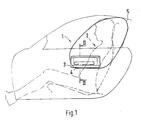
- An impact protection device 1 for an occupant 2 of a vehicle comprises a Housing 3, a gas generator 4 and an inflatable gas bag 5, which Housing 3, the gas generator 4 and the gas bag 5 a prefabricated installation module 6 form.
- Fig. 1 the gas bag 5 is shown in the inflated operating position.
- the impact protection device 1 is as Side impact protection device is formed and the prefabricated installation module 6 attached to a door inner panel 7 of a side door 8. Upstream of the installation module 6 is a door trim 9 on which an upright wall is covered by a cover 10 closable outlet opening 11 is provided for the inflated gas bag 5 is.
- the cover 10 comprises two pivotable flap halves, which one Target tear point are connected to each other.
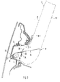
- the gas bag 5 consists of two approximately the same large fabric layers 12, 13 lying one above the other with two Small spaced circumferential seams 14 connected to each other are. At least one tether 15 is provided within the gas bag 5 with which the filling shape of the gas bag 5 is controlled when inflated.
- the invention is an end 16 of the tether 15 with the gas generator 4 and the other end 17 of the tether 15 with the occupant 2 facing Fabric layer 13 of the gas bag 5 connected.
- the gas bag 5 is through a internal partition 18 in two interconnected chambers 19, 20 divided.
- the two chambers 19, 20 arranged one above the other, the first, lower chamber 19 the Is assigned to the occupant's chest / pelvic area (thoracic chamber).
- the gas generator 4 is formed by an elongated tube generator 21 formed, which is arranged within the first chamber 19 and locally with this connected is.
- the tube generator 21 is on a generator support 22 in the axial and attached in the radial direction.
- Generator carrier 22 On the side facing away from the tube generator 21
- Generator carrier 22 are a plurality of spaced bolts 23 attached for fixing the tube generator 21 to the housing 3 and also for fastening serve the gas bag 5 and the inner tether 15.
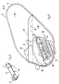
- the Tube generator 21 is together with the generator support 22 by a rectangular mounting opening 24 of the fabric layer 12 in the interior of the gas bag 5 introduced and then the generator-side end 16 of the inner Tether 15 hooked onto the three bolts 23. For this are on the tether 15 corresponding circular holes are provided. To facilitate assembly can the tether 15 in the region of the generator end 16 on the Fabric layer 12 are attached with a fixing seam (not shown in detail).
- the adjacent fabric layer 12 of the gas bag 5 inside and outside with two reinforcement layers on top of each other 25, 26 provided with the centrally received fabric layer 12 via a double seam are connected.
- the inner reinforcement layers are 25 and outer reinforcement layers are designated by 26.
- the assembly opening 24 for the gas generator 4 are both on the fabric layer 12 and on the Reinforcement layers 25, 26 cut-out, pivotable tab sections formed, the assembly opening 24 after the insertion of the gas generator 4 close again.
- the tab portions of the outer reinforcement layers 26 are only with its upper edge firmly connected to it, whereas the tab portions of the inner reinforcement layers 25 only with their lower edge in one piece to the inner Reinforcement layers are connected.
- the two lobe sections of the middle Fabric layer 12 are on the left and right edges of the mounting opening 24 with the Fabric layer 12 connected. This arrangement results in an offset Overlap of the tab sections after inserting the gas generator 4.
- the bolts 23 of the Generator carrier 22 by corresponding circular recesses in the Fabric layer 12 and the reinforcement layers 25, 26 passed and the gas bag 5 is folded up.
- One also attached to the bolt 23 with at one end connected to the gas bag 5 protective cover 30 envelops the folded gas bag 5.
- the protective cover 30 has a predetermined breaking point 31, which tears when the gas bag 5 is inflated.
- the folded gas bag 5 with the internal gas generator 4 is inserted into the housing 3, the Bolt 23 inserted through openings in the adjacent housing 3 become.
- Tether 15 is formed in two layers. In a partial area 33 of his The longitudinal extension of the tether 15 is folded in several layers, the Layers of the tether 15 lying one above the other can be released by a tear seam 34 are interconnected.
- the tear seam 34 is on both sides by external Protective layers 35, 36 covered, the end facing the gas generator 4 both protective layers 35, 36 are sewn to the tether 15 (FIG. 3).
- the end 17 of the tether 15 facing the occupant 2 is below Interposition of a rectangular inner reinforcement layer 37 to the external fabric layer 13 of the gas bag 5 facing the occupant connected, the reinforcing layer 37 having a substantially greater width has as the tether 15.
- the tether 15 is between the reinforcing layer 37 and fabric layer 13 passed through, the reinforcing layer 37 with the Fabric layer 13 is connected via two circumferential connecting seams.
- At the lower chamber 19 and optionally on the upper chamber 20 of the gas bag 5 can locally circular darts 38 between the two fabric layers 12, 13 of the Gas bags 5 for the defined inflation of the corresponding chamber 19, 20 be provided, the darts 38 when exceeding a predetermined Release internal pressure.
- On the partition 18 between the two chambers 19, 20 at least one flow opening 39 is provided through which the gas flow after the Inflation of the first chamber 19 can flow into the second chamber 20.
- the lower chamber 19 When the airbag 5 is inflated, the lower chamber 19 is directed towards the occupant moved, the path and the speed of the Airbag 5 is reduced in time (see Fig. 3). From a defined internal pressure in the first chamber 19 tears the tear seam 34 of the tether 15 and the first Chamber 19 or gas bag 5 is moved further in the direction of occupant 2.
- the Airbag 5 according to the invention has no outside outflow openings.
Landscapes
- Engineering & Computer Science (AREA)
- Mechanical Engineering (AREA)
- Air Bags (AREA)
Claims (7)
- Dispositif de protection contre une collision latérale pour un passager d'un véhicule comportant un sac gonflable (5) coopérant avec un générateur de gaz (4), lequel est pourvu d'au moins une bande de retenue située à l'intérieur, et comprend deux chambres (19, 20) superposées communiquant entre elles, une première chambre (19) étant associée à la région de la poitrine/du bassin du passager et une deuxième chambre (10) à la région de la tête du passager, et la première chambre (19) communiquant avec le générateur de gaz (4) étant gonflée en cas de collision avant la deuxième chambre (20), le générateur de gaz (4) étant disposé éloigné du bord périphérique du sac gonflable (5), caractérisé par la combinaison des caractéristiques suivantes :le sac gonflable (5) est partagé par une cloison (18) située à l'intérieur dans les deux chambres (19, 20) superposées -comme générateur de gaz (4) est prévu un générateur tubulaire (21) allongé reçu par un support de générateur (22), le générateur tubulaire (21) étant disposé avec le support de générateur (22) entièrement à l'intérieur de la première chambre (19) du sac gonflable (5) et étant relié localement à celui-ci -la bande de retenue (15) pour la commande de la forme de remplissage du sac gonflable (5) est réalisée à deux couches, est pourvue d'une couture arrachable (34) et s'étend à l'intérieur de la première chambre (19), une extrémité (16) de la bande de retenue ( 15) étant fixée au support de générateur (22) et l'autre extrémité (17) étant reliée à une couche de tissu (13) du sac gonflable (5) tournée vers le passager -la bande de retenue (15) est pourvue, au moins dans la zone de la couture arrachable (34), de couches de protection (35, 36) situées à l'extérieur -sur la couche de tissu (12) tournée vers un boítier (3) du sac gonflable (5) est prévue, dans la zone de la première chambre (19), une ouverture de montage (24) rectangulaire pour y insérer le générateur tubulaire (21) -la couche de tissu (12) du sac gonflable (5) est pourvue au voisinage de l'ouverture de montage (24), sur le côté intérieur et le côté extérieur, de deux pattes de renfort (25, 26) superposées -l'ouverture de montage (24) peut être fermée par des segments de patte se chevauchant de la couche de tissu (12) et des couches de renfort (25, 26).
- Dispositif de protection contre une collision latérale selon la revendication 1, caractérisé en ce que la bande de retenue (15) est reliée à l'extrémité tournée vers le passager (2), par une couche de renfort (37) intérieure, à la couche de tissu (13) correspondante du sac gonflable (5), la couche de renfort intérieure (37) présentant une largeur sensiblement plus grande que la bande de retenue (15).
- Dispositif de protection contre une collision latérale selon la revendication 1, caractérisé en ce que pour la fixation du générateur tubulaire (21), il est prévu un support de générateur (22) allongé qui présente des boulons (23) dépassant localement sur le côté tourné à l'opposé du générateur tubulaire (21).
- Dispositif de protection contre une collision latérale selon les revendications 1 et 3, caractérisé en ce qu'aux boulons (23) du support de générateur (22) sont accrochés l'extrémité (16) côté générateur de gaz de la bande de retenue (15) et le sac gonflable (5), et en ce que pour la fixation du sac gonflable (5) et du générateur de gaz (4), les boulons (23) saillants passent à travers des ouvertures du boítier (3) voisin, des écrous (32) étant vissés de l'extérieur sur les portions filetées dépassantes des boulons (23).
- Dispositif de protection contre une collision latérale selon une ou plusieurs des revendications précédentes, caractérisé en ce qu'entre les deux couches de tissu (12, 13) reliées entre elles sur les bords du sac gonflable (5) est prévue, dans la zone de la première chambre (19), au moins une pince (38) qui relie entre elles les deux couches de tissu (12, 13), la pince (38) s'ouvrant au-dessus d'une pression définie à l'intérieur de la première chambre (19).
- Dispositif de protection contre une collision latérale selon une ou plusieurs des revendications précédentes, caractérisé en ce que dans la zone de la deuxième chambre (20) du sac gonflable (5), tournée vers la tête du passager (2), il est prévu des pinces et/ou au moins une bande de retenue pourvue d'une couture arrachable, pour faciliter le déploiement.
- Dispositif de protection contre une collision latérale selon une ou plusieurs des revendications précédentes, caractérisé en ce que la bande de retenue (15) est fixée, par une couture de fixation, à la couche de tissu (12) du sac gonflable (5), dans la zone de la fixation du générateur tubulaire (21).
Applications Claiming Priority (2)
| Application Number | Priority Date | Filing Date | Title |
|---|---|---|---|
| DE19720588A DE19720588A1 (de) | 1997-05-16 | 1997-05-16 | Aufprallschutzeinrichtung für einen Insassen eins Fahrzeuges |
| DE19720588 | 1997-05-16 |
Publications (2)
| Publication Number | Publication Date |
|---|---|
| EP0878358A1 EP0878358A1 (fr) | 1998-11-18 |
| EP0878358B1 true EP0878358B1 (fr) | 2003-12-17 |
Family
ID=7829673
Family Applications (1)
| Application Number | Title | Priority Date | Filing Date |
|---|---|---|---|
| EP98106937A Expired - Lifetime EP0878358B1 (fr) | 1997-05-16 | 1998-04-16 | Dispositif de protection en cas d'accident pour un occupant de véhicule automobile |
Country Status (5)
| Country | Link |
|---|---|
| US (1) | US6073959A (fr) |
| EP (1) | EP0878358B1 (fr) |
| JP (1) | JPH10324212A (fr) |
| KR (1) | KR19980087094A (fr) |
| DE (2) | DE19720588A1 (fr) |
Families Citing this family (32)
| Publication number | Priority date | Publication date | Assignee | Title |
|---|---|---|---|---|
| DE29721678U1 (de) * | 1997-11-26 | 1998-02-05 | Petri Ag | Vorrichtung zur Beeinflussung der Entfaltung eines Gassacks eines Airbagmoduls |
| JP3488249B2 (ja) * | 1998-09-14 | 2004-01-19 | デルフィ オートモーティブ システムズ ソンウ コーポレイション | エアバッグ構造体 |
| US6612610B1 (en) * | 1998-09-18 | 2003-09-02 | Honda Giken Kogyo Kabushiki Kaisha | Air bag device |
| DE29822159U1 (de) * | 1998-12-11 | 1999-05-12 | Trw Repa Gmbh | Gassack-Seitenaufprall-Schutzeinrichtung |
| DE29915820U1 (de) * | 1999-09-08 | 2000-01-13 | TRW Occupant Restraint Systems GmbH & Co. KG, 73553 Alfdorf | Seitenaufprall-Schutzeinrichtung |
| DE60018158T8 (de) * | 2000-02-01 | 2006-08-24 | Delphi Automotive Systems Sungwoo Corp. | Seitenairbagsystem und dessen Herstellungsverfahren |
| DE10018170B4 (de) * | 2000-04-12 | 2012-10-31 | Audi Ag | Luftsackanordnung |
| JP4356191B2 (ja) * | 2000-04-25 | 2009-11-04 | タカタ株式会社 | エアバッグ装置 |
| CN1290728C (zh) * | 2000-07-07 | 2006-12-20 | 丰田合成株式会社 | 保护膝用安全气囊装置 |
| CN1226156C (zh) | 2000-07-07 | 2005-11-09 | 丰田合成株式会社 | 保护膝用气囊装置 |
| US7182365B2 (en) * | 2000-07-07 | 2007-02-27 | Toyoda Gosei Co., Ltd. | Air bag device for knee protection |
| DE20018091U1 (de) * | 2000-10-23 | 2001-03-08 | Trw Repa Gmbh | Fahrzeuginsassen-Schutzsystem |
| US7134691B2 (en) | 2001-05-23 | 2006-11-14 | Delphi Technologies, Inc. | Air bag cushion including break-away tethers |
| DE10257249A1 (de) * | 2002-12-07 | 2004-07-08 | Dr.Ing.H.C. F. Porsche Ag | Sicherheitseinrichtung für Insassen eines Kraftfahrzeugs |
| US6854759B2 (en) * | 2003-04-09 | 2005-02-15 | Trw Vehicle Safety Systems Inc. | Apparatus including an inflatable knee bag |
| GB2408023A (en) * | 2003-11-11 | 2005-05-18 | Autoliv Dev | Side air bag with internal tether |
| DE102005002085B4 (de) * | 2004-03-17 | 2013-09-05 | TAKATA Aktiengesellschaft | Seitenairbageinrichtung |
| DE102004013036B4 (de) | 2004-03-26 | 2011-04-14 | Faurecia Innenraum Systeme Gmbh | Vorrichtung zum Kopf- und/oder Schulteraufprallschutz bei einer Seitenkollision und/oder einem Überschlag |
| US7222875B2 (en) * | 2004-06-28 | 2007-05-29 | Lear Corporation | Close out retainer for side air bag chute |
| DE102005024268A1 (de) * | 2005-05-20 | 2006-11-23 | Polytec Interior Gmbh | Sicherheitseinrichtung |
| US20070057491A1 (en) * | 2005-09-09 | 2007-03-15 | Trw Vehicle Safety Systems Inc. | Vehicle occupant protection apparatus located in the door of a vehicle |
| DE102005050935B4 (de) * | 2005-10-21 | 2011-03-24 | Autoliv Development Ab | Seitenaufprallschutzeinrichtung |
| US7578518B2 (en) * | 2005-11-17 | 2009-08-25 | Honda Motor Co., Ltd. | Occupant protection device |
| KR100636641B1 (ko) * | 2005-11-23 | 2006-10-23 | 현대모비스 주식회사 | 조수석 에어백 모듈 |
| DE202006010362U1 (de) * | 2006-06-29 | 2006-09-14 | Takata-Petri Ag | Seitengassackanordnung |
| US20080164681A1 (en) * | 2007-01-08 | 2008-07-10 | Faurecia Interior Systems U.S.A., Inc. | Apparatus and Methods for Passive Restraint |
| JP2008195355A (ja) * | 2007-02-15 | 2008-08-28 | Takata Corp | エアバッグの折り畳み方法、エアバッグの収容方法及びエアバッグ装置 |
| DE102008036353B4 (de) * | 2008-08-05 | 2016-05-12 | Autoliv Development Ab | Gassackeinrichtung |
| DE102008057169B4 (de) * | 2008-11-13 | 2015-11-19 | Autoliv Development Ab | Gassackanordnung für ein Kraftfahrzeug mit abgedichteter Gasgeneratoranbindung und Verfahren zur Montage des Gasgenerators in den Gassack |
| DE102009012364B4 (de) * | 2009-03-09 | 2017-04-27 | Trw Airbag Systems Gmbh | Baugruppe mit einem Gasgenerator |
| JP2014104965A (ja) * | 2012-11-30 | 2014-06-09 | Toyoda Gosei Co Ltd | サイドエアバッグ装置 |
| JP6946986B2 (ja) * | 2017-12-01 | 2021-10-13 | トヨタ自動車株式会社 | 後席サイドエアバッグ装置 |
Family Cites Families (27)
| Publication number | Priority date | Publication date | Assignee | Title |
|---|---|---|---|---|
| DE2333888A1 (de) * | 1973-07-03 | 1974-01-31 | Nissan Motor | Sicherheitsvorrichtung zum schutz eines fahrzeuginsassen bei einem zusammenstoss |
| DE2722551A1 (de) * | 1977-05-18 | 1978-11-30 | Daimler Benz Ag | Aufblasbares aufprallschutzkissen |
| US4153273A (en) * | 1978-04-14 | 1979-05-08 | General Motors Corporation | Occupant restraint cushion system |
| US4966389A (en) * | 1989-03-28 | 1990-10-30 | Juichiro Takada | Inflatable air bag for protection of a vehicle occupant |
| JPH0367749A (ja) * | 1989-08-08 | 1991-03-22 | Toyoda Gosei Co Ltd | エアバツグ装置におけるエアバツグ |
| JPH04310449A (ja) * | 1991-04-10 | 1992-11-02 | Asahi Chem Ind Co Ltd | 吊り紐付きエアバッグ |
| US5129675A (en) * | 1991-05-02 | 1992-07-14 | General Motors Corporation | Occupant restraint cushion |
| US5149130A (en) * | 1991-05-28 | 1992-09-22 | General Motors Corporation | Liner for inflatable occupant restraint cushion |
| US5205584A (en) * | 1991-07-05 | 1993-04-27 | Honda Giken Kogyo Kabushiki Kaisha | Air bag system and process for producing the same |
| US5421610A (en) * | 1991-07-26 | 1995-06-06 | Airbags International Limited | Inflatable airbag |
| US5174601A (en) * | 1991-08-29 | 1992-12-29 | General Motors Corporation | Inflation gas flow directing member for air bag system |
| DE4142326B4 (de) * | 1991-12-20 | 2004-07-22 | Bayerische Motoren Werke Ag | Airbag für ein Kraftfahrzeug |
| US5358273A (en) * | 1992-03-09 | 1994-10-25 | Toyo Tire & Rubber Co., Ltd. | Inflatable bags for airbag passive restraint systems for driver and method for production thereof |
| US5310214A (en) * | 1992-04-02 | 1994-05-10 | Talley Automotive Products, Inc. | Air bag system for restraining movement of an adult and/or a child |
| US5249825A (en) * | 1992-07-13 | 1993-10-05 | General Motors Corporation | Air bag with releasable tethers |
| JP2629531B2 (ja) * | 1992-08-28 | 1997-07-09 | 池田物産株式会社 | エアバッグ装置のエアバッグ本体 |
| MX9304559A (es) * | 1992-09-01 | 1994-03-31 | Morton Int Inc | Cuerdas con costuras rascables para cojin de bolsa inflable. |
| US5308113A (en) * | 1992-10-09 | 1994-05-03 | Trw Vehicle Safety Systems Inc. | Airbag inflation-controlling member |
| DE4315142C3 (de) * | 1993-05-07 | 2000-01-05 | Daimler Chrysler Ag | Gassack für ein Kraftfahrzeug |
| JPH07149197A (ja) * | 1993-11-29 | 1995-06-13 | Ikeda Bussan Co Ltd | エアバッグ装置のエアバッグ本体 |
| DE4423552A1 (de) * | 1994-07-05 | 1996-01-11 | Artur Foehl | Gassackbefestigung an einem in den Gassack einzusetzenden Gehäuse |
| DE4430412C1 (de) * | 1994-08-26 | 1995-10-12 | Porsche Ag | Seitenaufprallschutzeinrichtung für einen Insassen eines Fahrzeuges |
| DE4443027A1 (de) * | 1994-12-02 | 1996-06-05 | Trw Repa Gmbh | Seitenaufprall-Gassack |
| US5586782A (en) * | 1995-06-26 | 1996-12-24 | Alliedsignal Inc. | Dual pressure side impact air bag |
| DE29517372U1 (de) * | 1995-11-02 | 1996-02-01 | Trw Repa Gmbh | Gassack-Seitenaufprall-Schutzeinrichtung |
| US5848805A (en) * | 1996-03-29 | 1998-12-15 | Toyo Tire & Rubber Co., Ltd. | Bag for an airbag for a vehicle |
| DE29701337U1 (de) * | 1997-01-14 | 1997-03-20 | Petri Ag, 63743 Aschaffenburg | Anordnung zur Befestigung eines Gasgenerators, insbesondere eines Rohrgasgenerators in einem Gehäuse, insbesondere in einem Diffusor eines Airbagmoduls |
-
1997
- 1997-05-16 DE DE19720588A patent/DE19720588A1/de not_active Ceased
-
1998
- 1998-04-16 EP EP98106937A patent/EP0878358B1/fr not_active Expired - Lifetime
- 1998-04-16 DE DE59810435T patent/DE59810435D1/de not_active Expired - Fee Related
- 1998-05-13 JP JP10130111A patent/JPH10324212A/ja active Pending
- 1998-05-15 KR KR1019980017545A patent/KR19980087094A/ko not_active Application Discontinuation
- 1998-05-18 US US09/080,252 patent/US6073959A/en not_active Expired - Fee Related
Also Published As
| Publication number | Publication date |
|---|---|
| DE19720588A1 (de) | 1998-11-19 |
| DE59810435D1 (de) | 2004-01-29 |
| JPH10324212A (ja) | 1998-12-08 |
| EP0878358A1 (fr) | 1998-11-18 |
| US6073959A (en) | 2000-06-13 |
| KR19980087094A (ko) | 1998-12-05 |
Similar Documents
| Publication | Publication Date | Title |
|---|---|---|
| EP0878358B1 (fr) | Dispositif de protection en cas d'accident pour un occupant de véhicule automobile | |
| DE60023205T2 (de) | Luftsack | |
| EP0999101B1 (fr) | Dispositif de protection à sac gonflable contre des chocs latéraux | |
| DE69304168T2 (de) | Seitenaufprallairbag | |
| DE102005011676B4 (de) | Vorhang-Gassack und Kraftfahrzeug | |
| DE69004355T2 (de) | Leichtbaugehäuse für Aufblasvorrichtungen auf der Beifahrerseite. | |
| DE4430412C1 (de) | Seitenaufprallschutzeinrichtung für einen Insassen eines Fahrzeuges | |
| WO2019121222A1 (fr) | Système de protection des occupants d'un véhicule et procédé permettant de faire fonctionner un système de protection des occupants d'un véhicule | |
| DE19622225B4 (de) | Airbag mit Haltemitteln | |
| DE10000768B4 (de) | Aufblasbare Seitenvorhanganordnung für ein Fahrzeug | |
| EP0897837B1 (fr) | Procédé de pliage d'un coussin gonflable d'un dispositif de protection de choc | |
| EP3697649B1 (fr) | Système de retenue d'occupant de véhicule muni d'un module airbag | |
| DE4240760A1 (fr) | ||
| EP1592585B1 (fr) | Dispositif de protection des occupants d'un vehicule | |
| DE102016005606A1 (de) | Airbag-abdeckung mit integrierter lenkbahn | |
| DE102004038459B4 (de) | Airbagmodul zum Schutz eines Kraftfahrzeuginsassen | |
| EP0878359B1 (fr) | Dispositif de protection contre le choc latéral pour occupant de véhicule | |
| WO2019076674A1 (fr) | Enveloppe d'un coussin gonflable d'un système de retenue d'occupant d'un véhicule et procédé pour emballer un coussin gonflable dans une enveloppe | |
| EP1426246B1 (fr) | Dispositif de sécurité pour passagers | |
| DE69834722T2 (de) | Sitzintegrierter luftsack-entfaltungsdeckel | |
| EP1426244B1 (fr) | Véhicule avec structure de carrosserie et un dispostif de protection en cas de choc latéral | |
| DE10039800B4 (de) | Fahrzeugdach, insbesondere für ein Kraftfahrzeug | |
| EP0878361A2 (fr) | Dispositif de protection en cas de choc latéral pour l'occupant d'un véhicule | |
| EP1113949B1 (fr) | Module sac gonflable doté d'un générateur de gaz à plusieurs étapes | |
| DE102004023780B4 (de) | Airbageinrichtung |
Legal Events
| Date | Code | Title | Description |
|---|---|---|---|
| PUAI | Public reference made under article 153(3) epc to a published international application that has entered the european phase |
Free format text: ORIGINAL CODE: 0009012 |
|
| AK | Designated contracting states |
Kind code of ref document: A1 Designated state(s): DE FR GB IT |
|
| AX | Request for extension of the european patent |
Free format text: AL;LT;LV;MK;RO;SI |
|
| 17P | Request for examination filed |
Effective date: 19990410 |
|
| AKX | Designation fees paid |
Free format text: DE FR GB IT |
|
| 17Q | First examination report despatched |
Effective date: 20010730 |
|
| GRAH | Despatch of communication of intention to grant a patent |
Free format text: ORIGINAL CODE: EPIDOS IGRA |
|
| GRAS | Grant fee paid |
Free format text: ORIGINAL CODE: EPIDOSNIGR3 |
|
| GRAA | (expected) grant |
Free format text: ORIGINAL CODE: 0009210 |
|
| AK | Designated contracting states |
Kind code of ref document: B1 Designated state(s): DE FR GB IT |
|
| REG | Reference to a national code |
Ref country code: GB Ref legal event code: FG4D Free format text: NOT ENGLISH |
|
| REF | Corresponds to: |
Ref document number: 59810435 Country of ref document: DE Date of ref document: 20040129 Kind code of ref document: P |
|
| GBT | Gb: translation of ep patent filed (gb section 77(6)(a)/1977) |
Effective date: 20040116 |
|
| ET | Fr: translation filed | ||
| PLBE | No opposition filed within time limit |
Free format text: ORIGINAL CODE: 0009261 |
|
| STAA | Information on the status of an ep patent application or granted ep patent |
Free format text: STATUS: NO OPPOSITION FILED WITHIN TIME LIMIT |
|
| 26N | No opposition filed |
Effective date: 20040920 |
|
| PGFP | Annual fee paid to national office [announced via postgrant information from national office to epo] |
Ref country code: DE Payment date: 20070405 Year of fee payment: 10 |
|
| PGFP | Annual fee paid to national office [announced via postgrant information from national office to epo] |
Ref country code: GB Payment date: 20070426 Year of fee payment: 10 |
|
| PGFP | Annual fee paid to national office [announced via postgrant information from national office to epo] |
Ref country code: IT Payment date: 20070614 Year of fee payment: 10 |
|
| PGFP | Annual fee paid to national office [announced via postgrant information from national office to epo] |
Ref country code: FR Payment date: 20070416 Year of fee payment: 10 |
|
| GBPC | Gb: european patent ceased through non-payment of renewal fee |
Effective date: 20080416 |
|
| PG25 | Lapsed in a contracting state [announced via postgrant information from national office to epo] |
Ref country code: DE Free format text: LAPSE BECAUSE OF NON-PAYMENT OF DUE FEES Effective date: 20081101 |
|
| REG | Reference to a national code |
Ref country code: FR Ref legal event code: ST Effective date: 20081231 |
|
| PG25 | Lapsed in a contracting state [announced via postgrant information from national office to epo] |
Ref country code: FR Free format text: LAPSE BECAUSE OF NON-PAYMENT OF DUE FEES Effective date: 20080430 |
|
| PG25 | Lapsed in a contracting state [announced via postgrant information from national office to epo] |
Ref country code: GB Free format text: LAPSE BECAUSE OF NON-PAYMENT OF DUE FEES Effective date: 20080416 |
|
| PG25 | Lapsed in a contracting state [announced via postgrant information from national office to epo] |
Ref country code: IT Free format text: LAPSE BECAUSE OF NON-PAYMENT OF DUE FEES Effective date: 20080416 |