EP0877458B1 - Dispositif de connexion et de montage - Google Patents
Dispositif de connexion et de montage Download PDFInfo
- Publication number
- EP0877458B1 EP0877458B1 EP98106624A EP98106624A EP0877458B1 EP 0877458 B1 EP0877458 B1 EP 0877458B1 EP 98106624 A EP98106624 A EP 98106624A EP 98106624 A EP98106624 A EP 98106624A EP 0877458 B1 EP0877458 B1 EP 0877458B1
- Authority
- EP
- European Patent Office
- Prior art keywords
- switch unit
- annular flange
- groove
- flange
- switch
- Prior art date
- Legal status (The legal status is an assumption and is not a legal conclusion. Google has not performed a legal analysis and makes no representation as to the accuracy of the status listed.)
- Expired - Lifetime
Links
- 230000002093 peripheral effect Effects 0.000 claims description 4
- 230000005489 elastic deformation Effects 0.000 claims description 2
- 239000013013 elastic material Substances 0.000 claims 1
- 239000011521 glass Substances 0.000 description 21
- 239000012790 adhesive layer Substances 0.000 description 5
- 238000004026 adhesive bonding Methods 0.000 description 2
- 238000003780 insertion Methods 0.000 description 2
- 230000037431 insertion Effects 0.000 description 2
- 239000000463 material Substances 0.000 description 2
- 239000000853 adhesive Substances 0.000 description 1
- 230000001070 adhesive effect Effects 0.000 description 1
- 230000006835 compression Effects 0.000 description 1
- 238000007906 compression Methods 0.000 description 1
- 238000009833 condensation Methods 0.000 description 1
- 230000005494 condensation Effects 0.000 description 1
- 230000006735 deficit Effects 0.000 description 1
- 230000001419 dependent effect Effects 0.000 description 1
- 238000005553 drilling Methods 0.000 description 1
- 238000009434 installation Methods 0.000 description 1
- 239000010410 layer Substances 0.000 description 1
- 238000000034 method Methods 0.000 description 1
- 238000002360 preparation method Methods 0.000 description 1
- 238000004080 punching Methods 0.000 description 1
- 238000007789 sealing Methods 0.000 description 1
- 230000035945 sensitivity Effects 0.000 description 1
- 239000007787 solid Substances 0.000 description 1
- 230000007704 transition Effects 0.000 description 1
Images
Classifications
-
- H—ELECTRICITY
- H02—GENERATION; CONVERSION OR DISTRIBUTION OF ELECTRIC POWER
- H02B—BOARDS, SUBSTATIONS OR SWITCHING ARRANGEMENTS FOR THE SUPPLY OR DISTRIBUTION OF ELECTRIC POWER
- H02B1/00—Frameworks, boards, panels, desks, casings; Details of substations or switching arrangements
- H02B1/26—Casings; Parts thereof or accessories therefor
-
- H—ELECTRICITY
- H03—ELECTRONIC CIRCUITRY
- H03K—PULSE TECHNIQUE
- H03K17/00—Electronic switching or gating, i.e. not by contact-making and –breaking
- H03K17/94—Electronic switching or gating, i.e. not by contact-making and –breaking characterised by the way in which the control signals are generated
- H03K17/945—Proximity switches
- H03K2017/9455—Proximity switches constructional details
Definitions
- the invention relates to a connection and mounting arrangement for a flat switch unit.
- Switches and trams at the passengers by touching a corresponding predetermined and marked area on the vehicle outside open the door or on a surface in the vehicle interior generate a preparation signal that leads that at the next stop the concerned Door is opened when the driver of the vehicle enters Generated general enable signal.
- a proximity switch using a him mount the surrounding socket in the through hole of a wall, the Bush is screwed into this hole and on its inner peripheral surface has at least one groove in the assembled state one on the Outer surface of the cylindrical proximity switch provided circumferential groove opposite.
- the connection between the mounting bush and the Proximity switch is made using one in these two opposite each other Grooves inserted O-rings.
- the invention has the object, a connection and To provide mounting arrangement in which it is not necessary in the switch supporting wall to form such a large passage opening.
- the invention provides in the Claim 1 summarized features.
- Another advantage is the fact that the installation and replacement of the switch during the back glass assembly without drilling holes is possible. The usual punching of the entire switch diameter is not required for this type of mounting.
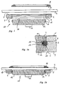
- FIGS. 1 to 1b serves as a mounting flange 2 trained ring for attachment the entire arrangement of a glass 4.
- the mounting flange 2 is at its one End face provided with an adhesive layer 5, with whose help he permanently attached to the glass 4 can be as shown in Fig. 1b.
- the extending through the mounting flange 2 therethrough central opening 6 has a substantially cylindrical Inner surface 7 on, in which one extends over the entire circumference extending annular groove 8 is formed.
- the opening 6 expands frustoconically Outside.
- the switch unit 10 consists of a flat cylindrical Switch housing 12, in which a not visible in the figures Proximity switch is housed so that its sensitive to the approach of a body switch surface in the top in Figs. 1 to 1b End face 11 of the switch housing 12 is located.
- the connection 14, with the help of the proximity switch with a circuit electronics can be connected is in Figs. 1 and 1b shown only schematically.
- the switch housing 12 has a cylindrical outer surface 15, whose diameter is only slightly smaller is the diameter of the inner surface 7 of the mounting flange 2.
- a cylindrical outer surface 15 In the outer surface 15 is a about the entire circumference extending annular groove 16 is formed, for receiving an O-ring 17 made of elastically deformable Material serves.
- Fig. 1a has the Ring groove 16 in the axial direction a height that is slightly smaller than the thickness of the O-ring 17, so that this under slight compression between those in Figs. 1 to 1b upper or lower groove side wall are clamped can.
- the depth of the annular groove 16 perpendicular to the outer surface 15 is dimensioned so that at the bottom surface of the Ring groove 16 fitting O-ring to about a quarter to a third of its thickness over the outer surface 15 radially protrudes outwards.
- the axial distance of the axial center of the annular groove 8 of the coated with adhesive 5 face of the mounting flange 2, as shown in FIG. 1a, is slightly smaller as the axial distance of the axial center of the annular groove 16 from the end face 11. This has the consequence that then, if you the switch housing 12 with the mounting flange. 2 assembled by insertion in the axial direction, without in that the mounting flange 2 is glued to the glass pane 4 is, the end face 11 slightly above the adhesive layer 5 protrudes in the axial direction.
- the mounting flange 2 is present the insertion of the switch housing 12 to the glass 4 glued. This allows the switch housing 12 are not advanced so far in the axial direction, as shown in Fig. 1a. This way it stays the O-ring 17 is deformed somewhat elastically in the way that he directed a glass pane 4 toward Relative force between the mounting flange 2 and the Switch housing 12 generates. Together with the adhesion, the between the appropriately ground and polished end face 11 of the switch housing 12 and the glass sheet 4 is formed in the assembled state, this results in an excellent holder of the switch housing 12 on the mounting flange 2 and the glass 4. At least the air layer between the glass pane 4 and the end face 11 kept so thin that no condensation and when using a capacitive proximity switch no impairment of sensitivity entry.
- a Cover and hand guide ring 18 is provided with the Help an adhesive layer 19 on the glass 4 permanently can be attached and its inner diameter is chosen so that when approaching a body, for example, a human hand a switching operation triggering, in the end face 11 of the switch housing 12 arranged switch surface encloses and visually and tactile clearly marked.
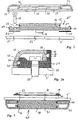
- an annular Mounting flange 21 includes, with the switch housing 12th in a conventional manner, for example, connected by gluing is.
- the mounting flange 21 also made in one piece with the switch housing 12 or be connected in any other way.
- the mounting flange has several continuous in the axial direction Mounting holes 22, of which in section the Fig. 2 and 2a only one is shown.
- the Plate 4 ' on whose in Figs. 2 and 2a upper side the switch housing 12 to be mounted, points here a through opening 23 for the connection 14. Furthermore, in the plate 4 'more continuous Mounting openings 24 are provided, of which in Figs. 2 and 2a also only one is visible. Between the Plate 4 'facing end face of the mounting flange 21 and the plate 4 ', a sealing ring 25 is provided, the mounting holes 22 and mounting holes 24 corresponding has through openings 26.
- FIGS. 2 and 2a are both here the switch housing 12 and the mounting flange 21st cylindrical outer surfaces 15 and 29, in each case one circumferentially circumferential annular groove 16 and 30 for receiving an O-ring 17 or 31 is incorporated.
- the relative dimensions of the annular grooves 16 and 30 in relation to the O-rings 17, 31 are the same as above has been described with reference to Figs. 1 to 1b.
- annular Covering flange 33 is provided, whose continuous Opening 35 two substantially cylindrical inner wall sections 36, 37, whose different diameters each slightly smaller than the outer diameter the cylindrical outer surface 15 of the switch housing 12 and the cylindrical outer surface 29 of the mounting flange 21 are.
- each of these cylindrical Inner wall sections 36, 37 is one in the circumferential direction circumferential annular groove 38 and 39 incorporated, the how one particularly takes the Fig. 2a, such an axial Has position that they are in the assembled state of Ring groove 16 of the switch housing 12 and the annular groove 30th the mounting flange 21 is opposite and for receiving of the annular grooves projecting part of the relevant O-rings 17 and 31, respectively.
- the offset axially opposite annular grooves be that the O-rings 17, 31 in the assembled state remain elastically deformed and thus one to the plate 4 ' to exert directed force on the cover 33.
- Double switch unit 40 is provided, which is a flat cylindrical Switch housing 41 includes, in the two End faces 42, 47 each one approaching Button a corresponding switch arranged is.
- this double switch unit 40 both from the top in Fig. 3 side of Glass plate 4 as well as from the bottom in this figure Pressed "back" ago.
- the substantially cylindrical outer surface of the switch housing 41 here has two with an axial distance arranged, extending in the circumferential direction annular grooves on, in each of which an O-ring 43, 44 housed of which the O-ring 43 is for connecting the Switch housing 41 in the same way with a on the glass 4 glued mounting flange 45 serves as described with reference to Figs. 1 to 1b was, and of which the O-ring 44 according to the Embodiment of Fig. 2 and 2a for holding a Cover flange 46 is provided.
- the synonymous with this Embodiment existing connections, with their help the two housed in the switch housing 41 proximity switch be connected to the associated electronics, are led out laterally and for the sake of simplicity not shown in Fig. 3.
- Double switch unit 40 opposite surface of the Glass 4 a cover and hand guide ring 18 with Help an adhesive layer 19 are glued.
Landscapes
- Engineering & Computer Science (AREA)
- Power Engineering (AREA)
- Switch Cases, Indication, And Locking (AREA)
- Details Of Connecting Devices For Male And Female Coupling (AREA)
- Steering Controls (AREA)
Claims (2)
- Dispositif de connexion et de montage, comprenant une unité de commutation plate 9, au niveau d'une face plate de laquelle est située une surface d'actionnement d'un commutateur, et une bride annulaire entourant l'unité de commutation, la bride annulaire (2 ; 45) est réalisée sous la forme d'une bride de montage pour un montage rapporté d'un côté sur la surface supérieure d'un corps (4, 4') et comprend au moins une surface interne sensiblement cylindrique (7), dans laquelle est réalisée une rainure (8) qui s'étend de manière périphérique, et l'unité de commutation (10, 40) comprend au moins une surface externe sensiblement cylindrique (15), dont le diamètre est légèrement inférieur au diamètre de la surface interne (7) de la bride annulaire (2 ; 45) et dans laquelle est également réalisée une rainure (16) qui s'étend de manière périphérique et est positionnée de telle sorte qu'elle est située environ de manière opposée à la rainure 8 de la bride annulaire (2 ; 45) à l'état monté, un anneau torique (17 ; 43, 44) en matériau élastique insérable avant l'assemblage dans une des deux rainures présentant une épaisseur telle qu'il peut être pressé dans la rainure respective par déformation élastique aussi loin que l'unité de commutation (10, 40) et la bride annulaire (2 ; 45) peuvent être déplacées axialement l'un dans l'autre lors d'un assemblage, et l'anneau torique (17 ; 43, 44) s'étend alors, lorsque les deux rainures en question sont situées de manière environ opposée l'une à l'autre, aussi loin à l'intérieur de l'autre des deux rainures avec une contrainte élastique au moins partielle qui connecte l'unité de commutation (10 ; 40) à la bride annulaire (2 ; 45), et finalement la distance axiale entre le milieu axial de la rainure annulaire (8) prévue dans la bride annulaire (2) et la face frontale de la bride annulaire (2) venant en butée à l'état monté sur la surface supérieure est quelque peu inférieure à la distance axiale entre le milieu axial de la rainure annulaire (16) de l'unité de commutation (10) et la surface frontale (11) de l'unité de commutation (10) venant en butée à l'état monté sur la surface supérieure, de telle sorte qu'à l'état assemblé mais pas à l'état monté sur la surface supérieure, la surface frontale (11) de l'unité de commutation (10) fait légèrement saillie au-delà de la surface frontale de la bride annulaire (2) venant à l'état monté en butée sur la surface supérieure.
- Dispositif de connexion et de montage selon la revendication 1, caractérisé en ce que l'unité de commutation (40) est pourvue d'une autre rainure périphérique pour un anneau torique (44), qui sert à la connexion de l'unité de commutation (40) avec une bride de recouvrement annulaire (46).
Applications Claiming Priority (2)
| Application Number | Priority Date | Filing Date | Title |
|---|---|---|---|
| DE19718807A DE19718807C1 (de) | 1997-05-03 | 1997-05-03 | Verbindungs- und Montageanordnung |
| DE19718807 | 1997-05-03 |
Publications (3)
| Publication Number | Publication Date |
|---|---|
| EP0877458A2 EP0877458A2 (fr) | 1998-11-11 |
| EP0877458A3 EP0877458A3 (fr) | 1999-02-10 |
| EP0877458B1 true EP0877458B1 (fr) | 2005-11-23 |
Family
ID=7828582
Family Applications (1)
| Application Number | Title | Priority Date | Filing Date |
|---|---|---|---|
| EP98106624A Expired - Lifetime EP0877458B1 (fr) | 1997-05-03 | 1998-04-09 | Dispositif de connexion et de montage |
Country Status (2)
| Country | Link |
|---|---|
| EP (1) | EP0877458B1 (fr) |
| DE (1) | DE19718807C1 (fr) |
Families Citing this family (4)
| Publication number | Priority date | Publication date | Assignee | Title |
|---|---|---|---|---|
| EP2552031A1 (fr) * | 2011-07-26 | 2013-01-30 | EAO Holding AG | Commutateur d'ouverture de porte |
| FR3007156B1 (fr) * | 2013-06-14 | 2015-12-25 | Crouzet Automatismes | Bouton, assemblage de bouton commande et procede de montage d'un tel assemblage |
| EP3736985A1 (fr) | 2019-05-10 | 2020-11-11 | Captron Electronic GmbH | Interrupteur éclairé |
| NL2033532B1 (en) | 2022-11-15 | 2024-05-28 | Ventura Systems C V | Sensor door button being attachable to a window panel of a vehicle door. |
Family Cites Families (4)
| Publication number | Priority date | Publication date | Assignee | Title |
|---|---|---|---|---|
| DE3636575A1 (de) * | 1986-10-28 | 1988-05-05 | Standard Elektrik Lorenz Ag | Drehschalter |
| DE8902044U1 (de) * | 1989-02-21 | 1989-05-11 | Pepperl & Fuchs Gmbh, 6800 Mannheim | Näherungsschalter |
| DE4202084A1 (de) * | 1992-01-27 | 1993-01-28 | Herbert Mitscherling | Variopanel fuer elektrotechnische und elektronische schaltanlagen zum einbau in schalttafeln |
| DE4208087C1 (en) * | 1992-03-13 | 1993-04-29 | K.A. Schmersal Gmbh & Co., 5600 Wuppertal, De | Electromechanical push-button switch for vehicle door - has groove on outer circumference of cylindrical housing for snap-fitting O=ring installed on door or similar |
-
1997
- 1997-05-03 DE DE19718807A patent/DE19718807C1/de not_active Expired - Lifetime
-
1998
- 1998-04-09 EP EP98106624A patent/EP0877458B1/fr not_active Expired - Lifetime
Also Published As
| Publication number | Publication date |
|---|---|
| EP0877458A2 (fr) | 1998-11-11 |
| EP0877458A3 (fr) | 1999-02-10 |
| DE19718807C1 (de) | 1998-09-10 |
Similar Documents
| Publication | Publication Date | Title |
|---|---|---|
| EP0937311B1 (fr) | Dispositif de fixation d'un capteur de distance sur un vehicule automobile | |
| DE602004002232T2 (de) | Elektronisches Gerät | |
| DE3722069A1 (de) | Signalhornschaltvorrichtung fuer ein steuerrad | |
| EP0749136B1 (fr) | Commutateur pour ouvrir une porte | |
| WO2001036903A1 (fr) | Capteur de deplacement a cable de mesure | |
| EP0411230B1 (fr) | Dispositif de mesure de pression | |
| DE202004021354U1 (de) | Elastische Kontaktelemente | |
| EP0877458B1 (fr) | Dispositif de connexion et de montage | |
| DE4116779C2 (de) | Unterdruck-Bremskraftverstärker | |
| DE4117303A1 (de) | Lenkrad | |
| DE3605388C2 (de) | Elektrohydraulische Schaltvorrichtung | |
| DE3803041A1 (de) | Einrichtung zur druckanzeige | |
| DE9113754U1 (de) | Elektrischer Kurzhub-Drucktaster | |
| DE3437778C2 (fr) | ||
| DE19737909B4 (de) | Tastschalter mit Ansatz | |
| EP0875972B1 (fr) | Dispositif pour la detection des arcs dans des appareils de commutation électriques | |
| EP1052748A1 (fr) | Dispositif de commande monté sur une plaque frontale | |
| EP0604835A1 (fr) | Robinet à papillon | |
| DE2164652A1 (de) | Elektrischer schalter | |
| DE3220584A1 (de) | Dichtelement fuer eine schraubverbindung | |
| DE1916595B2 (fr) | ||
| EP0856863A2 (fr) | Actionneur pivotable pour un interrupteur de sécurité | |
| DE4128017C2 (de) | Kurzhub-Drucktaster | |
| DE9400632U1 (de) | Schalter | |
| AT397012B (de) | Einstellvorrichtung für ein gerät mit elektrischer regeleinrichtung |
Legal Events
| Date | Code | Title | Description |
|---|---|---|---|
| PUAI | Public reference made under article 153(3) epc to a published international application that has entered the european phase |
Free format text: ORIGINAL CODE: 0009012 |
|
| AK | Designated contracting states |
Kind code of ref document: A2 Designated state(s): FR GB IT |
|
| AX | Request for extension of the european patent |
Free format text: AL;LT;LV;MK;RO;SI |
|
| PUAL | Search report despatched |
Free format text: ORIGINAL CODE: 0009013 |
|
| AK | Designated contracting states |
Kind code of ref document: A3 Designated state(s): AT BE CH CY DE DK ES FI FR GB GR IE IT LI LU MC NL PT SE |
|
| AX | Request for extension of the european patent |
Free format text: AL;LT;LV;MK;RO;SI |
|
| K1C1 | Correction of patent application (title page) published |
Effective date: 19981111 |
|
| RAP3 | Party data changed (applicant data changed or rights of an application transferred) |
Owner name: CAPTRON ELECTRONIC GMBH |
|
| 17P | Request for examination filed |
Effective date: 19990311 |
|
| K1C3 | Correction of patent application (complete document) published |
Effective date: 19981111 |
|
| D17P | Request for examination filed (deleted) | ||
| R17P | Request for examination filed (corrected) |
Effective date: 19990406 |
|
| AKX | Designation fees paid |
Free format text: FR GB IT |
|
| REG | Reference to a national code |
Ref country code: DE Ref legal event code: 8566 |
|
| 17Q | First examination report despatched |
Effective date: 20030509 |
|
| GRAP | Despatch of communication of intention to grant a patent |
Free format text: ORIGINAL CODE: EPIDOSNIGR1 |
|
| GRAS | Grant fee paid |
Free format text: ORIGINAL CODE: EPIDOSNIGR3 |
|
| GRAA | (expected) grant |
Free format text: ORIGINAL CODE: 0009210 |
|
| AK | Designated contracting states |
Kind code of ref document: B1 Designated state(s): FR GB IT |
|
| REG | Reference to a national code |
Ref country code: GB Ref legal event code: FG4D Free format text: NOT ENGLISH |
|
| GBT | Gb: translation of ep patent filed (gb section 77(6)(a)/1977) |
Effective date: 20060107 |
|
| ET | Fr: translation filed | ||
| PLBE | No opposition filed within time limit |
Free format text: ORIGINAL CODE: 0009261 |
|
| STAA | Information on the status of an ep patent application or granted ep patent |
Free format text: STATUS: NO OPPOSITION FILED WITHIN TIME LIMIT |
|
| 26N | No opposition filed |
Effective date: 20060824 |
|
| REG | Reference to a national code |
Ref country code: FR Ref legal event code: PLFP Year of fee payment: 18 |
|
| REG | Reference to a national code |
Ref country code: FR Ref legal event code: PLFP Year of fee payment: 19 |
|
| REG | Reference to a national code |
Ref country code: FR Ref legal event code: PLFP Year of fee payment: 20 |
|
| PGFP | Annual fee paid to national office [announced via postgrant information from national office to epo] |
Ref country code: FR Payment date: 20170424 Year of fee payment: 20 Ref country code: GB Payment date: 20170425 Year of fee payment: 20 |
|
| PGFP | Annual fee paid to national office [announced via postgrant information from national office to epo] |
Ref country code: IT Payment date: 20170407 Year of fee payment: 20 |
|
| REG | Reference to a national code |
Ref country code: GB Ref legal event code: PE20 Expiry date: 20180408 |
|
| PG25 | Lapsed in a contracting state [announced via postgrant information from national office to epo] |
Ref country code: GB Free format text: LAPSE BECAUSE OF EXPIRATION OF PROTECTION Effective date: 20180408 |