EP0877458B1 - Connection- and mounting device - Google Patents
Connection- and mounting device Download PDFInfo
- Publication number
- EP0877458B1 EP0877458B1 EP98106624A EP98106624A EP0877458B1 EP 0877458 B1 EP0877458 B1 EP 0877458B1 EP 98106624 A EP98106624 A EP 98106624A EP 98106624 A EP98106624 A EP 98106624A EP 0877458 B1 EP0877458 B1 EP 0877458B1
- Authority
- EP
- European Patent Office
- Prior art keywords
- switch unit
- annular flange
- groove
- flange
- switch
- Prior art date
- Legal status (The legal status is an assumption and is not a legal conclusion. Google has not performed a legal analysis and makes no representation as to the accuracy of the status listed.)
- Expired - Lifetime
Links
- 230000002093 peripheral effect Effects 0.000 claims description 4
- 230000005489 elastic deformation Effects 0.000 claims description 2
- 239000013013 elastic material Substances 0.000 claims 1
- 239000011521 glass Substances 0.000 description 21
- 239000012790 adhesive layer Substances 0.000 description 5
- 238000004026 adhesive bonding Methods 0.000 description 2
- 238000003780 insertion Methods 0.000 description 2
- 230000037431 insertion Effects 0.000 description 2
- 239000000463 material Substances 0.000 description 2
- 239000000853 adhesive Substances 0.000 description 1
- 230000001070 adhesive effect Effects 0.000 description 1
- 230000006835 compression Effects 0.000 description 1
- 238000007906 compression Methods 0.000 description 1
- 238000009833 condensation Methods 0.000 description 1
- 230000005494 condensation Effects 0.000 description 1
- 230000006735 deficit Effects 0.000 description 1
- 230000001419 dependent effect Effects 0.000 description 1
- 238000005553 drilling Methods 0.000 description 1
- 238000009434 installation Methods 0.000 description 1
- 239000010410 layer Substances 0.000 description 1
- 238000000034 method Methods 0.000 description 1
- 238000002360 preparation method Methods 0.000 description 1
- 238000004080 punching Methods 0.000 description 1
- 238000007789 sealing Methods 0.000 description 1
- 230000035945 sensitivity Effects 0.000 description 1
- 239000007787 solid Substances 0.000 description 1
- 230000007704 transition Effects 0.000 description 1
Images
Classifications
-
- H—ELECTRICITY
- H02—GENERATION; CONVERSION OR DISTRIBUTION OF ELECTRIC POWER
- H02B—BOARDS, SUBSTATIONS OR SWITCHING ARRANGEMENTS FOR THE SUPPLY OR DISTRIBUTION OF ELECTRIC POWER
- H02B1/00—Frameworks, boards, panels, desks, casings; Details of substations or switching arrangements
- H02B1/26—Casings; Parts thereof or accessories therefor
-
- H—ELECTRICITY
- H03—ELECTRONIC CIRCUITRY
- H03K—PULSE TECHNIQUE
- H03K17/00—Electronic switching or gating, i.e. not by contact-making and –breaking
- H03K17/94—Electronic switching or gating, i.e. not by contact-making and –breaking characterised by the way in which the control signals are generated
- H03K17/945—Proximity switches
- H03K2017/9455—Proximity switches constructional details
Definitions
- the invention relates to a connection and mounting arrangement for a flat switch unit.
- Switches and trams at the passengers by touching a corresponding predetermined and marked area on the vehicle outside open the door or on a surface in the vehicle interior generate a preparation signal that leads that at the next stop the concerned Door is opened when the driver of the vehicle enters Generated general enable signal.
- a proximity switch using a him mount the surrounding socket in the through hole of a wall, the Bush is screwed into this hole and on its inner peripheral surface has at least one groove in the assembled state one on the Outer surface of the cylindrical proximity switch provided circumferential groove opposite.
- the connection between the mounting bush and the Proximity switch is made using one in these two opposite each other Grooves inserted O-rings.
- the invention has the object, a connection and To provide mounting arrangement in which it is not necessary in the switch supporting wall to form such a large passage opening.
- the invention provides in the Claim 1 summarized features.
- Another advantage is the fact that the installation and replacement of the switch during the back glass assembly without drilling holes is possible. The usual punching of the entire switch diameter is not required for this type of mounting.
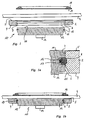
- FIGS. 1 to 1b serves as a mounting flange 2 trained ring for attachment the entire arrangement of a glass 4.
- the mounting flange 2 is at its one End face provided with an adhesive layer 5, with whose help he permanently attached to the glass 4 can be as shown in Fig. 1b.
- the extending through the mounting flange 2 therethrough central opening 6 has a substantially cylindrical Inner surface 7 on, in which one extends over the entire circumference extending annular groove 8 is formed.
- the opening 6 expands frustoconically Outside.
- the switch unit 10 consists of a flat cylindrical Switch housing 12, in which a not visible in the figures Proximity switch is housed so that its sensitive to the approach of a body switch surface in the top in Figs. 1 to 1b End face 11 of the switch housing 12 is located.
- the connection 14, with the help of the proximity switch with a circuit electronics can be connected is in Figs. 1 and 1b shown only schematically.
- the switch housing 12 has a cylindrical outer surface 15, whose diameter is only slightly smaller is the diameter of the inner surface 7 of the mounting flange 2.
- a cylindrical outer surface 15 In the outer surface 15 is a about the entire circumference extending annular groove 16 is formed, for receiving an O-ring 17 made of elastically deformable Material serves.
- Fig. 1a has the Ring groove 16 in the axial direction a height that is slightly smaller than the thickness of the O-ring 17, so that this under slight compression between those in Figs. 1 to 1b upper or lower groove side wall are clamped can.
- the depth of the annular groove 16 perpendicular to the outer surface 15 is dimensioned so that at the bottom surface of the Ring groove 16 fitting O-ring to about a quarter to a third of its thickness over the outer surface 15 radially protrudes outwards.
- the axial distance of the axial center of the annular groove 8 of the coated with adhesive 5 face of the mounting flange 2, as shown in FIG. 1a, is slightly smaller as the axial distance of the axial center of the annular groove 16 from the end face 11. This has the consequence that then, if you the switch housing 12 with the mounting flange. 2 assembled by insertion in the axial direction, without in that the mounting flange 2 is glued to the glass pane 4 is, the end face 11 slightly above the adhesive layer 5 protrudes in the axial direction.
- the mounting flange 2 is present the insertion of the switch housing 12 to the glass 4 glued. This allows the switch housing 12 are not advanced so far in the axial direction, as shown in Fig. 1a. This way it stays the O-ring 17 is deformed somewhat elastically in the way that he directed a glass pane 4 toward Relative force between the mounting flange 2 and the Switch housing 12 generates. Together with the adhesion, the between the appropriately ground and polished end face 11 of the switch housing 12 and the glass sheet 4 is formed in the assembled state, this results in an excellent holder of the switch housing 12 on the mounting flange 2 and the glass 4. At least the air layer between the glass pane 4 and the end face 11 kept so thin that no condensation and when using a capacitive proximity switch no impairment of sensitivity entry.
- a Cover and hand guide ring 18 is provided with the Help an adhesive layer 19 on the glass 4 permanently can be attached and its inner diameter is chosen so that when approaching a body, for example, a human hand a switching operation triggering, in the end face 11 of the switch housing 12 arranged switch surface encloses and visually and tactile clearly marked.
- an annular Mounting flange 21 includes, with the switch housing 12th in a conventional manner, for example, connected by gluing is.
- the mounting flange 21 also made in one piece with the switch housing 12 or be connected in any other way.
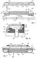
- the mounting flange has several continuous in the axial direction Mounting holes 22, of which in section the Fig. 2 and 2a only one is shown.
- the Plate 4 ' on whose in Figs. 2 and 2a upper side the switch housing 12 to be mounted, points here a through opening 23 for the connection 14. Furthermore, in the plate 4 'more continuous Mounting openings 24 are provided, of which in Figs. 2 and 2a also only one is visible. Between the Plate 4 'facing end face of the mounting flange 21 and the plate 4 ', a sealing ring 25 is provided, the mounting holes 22 and mounting holes 24 corresponding has through openings 26.
- FIGS. 2 and 2a are both here the switch housing 12 and the mounting flange 21st cylindrical outer surfaces 15 and 29, in each case one circumferentially circumferential annular groove 16 and 30 for receiving an O-ring 17 or 31 is incorporated.
- the relative dimensions of the annular grooves 16 and 30 in relation to the O-rings 17, 31 are the same as above has been described with reference to Figs. 1 to 1b.
- annular Covering flange 33 is provided, whose continuous Opening 35 two substantially cylindrical inner wall sections 36, 37, whose different diameters each slightly smaller than the outer diameter the cylindrical outer surface 15 of the switch housing 12 and the cylindrical outer surface 29 of the mounting flange 21 are.
- each of these cylindrical Inner wall sections 36, 37 is one in the circumferential direction circumferential annular groove 38 and 39 incorporated, the how one particularly takes the Fig. 2a, such an axial Has position that they are in the assembled state of Ring groove 16 of the switch housing 12 and the annular groove 30th the mounting flange 21 is opposite and for receiving of the annular grooves projecting part of the relevant O-rings 17 and 31, respectively.
- the offset axially opposite annular grooves be that the O-rings 17, 31 in the assembled state remain elastically deformed and thus one to the plate 4 ' to exert directed force on the cover 33.
- Double switch unit 40 is provided, which is a flat cylindrical Switch housing 41 includes, in the two End faces 42, 47 each one approaching Button a corresponding switch arranged is.
- this double switch unit 40 both from the top in Fig. 3 side of Glass plate 4 as well as from the bottom in this figure Pressed "back" ago.
- the substantially cylindrical outer surface of the switch housing 41 here has two with an axial distance arranged, extending in the circumferential direction annular grooves on, in each of which an O-ring 43, 44 housed of which the O-ring 43 is for connecting the Switch housing 41 in the same way with a on the glass 4 glued mounting flange 45 serves as described with reference to Figs. 1 to 1b was, and of which the O-ring 44 according to the Embodiment of Fig. 2 and 2a for holding a Cover flange 46 is provided.
- the synonymous with this Embodiment existing connections, with their help the two housed in the switch housing 41 proximity switch be connected to the associated electronics, are led out laterally and for the sake of simplicity not shown in Fig. 3.
- Double switch unit 40 opposite surface of the Glass 4 a cover and hand guide ring 18 with Help an adhesive layer 19 are glued.
Landscapes
- Engineering & Computer Science (AREA)
- Power Engineering (AREA)
- Switch Cases, Indication, And Locking (AREA)
- Details Of Connecting Devices For Male And Female Coupling (AREA)
- Steering Controls (AREA)
Description
Die Erfindung betrifft eine Verbindungs- und Montageanordnung für eine flache Schaltereinheit.The invention relates to a connection and mounting arrangement for a flat switch unit.
Unter einer "flachen Schaltereinheit" sollen hier insbesondere Näherungsschalter verstanden werden, die in einem flachzylindrischen Gehäuse so angeordnet sind, daß die Annäherung eines Körpers, beispielsweise einer menschlichen Hand an die eine der Stirnseiten des flachen Zylinders zur Auslösung eines Schaltvorganges führt. Dabei kann die die Annäherung eines Körpers feststellende Elektronik in dem flachzylindrischen Schaltergehäuse untergebracht sein, so daß dieses Gehäuse dann nur noch Anschlüsse für die Stromversorgung und die Abgabe des Schaltsignales aufweisen muß.Under a "flat switch unit" should here in particular Proximity switches are understood in one flat cylindrical housing are arranged so that the Approaching a body, such as a human Hand to the one of the end faces of the flat cylinder leads to the triggering of a switching process. there can the the approaching of a body Electronics housed in the flat cylindrical switch housing be, so that this case then only Connections for the power supply and the delivery of the Must have switching signals.
Ein wichtiges Einsatzgebiet derartiger Schalter sind Verkehrsmittel wie z.B. Omnibusse und Straßenbahnen, bei denen die Fahrgäste durch Berühren einer entsprechend vorgegebenen und gekennzeichneten Fläche an der FahrzeugAußenseite die Tür öffnen bzw. an einer Oberfläche im Fahrzeuginneren ein Vorbereitungssignal erzeugen, das dazu führt, daß an der nächsten Haltestelle die betreffende Tür geöffnet wird, wenn der Fahrer des Fahrzeuges ein allgemeines Freigabesignal erzeugt.An important application of such switches are means of transport such as. Buses and trams, at the passengers by touching a corresponding predetermined and marked area on the vehicle outside open the door or on a surface in the vehicle interior generate a preparation signal that leads that at the next stop the concerned Door is opened when the driver of the vehicle enters Generated general enable signal.
Bei den genannten aber auch anderen Anwendungsfällen ist es häufig wünschenswert, derartige Schalter auf der von der Bedienungsperson abgewandten Seite einer Glasplatte so zu montieren, daß die näherungsempfindliche Schaltfläche mit der Glasplatte in Berührung steht, oder alternativ hierzu den flachen Schalter auf einer ihn tragenden im allgemeinen ebenen Fläche aus beliebigem Material so zu montieren, daß er nur geringfügig über diese Fläche vorsteht.In the mentioned but also other applications is It is often desirable to have such switches on the the operator facing away from a glass plate mount so that the proximity-sensitive button is in contact with the glass plate, or alternatively For this purpose, the flat switch on a carrying him generally flat surface of any material so to assemble that he only slightly above this area protrudes.
Damit in beiden Fällen ein und dasselbe Schaltergehäuse verwendet werden kann, ist es zweckmäßig, für die Hinterglas-Montage zusätzlich zum Schaltergehäuse einen geeigneten Montage-Ringflansch vorzusehen, während bei der Montage auf einer festen Oberfläche ein Abdeck-Ringflansch verwendet werden muß, der die näherungsempfindliche Fläche umgrenzt und einen kontinuierlichen Übergang zu der den Schalter tragenden Oberfläche schafft.So that in both cases one and the same switch housing can be used, it is appropriate for the rear glass mounting in addition to the switch housing a suitable Provide mounting ring flange, while in the Mounting on a solid surface a cover ring flange must be used, which is the approximate surface bounded and a continuous transition to the Creates a switch-bearing surface.
Aus der DE 42 08 087 C, ist eine Verbindungs-und Montageanordnung bekannt, mit deren Hilfe ein elektro-mechanischer Drucktaster, in einer seinem Durchmesser entsprechenden Bohrung einer Wand dadurch montiert wird, daß ein ihn im wesentlichen umgebender Ringflansch an seiner Außenumfangsfläche eine Nut aufweist, der im eingebauten Zustand eine entsprechende Nut in der Bohrungs-Innenwand des den Drucktaster tragenden Körpers gegenüberliegt. In die beiden Nuten ist ein O-Ring so eingefügt, daß der den Drucktaster tragende Ringflansch in der Bohrung des Körpers gehalten wird.From DE 42 08 087 C, is a Connection and mounting arrangement known, with the help of an electro-mechanical Pushbutton, in a hole of a wall corresponding to its diameter is mounted that a substantially surrounding him annular flange at his Outer peripheral surface has a groove in the installed state, a corresponding Groove in the bore inner wall of the push button bearing body opposite. In the two grooves, an O-ring is inserted so that the push button bearing Ring flange is held in the bore of the body.
Aus der DE 89 02 044 U ist es bekannt, einen Näherungsschalter mit Hilfe einer ihn umgebenden Buchse in der durchgehenden Bohrung einer Wand zu montieren, wobei die Buchse in diese Bohrung eingeschraubt wird und an ihrer Innenumfangsfläche wenigstens eine Nut aufweist, der im zusammengebauten Zustand eine auf der Außenfläche des zylindrischen Näherungsschalters vorgesehene Umfangsnut gegenüberliegt. Die Verbindung zwischen der Montagebuchse und dem Näherungsschalter erfolgt mit Hilfe eines in diese beiden einander gegenüberliegenden Nuten eingefügten O-Rings.From DE 89 02 044 U it is known, a proximity switch using a him mount the surrounding socket in the through hole of a wall, the Bush is screwed into this hole and on its inner peripheral surface has at least one groove in the assembled state one on the Outer surface of the cylindrical proximity switch provided circumferential groove opposite. The connection between the mounting bush and the Proximity switch is made using one in these two opposite each other Grooves inserted O-rings.
In beiden Fällen ist es jedoch erforderlich, die den jeweiligen Schalter tragende Wand mit einerdurchgehenden Bohrung zu versehen, deren Innendurchmesser deutlich größer ist als der Außendurchmesser des Schalters, da die Bohrung jeweils auch noch den Ringflansch bzw. die Halterungsbuchse aufnehmen muß.In both cases, however, it is necessary, the wall carrying the respective switch with to provide a through hole whose inner diameter is significantly larger as the outer diameter of the switch, since the bore also still the Ring flange or the socket must accommodate.
Demgegenüber liegt der Erfindung die Aufgabe zugrunde, eine Verbindungs- und Montageanordnung zu schaffen, bei der es nicht erforderlich ist, in der den Schalter tragenden Wand eine derart große Durchgangsöffnung auszubilden.In contrast, the invention has the object, a connection and To provide mounting arrangement in which it is not necessary in the switch supporting wall to form such a large passage opening.
Zur Lösung dieser Aufgabe sieht die Erfindung die im Anspruch 1 zusammengefaßten Merkmale vor.To solve this problem, the invention provides in the Claim 1 summarized features.
Durch die erfindungsgemäßen Maßnahmen wird eine außerordentlich kostengünstige Möglichkeit geschaffen, zunächst einen Montageflansch auf der einen Seite einer Glasscheibe beispielsweise durch Ankleben zu befestigen und dann das zylindrische Schaltergehäuse von hinten her in diesen Flansch einzuschieben.By the measures according to the invention is an extraordinary cost-effective opportunity created, first a mounting flange on one side of a To attach glass pane by gluing, for example and then the cylindrical switch housing from the rear to insert into this flange.
Durch den vor dem Zusammenbau vorzugsweise in die umlaufende Ringnut des Schaltergehäuses eingesetzten und aus dieser Ringnut vorstehenden O-Ring wird eine durch elastische Verformung bewirkte Schnapp- und Rastverbindung zwischen dem Schaltergehäuse und dem Ringflansch hergestellt, die das Schaltergehäuse im Montageringflansch sicher haltert.By the before the assembly preferably inserted into the circumferential annular groove of the switch housing and from this annular groove projecting O-ring is a through elastic deformation caused snap and snap connection manufactured between the switch housing and the annular flange, the switch housing in the mounting ring flange safely holds.
Es entsteht eine äußerst flache und auch den harten Einsatzbedingungen in Verkehrsmitteln gewachsene Anordnung, die besonders kostengünstig ist.It creates a very flat and also the tough conditions of use in transport Arrangement that is particularly cost-effective is.
Ein weiterer Vorteil ist darin zu sehen, daß der Einbau und Austausch des Schalters bei der Hinterglasmontage ohne das Bohren von Löchern möglich ist. Das übliche Ausstanzen des gesamten Schalterdurchmessers ist bei dieser Montageart nicht erforderlich.Another advantage is the fact that the installation and replacement of the switch during the back glass assembly without drilling holes is possible. The usual punching of the entire switch diameter is not required for this type of mounting.
Weitere vorteilhafte Ausgestaltungen der erfindungsgemäßen Verbindungs- und Montageanordnung sind in den Unteransprüchen niedergelegt. Further advantageous embodiments of the invention Connection and mounting arrangement are in the Dependent claims.
Die Erfindung wird im folgenden anhand von Ausführungsbeispielen unter Bezugnahme auf die Zeichnung beschrieben; in dieser zeigen:
- Fig. 1
- eine auseinandergezogene Schnittdarstellung einer erfindungsgemäßen Verbindungs- und Montageanordnung für die Hinterglas-Montage eines Näherungsschalters,
- Fig. 1a
- in vergrößertem Maßstab ein Detail aus der Darstellung in Fig. 1, wobei das flachzylindrische Schaltergehäuse und der Montageflansch ineinandergeschoben sind, ohne daß der Montageflansch an einer Glasscheibe befestigt ist,
- Fig. 1b
- eine Schnittansicht der Anordnung aus Fig. 1 im zusammengebauten Zustand,
- Fig. 2
- eine der Fig. 1 entsprechende Darstellung einer nicht zur Erfindung gehörenden Verbindungs- und Montageanordnung für eine auf einer ebenen Fläche erfolgenden Montage,
- Fig. 2a
- eine Einzelheit der Anordnung aus Fig. 2 im zusammengebauten Zustand und
- Fig. 3
- eine weitere Ausführungsform, bei der der eine Schalter einer Doppelschaltereinheit hinter Glas montiert und der andere Schalter von der Rückseite her zugänglich ist.
- Fig. 1
- an exploded sectional view of a connecting and mounting arrangement according to the invention for the behind-glass mounting of a proximity switch,
- Fig. 1a
- on an enlarged scale, a detail from the illustration in Figure 1, wherein the flat-cylindrical switch housing and the mounting flange are pushed together without the mounting flange is attached to a glass pane,
- Fig. 1b
- 3 is a sectional view of the arrangement of FIG. 1 in the assembled state,
- Fig. 2
- 1 corresponding representation of a not belonging to the invention connection and mounting arrangement for an assembly taking place on a flat surface,
- Fig. 2a
- a detail of the arrangement of Fig. 2 in the assembled state and
- Fig. 3
- a further embodiment in which one switch of a double switch unit mounted behind glass and the other switch is accessible from the rear side.
Bei der in den Fig. 1 bis 1b dargestellten Ausführungsform
dient ein als Montageflansch 2 ausgebildeter Ring zur Befestigung
der gesamten Anordnung an einer Glasscheibe 4.
Zu diesem Zweck ist der Montageflansch 2 an seiner einen
Stirnfläche mit einer Klebstoffschicht 5 versehen, mit
deren Hilfe er dauerhaft an der Glasscheibe 4 befestigt
werden kann, wie dies in Fig. 1b gezeigt ist.In the embodiment shown in FIGS. 1 to 1b
serves as a
Die sich durch den Montageflansch 2 hindurch erstreckende
zentrale Öffnung 6 weist eine im wesentlichen zylindrische
Innenfläche 7 auf, in der eine sich über den gesamten Umfang
erstreckende Ringnut 8 ausgebildet ist.The extending through the
An der Stirnseite 9, die der mit der Klebstoffschicht 5
beschichteten Stirnseite des Montageflansches 2 gegenüberliegt,
erweitert sich die Öffnung 6 stumpfkegelig nach
außen.At the
Die Schaltereinheit 10 besteht aus einem flachzylindrischen
Schaltergehäuse 12, in dem ein in den Figuren nicht sichtbarer
Näherungsschalter so untergebracht ist, daß seine
für die Annäherung eines Körpers empfindliche Schalterfläche
sich in der in den Fig. 1 bis 1b oben liegenden
Stirnfläche 11 des Schaltergehäuses 12 befindet. Der Anschluß
14, mit dessen Hilfe der Näherungsschalter mit
einer Schaltungselektronik verbunden werden kann, ist in
den Fig. 1 und 1b nur schematisch dargestellt.The
Das Schaltergehäuse 12 weist eine zylindrische Außenfläche
15 auf, deren Durchmesser nur geringfügig kleiner
ist als der Durchmesser der Innenfläche 7 des Montageflansches
2. In der Außenfläche 15 ist eine sich über
den gesamten Umfang erstreckende Ringnut 16 ausgebildet,
die zur Aufnahme eines O-Rings 17 aus elastisch verformbarem
Material dient.The
Wie man insbesondere der Fig. 1a entnimmt, besitzt die
Ringnut 16 in axialer Richtung eine Höhe, die geringfügig
kleiner als die Dicke des O-Ringes 17 ist, so daß dieser
unter leichter Kompression zwischen die in den Fig. 1
bis 1b obere bzw. untere Nut-Seitenwand eingeklemmt werden
kann. Die Tiefe der Ringnut 16 senkrecht zur Außenfläche
15 ist so bemessen, daß der an der Bodenfläche der
Ringnut 16 anliegende O-Ring zu etwa einem Viertel bis
einem Drittel seiner Dicke über die Außenfläche 15 radial
nach außen vorsteht.As can be seen in particular of Fig. 1a, has the
Dieser vorstehende Teil des O-Rings greift, wie insbesondere in der Fig. 1a deutlich sichtbar, im zusammengebauten Zustand in die Ringnut 8 des Montageflansches 2 ein. Dabei sind die Abmessungen der Ringnut 8 an diesen vorstehenen Teil des O-Ringes so angepaßt, daß er sowohl mit dem Boden der Ringnut 8 als auch ihren beiden Seitenwänden in Eingriff steht.This protruding part of the O-ring intervenes, in particular clearly visible in the Fig., In the assembled Condition in the annular groove 8 of the mounting flange 2 a. The dimensions of the annular groove 8 protrude therefrom Part of the O-ring adapted so that it both with the bottom of the annular groove 8 and its two side walls engaged.
Der axiale Abstand der axialen Mitte der Ringnut 8 von
der mit Klebstoff 5 beschichteten Stirnfläche des Montageflansches
2 ist, wie man der Fig. 1a entnimmt, etwas kleiner
als der axiale Abstand der axialen Mitte der Ringnut
16 von der Stirnfläche 11. Dies hat zur Folge, daß dann,
wenn man das Schaltergehäuse 12 mit dem Montageflansch 2
durch Einschieben in axialer Richtung zusammenbaut, ohne
daß der Montageflansch 2 an der Glasscheibe 4 angeklebt
ist, die Stirnfläche 11 geringfügig über die Klebstoffschicht
5 in axialer Richtung vorsteht.The axial distance of the axial center of the annular groove 8 of
the coated with adhesive 5 face of the mounting
Allerdings wird in der Praxis der Montageflansch 2 vor
dem Einschieben des Schaltergehäuses 12 an die Glasscheibe
4 angeklebt. Dadurch kann das Schaltergehäuse
12 nicht so weit in axialer Richtung vorgeschoben werden,
wie dies Fig. 1a zeigt. Auf diese Weise bleibt
der O-Ring 17 ständig etwas elastisch in der Weise verformt,
daß er eine zur Glasscheibe 4 hin gerichtete
Relativkraft zwischen dem Montageflansch 2 und dem
Schaltergehäuse 12 erzeugt. Zusammen mit der Adhäsionskraft,
die zwischen der entsprechend geschliffenen und
polierten Stirnfläche 11 des Schaltergehäuses 12 und
der Glasscheibe 4 im zusammengebauten Zustand entsteht,
ergibt dies eine ausgezeichnete Halterung des Schaltergehäuses
12 am Montageflansch 2 und der Glasscheibe 4.
Zumindest wird die Luftschicht zwischen der Glasscheibe
4 und der Stirnfläche 11 so dünn gehalten, daß keine Kondensatbildung
und bei Verwendung eines kapazitiven Näherungsschalters
keine Beeinträchtigung der Empfindlichkeit
eintritt.However, in practice, the mounting
Auf der dem Montageflansch 2 und der Schaltereinheit
10 gegenüberliegenden Fläche der Glasscheibe 4 ist ein
Abdeck- und Hand-Führungsring 18 vorgesehen, der mit
Hilfe einer Kleberschicht 19 auf der Glasscheibe 4 dauerhaft
befestigt werden kann und dessen Innendurchmesser
so gewählt ist, daß er die bei Annäherung eines Körpers,
beispielsweise einer menschlichen Hand einen Schaltvorgang
auslösende, in der Stirnfläche 11 des Schaltergehäuses
12 angeordnete Schalterfläche umschließt und optisch
und taktil deutlich erkennbar markiert. On the mounting
In den Fig. 2 und 2a ist eine nicht zur Erfindung gehörende Ausführungsform wiedergegeben,
bei der die Schaltereinheit 10' neben dem flachzylindrischen
Schaltergehäuse 12 einen kreisringförmigen
Montageflansch 21 umfaßt, der mit dem Schaltergehäuse 12
auf herkömmliche Weise, beispielsweise durch Kleben verbunden
ist. Alternativ hierzu kann der Montageflansch 21
mit dem Schaltergehäuse 12 auch einstückig ausgeführt
oder in sonstiger Weise verbunden sein.2 and 2a a not belonging to the invention embodiment is shown,
in which the switch unit 10 'in addition to the flat
Der Montageflansch weist mehrere in axialer Richtung durchgehende
Montagelöcher 22 auf, von denen im Schnitt der
Fig. 2 und 2a jeweils nur eines wiedergegeben ist. Die
Platte 4', auf deren in den Fig. 2 und 2a oberen Seite
das Schaltergehäuse 12 montiert werden soll, weist
hier eine durchgehende Öffnung 23 für den Anschluß 14 auf.
Weiterhin sind in der Platte 4' mehrere durchgehende
Montageöffnungen 24 vorgesehen, von denen in den Fig. 2
und 2a ebenfalls nur eine sichtbar ist. Zwischen der der
Platte 4' zugewandten Stirnfläche des Montageflansches
21 und der Platte 4' ist ein Dichtring 25 vorgesehen,
der den Montagelöchern 22 und Montageöffnungen 24 entsprechende
durchgehende Öffnungen 26 besitzt. Im zusammengebauten
Zustand fluchten dann, wenn der Anschluß 14 durch
die Öffnung 23 hindurchragt, die Montagelöcher 22 mit den
Öffnungen 26 und Montageöffnungen 24, so daß durch sie
Befestigungsschrauben 28 hindurchgeführt werden können,
die entweder in ein in die Platte 4' eingearbeitetes Gewinde
(nicht dargestellt) eingreifen oder mit Hilfe einer
(ebenfalls nicht dargestellten) Mutter auf der dem Schaltergehäuse
12 gegenüberliegenden Seite der Platte 4' verschraubt
werden können.The mounting flange has several continuous in the axial direction
Mounting holes 22, of which in section the
Fig. 2 and 2a only one is shown. The
Plate 4 ', on whose in Figs. 2 and 2a upper side
the
Wie man den Fig. 2 und 2a entnimmt, besitzen hier sowohl
das Schaltergehäuse 12 als auch der Montageflansch 21
zylindrische Außenflächen 15 bzw. 29, in die jeweils eine
in Umfangsrichtung umlaufende Ringnut 16 bzw. 30 zur Aufnahme
eines O-Ringes 17 bzw. 31 eingearbeitet ist. Die
relativen Abmessungen der Ringnuten 16 und 30 in Bezug
auf die O-Ringe 17, 31 sind die gleichen, wie dies oben
unter Bezugnahme auf die Fig. 1 bis 1b beschrieben wurde.As can be seen in FIGS. 2 and 2a, they are both here
the
Weiterhin ist bei diesem Ausführungsbeispiel ein ringförmiger
Abdeckflansch 33 vorgesehen, dessen durchgehende
Öffnung 35 zwei im wesentlichen zylindrische Innenwandabschnitte
36, 37 aufweist, deren unterschiedliche Durchmesser
jeweils geringfügig kleiner als der Außendurchmesser
der zylindrischen Außenfläche 15 des Schaltergehäuses
12 bzw. der zylindrischen Außenfläche 29 des Montageflansches
21 sind. In jeden dieser zylindrischen
Innenwandabschnitte 36, 37 ist eine in Umfangsrichtung
umlaufende Ringnut 38 bzw. 39 eingearbeitet, die, wie
man insbesondere der Fig. 2a entnimmt, eine solche axiale
Position besitzt, daß sie im zusammengebauten Zustand der
Ringnut 16 des Schaltergehäuses 12 bzw. der Ringnut 30
des Montageflansches 21 gegenüberliegt und zur Aufnahme
des aus diesen Ringnuten vorstehenden Teils des betreffenden
O-Rings 17 bzw. 31 dient. Auch hier können die
einander gegenüberliegenden Ringnuten axial so versetzt
sein, daß die O-Ringe 17, 31 im zusammengebauten Zustand
elastisch verformt bleiben und somit eine zur Platte 4'
hin gerichtete Kraft auf den Abdeckflansch 33 ausüben.Furthermore, in this embodiment, an
Wie man den Fig. 2 und 2a entnimmt, sind auch hier die
im wesentlichen zylindrischen Innenwandabschnitte 36, 37
zu der Seite hin stumpfkegelig erweitert, von der her
die O-Ringe 17, 31 beim Zusammenbau eintreten, um das
Aufschieben des Abdeckflansches 33 auf das Schaltergehäuse
12 und den Montageflansch 21 zu erleichtern.As can be seen in FIGS. 2 and 2a, here too are the
substantially cylindrical
Bei der in Fig. 3 wiedergegebenen Ausführungsform ist eine
Doppel-Schaltereinheit 40 vorgesehen, die ein flachzylindrisches
Schaltergehäuse 41 umfaßt, in dessen beiden
Stirnflächen 42, 47 jeweils eine auf Annäherung reagierende
Schaltfläche eines entsprechenden Schalters angeordnet
ist. Somit kann diese Doppelschaltereinheit
40 sowohl von der in Fig. 3 oben liegenden Seite der
Glasplatte 4 als auch von der in dieser Figur unten liegenden
"Rückseite" her betätigt werden.In the embodiment shown in Fig. 3 is a
Die im wesentlichen zylindrische Außenfläche des Schaltergehäuses
41 weist hier zwei mit einem axialen Abstand
angeordnete, im Umfangsrichtung verlaufende Ringnuten
auf, in denen jeweils ein O-Ring 43, 44 untergebracht
ist, von denen der O-Ring 43 zur Verbindung des
Schaltergehäuses 41 in der gleichen Weise mit einem
auf die Glasscheibe 4 aufgeklebten Montageflansch 45 dient,
wie dies unter Bezugnahme auf die Fig. 1 bis 1b beschrieben
wurde, und von denen der O-Ring 44 entsprechend dem
Ausführungsbeispiel der Fig. 2 und 2a zur Halterung eines
Abdeckflansches 46 vorgesehen ist. Die auch bei diesem
Ausführungsbeispiel vorhandenen Anschlüsse, mit deren Hilfe
die beiden im Schaltergehäuse 41 untergebrachten Näherungsschalter
mit der zugehörigen Elektronik verbunden werden,
sind seitlich herausgeführt und der Einfachheit halber
in Fig. 3 nicht wiedergegeben.The substantially cylindrical outer surface of the
Auch bei diesem Ausführungsbeispiel kann auf die der
Doppelschaltereinheit 40 gegenüberliegende Fläche der
Glasscheibe 4 ein Abdeck- und Hand-Führungsring 18 mit
Hilfe einer Kleberschicht 19 aufgeklebt werden. Also in this embodiment can on the
Auch bei dem in Fig. 3 gezeigten Ausführungsbeispiel kann
im Berührungsbereich zwischen dem Montageflansch 45 und
dem Abdeckflansch 46 ein gemäß der Erfindung zur Halterung
dienender O-Ring in entsprechenden Nuten vorgesehen
sein.Also in the embodiment shown in Fig. 3 can
in the contact area between the mounting
Claims (2)
- A connecting and assembly arrangement which includes a flat switch unit, in the one flat side of which is disposed the actuating surface of a switch, and an annular flange surrounding the switch unit, wherein the annular flange (2; 45) is in the form of an assembly flange for an assembly fitted at one side on to a surface of a body (4, 4') and has at least one substantially cylindrical inside surface (7) in which there is a groove (8) extending therearound in the peripheral direction, and the switch unit (10; 40) has at least one substantially cylindrical outside surface (15) whose diameter is slightly smaller than the diameter of the inside surface (7) of the annular flange (2; 45) and in which a groove (16) extending therearound in the peripheral direction is also provided and so positioned that in the condition of being fitted together it is approximately in opposite relationship to the groove (8) of the annular flange (2; 45), and wherein an O-ring (17; 43, 44) of elastic material which can be fitted into one of the two grooves before the arrangement is fitted together is of such a thickness that with elastic deformation it can be pressed into the respective groove to such an extent that the switch unit (10; 40) and the annular flange (2; 45) can be pushed axially one into the other for fitting together and when the two grooves in question are in approximately mutually opposite relationship the O-ring (17; 43, 44) extends with at least partial elastic stress relief into the other of the two grooves to such an extent that it connects the switch unit (10; 40) to the annular flange (2; 45), and wherein finally the axial spacing of the axial centre of the annular groove (8) in the annular flange (2) from the end face of the annular flange (2) which in the assembled condition comes to bear against the surface is somewhat smaller than the axial spacing of the axial centre of the annular groove (16) of the switch unit (10) from the end face (11) of the switch unit (10) which in the assembled condition comes to bear against the surface so that in the condition of being fitted together but not assembled to the surface the end face (11) of the switch unit (10) projects slightly beyond the end face of the annular flange (2) which in the assembled condition comes to bear against the surface.
- A connecting and assembly arrangement according to claim 1 characterised in that provided on the switch unit (40) is a further peripherally extending groove for an O-ring (44) which serves for connecting the switch unit (40) to an annular cover flange (46).
Applications Claiming Priority (2)
| Application Number | Priority Date | Filing Date | Title |
|---|---|---|---|
| DE19718807A DE19718807C1 (en) | 1997-05-03 | 1997-05-03 | Connecting and mounting arrangement for flat switch unit with actuating surface in one flat side and annular flange enclosing unit |
| DE19718807 | 1997-05-03 |
Publications (3)
| Publication Number | Publication Date |
|---|---|
| EP0877458A2 EP0877458A2 (en) | 1998-11-11 |
| EP0877458A3 EP0877458A3 (en) | 1999-02-10 |
| EP0877458B1 true EP0877458B1 (en) | 2005-11-23 |
Family
ID=7828582
Family Applications (1)
| Application Number | Title | Priority Date | Filing Date |
|---|---|---|---|
| EP98106624A Expired - Lifetime EP0877458B1 (en) | 1997-05-03 | 1998-04-09 | Connection- and mounting device |
Country Status (2)
| Country | Link |
|---|---|
| EP (1) | EP0877458B1 (en) |
| DE (1) | DE19718807C1 (en) |
Families Citing this family (4)
| Publication number | Priority date | Publication date | Assignee | Title |
|---|---|---|---|---|
| EP2552031A1 (en) * | 2011-07-26 | 2013-01-30 | EAO Holding AG | Door opener switch |
| FR3007156B1 (en) * | 2013-06-14 | 2015-12-25 | Crouzet Automatismes | BUTTON, CONTROL BUTTON ASSEMBLY AND METHOD OF MOUNTING SUCH ASSEMBLY |
| EP3736985A1 (en) | 2019-05-10 | 2020-11-11 | Captron Electronic GmbH | Illuminated switch |
| NL2033532B1 (en) | 2022-11-15 | 2024-05-28 | Ventura Systems C V | Sensor door button being attachable to a window panel of a vehicle door. |
Family Cites Families (4)
| Publication number | Priority date | Publication date | Assignee | Title |
|---|---|---|---|---|
| DE3636575A1 (en) * | 1986-10-28 | 1988-05-05 | Standard Elektrik Lorenz Ag | ROTARY SWITCH |
| DE8902044U1 (en) * | 1989-02-21 | 1989-05-11 | Pepperl & Fuchs Gmbh, 6800 Mannheim | proximity switch |
| DE4202084A1 (en) * | 1992-01-27 | 1993-01-28 | Herbert Mitscherling | Multi-element control panel for electronic switchboard - receives printed circuit board and plug inserts, switches, lights and instruments |
| DE4208087C1 (en) * | 1992-03-13 | 1993-04-29 | K.A. Schmersal Gmbh & Co., 5600 Wuppertal, De | Electromechanical push-button switch for vehicle door - has groove on outer circumference of cylindrical housing for snap-fitting O=ring installed on door or similar |
-
1997
- 1997-05-03 DE DE19718807A patent/DE19718807C1/en not_active Expired - Lifetime
-
1998
- 1998-04-09 EP EP98106624A patent/EP0877458B1/en not_active Expired - Lifetime
Also Published As
| Publication number | Publication date |
|---|---|
| EP0877458A2 (en) | 1998-11-11 |
| EP0877458A3 (en) | 1999-02-10 |
| DE19718807C1 (en) | 1998-09-10 |
Similar Documents
| Publication | Publication Date | Title |
|---|---|---|
| EP0937311B1 (en) | Device for fixing a distance sensor to an automobile | |
| DE602004002232T2 (en) | Electronic device | |
| DE3722069A1 (en) | SIGNAL HORN SWITCHING DEVICE FOR A STEERING WHEEL | |
| EP0749136B1 (en) | Switch for opening a door | |
| WO2001036903A1 (en) | Measuring rope-path sensor | |
| EP0411230B1 (en) | Pressure measuring device | |
| DE202004021354U1 (en) | Device for contacting a first contact partner with a second contact partner e.g. chassis parts of vehicles comprises an electrically non-conducting elastically deformable support having an electrically conducting layer | |
| EP0877458B1 (en) | Connection- and mounting device | |
| DE4116779C2 (en) | Vacuum brake booster | |
| DE4117303A1 (en) | STEERING WHEEL | |
| DE3605388C2 (en) | Electro-hydraulic switching device | |
| DE3803041A1 (en) | DEVICE FOR PRESSURE DISPLAY | |
| DE9113754U1 (en) | Electrical short-stroke push button | |
| DE3437778C2 (en) | ||
| DE19737909B4 (en) | Tactile switch with approach | |
| EP0875972B1 (en) | Device for optical detection of arcing in switchgear | |
| EP1052748A1 (en) | Operating element for mounting on a front panel | |
| EP0604835A1 (en) | Butterfly valve | |
| DE2164652A1 (en) | ELECTRIC SWITCH | |
| DE3220584A1 (en) | Sealing element for a screw connection | |
| DE1916595B2 (en) | ||
| EP0856863A2 (en) | Pivotable actuator for a safety switch | |
| DE4128017C2 (en) | Short stroke push button | |
| DE9400632U1 (en) | counter | |
| AT397012B (en) | ADJUSTMENT DEVICE FOR A DEVICE WITH ELECTRICAL CONTROL DEVICE |
Legal Events
| Date | Code | Title | Description |
|---|---|---|---|
| PUAI | Public reference made under article 153(3) epc to a published international application that has entered the european phase |
Free format text: ORIGINAL CODE: 0009012 |
|
| AK | Designated contracting states |
Kind code of ref document: A2 Designated state(s): FR GB IT |
|
| AX | Request for extension of the european patent |
Free format text: AL;LT;LV;MK;RO;SI |
|
| PUAL | Search report despatched |
Free format text: ORIGINAL CODE: 0009013 |
|
| AK | Designated contracting states |
Kind code of ref document: A3 Designated state(s): AT BE CH CY DE DK ES FI FR GB GR IE IT LI LU MC NL PT SE |
|
| AX | Request for extension of the european patent |
Free format text: AL;LT;LV;MK;RO;SI |
|
| K1C1 | Correction of patent application (title page) published |
Effective date: 19981111 |
|
| RAP3 | Party data changed (applicant data changed or rights of an application transferred) |
Owner name: CAPTRON ELECTRONIC GMBH |
|
| 17P | Request for examination filed |
Effective date: 19990311 |
|
| K1C3 | Correction of patent application (complete document) published |
Effective date: 19981111 |
|
| D17P | Request for examination filed (deleted) | ||
| R17P | Request for examination filed (corrected) |
Effective date: 19990406 |
|
| AKX | Designation fees paid |
Free format text: FR GB IT |
|
| REG | Reference to a national code |
Ref country code: DE Ref legal event code: 8566 |
|
| 17Q | First examination report despatched |
Effective date: 20030509 |
|
| GRAP | Despatch of communication of intention to grant a patent |
Free format text: ORIGINAL CODE: EPIDOSNIGR1 |
|
| GRAS | Grant fee paid |
Free format text: ORIGINAL CODE: EPIDOSNIGR3 |
|
| GRAA | (expected) grant |
Free format text: ORIGINAL CODE: 0009210 |
|
| AK | Designated contracting states |
Kind code of ref document: B1 Designated state(s): FR GB IT |
|
| REG | Reference to a national code |
Ref country code: GB Ref legal event code: FG4D Free format text: NOT ENGLISH |
|
| GBT | Gb: translation of ep patent filed (gb section 77(6)(a)/1977) |
Effective date: 20060107 |
|
| ET | Fr: translation filed | ||
| PLBE | No opposition filed within time limit |
Free format text: ORIGINAL CODE: 0009261 |
|
| STAA | Information on the status of an ep patent application or granted ep patent |
Free format text: STATUS: NO OPPOSITION FILED WITHIN TIME LIMIT |
|
| 26N | No opposition filed |
Effective date: 20060824 |
|
| REG | Reference to a national code |
Ref country code: FR Ref legal event code: PLFP Year of fee payment: 18 |
|
| REG | Reference to a national code |
Ref country code: FR Ref legal event code: PLFP Year of fee payment: 19 |
|
| REG | Reference to a national code |
Ref country code: FR Ref legal event code: PLFP Year of fee payment: 20 |
|
| PGFP | Annual fee paid to national office [announced via postgrant information from national office to epo] |
Ref country code: FR Payment date: 20170424 Year of fee payment: 20 Ref country code: GB Payment date: 20170425 Year of fee payment: 20 |
|
| PGFP | Annual fee paid to national office [announced via postgrant information from national office to epo] |
Ref country code: IT Payment date: 20170407 Year of fee payment: 20 |
|
| REG | Reference to a national code |
Ref country code: GB Ref legal event code: PE20 Expiry date: 20180408 |
|
| PG25 | Lapsed in a contracting state [announced via postgrant information from national office to epo] |
Ref country code: GB Free format text: LAPSE BECAUSE OF EXPIRATION OF PROTECTION Effective date: 20180408 |