EP0877179B1 - Chain guide - Google Patents
Chain guide Download PDFInfo
- Publication number
- EP0877179B1 EP0877179B1 EP98106955A EP98106955A EP0877179B1 EP 0877179 B1 EP0877179 B1 EP 0877179B1 EP 98106955 A EP98106955 A EP 98106955A EP 98106955 A EP98106955 A EP 98106955A EP 0877179 B1 EP0877179 B1 EP 0877179B1
- Authority
- EP
- European Patent Office
- Prior art keywords
- slide rail
- slide
- chain
- portions
- rail according
- Prior art date
- Legal status (The legal status is an assumption and is not a legal conclusion. Google has not performed a legal analysis and makes no representation as to the accuracy of the status listed.)
- Expired - Lifetime
Links
Images
Classifications
-
- F—MECHANICAL ENGINEERING; LIGHTING; HEATING; WEAPONS; BLASTING
- F16—ENGINEERING ELEMENTS AND UNITS; GENERAL MEASURES FOR PRODUCING AND MAINTAINING EFFECTIVE FUNCTIONING OF MACHINES OR INSTALLATIONS; THERMAL INSULATION IN GENERAL
- F16H—GEARING
- F16H7/00—Gearings for conveying rotary motion by endless flexible members
- F16H7/18—Means for guiding or supporting belts, ropes, or chains
-
- F—MECHANICAL ENGINEERING; LIGHTING; HEATING; WEAPONS; BLASTING
- F16—ENGINEERING ELEMENTS AND UNITS; GENERAL MEASURES FOR PRODUCING AND MAINTAINING EFFECTIVE FUNCTIONING OF MACHINES OR INSTALLATIONS; THERMAL INSULATION IN GENERAL
- F16H—GEARING
- F16H7/00—Gearings for conveying rotary motion by endless flexible members
- F16H7/08—Means for varying tension of belts, ropes, or chains
- F16H2007/0802—Actuators for final output members
- F16H2007/0808—Extension coil springs
-
- F—MECHANICAL ENGINEERING; LIGHTING; HEATING; WEAPONS; BLASTING
- F16—ENGINEERING ELEMENTS AND UNITS; GENERAL MEASURES FOR PRODUCING AND MAINTAINING EFFECTIVE FUNCTIONING OF MACHINES OR INSTALLATIONS; THERMAL INSULATION IN GENERAL
- F16H—GEARING
- F16H7/00—Gearings for conveying rotary motion by endless flexible members
- F16H7/08—Means for varying tension of belts, ropes, or chains
- F16H2007/0863—Finally actuated members, e.g. constructional details thereof
- F16H2007/0872—Sliding members
-
- F—MECHANICAL ENGINEERING; LIGHTING; HEATING; WEAPONS; BLASTING
- F16—ENGINEERING ELEMENTS AND UNITS; GENERAL MEASURES FOR PRODUCING AND MAINTAINING EFFECTIVE FUNCTIONING OF MACHINES OR INSTALLATIONS; THERMAL INSULATION IN GENERAL
- F16H—GEARING
- F16H7/00—Gearings for conveying rotary motion by endless flexible members
- F16H7/08—Means for varying tension of belts, ropes, or chains
- F16H7/0829—Means for varying tension of belts, ropes, or chains with vibration damping means
- F16H7/0838—Means for varying tension of belts, ropes, or chains with vibration damping means of the dissipating material type, e.g. elastomeric spring
Definitions
- the invention relates to a slide rail according to the preamble of Claim 1.
- a known sliding block - FR-PS 1 408 575 - comprises a sliding surface that overlaps extends the entire length of said slide rail.
- a generic slide rail is known from EP-A-193802.
- the sliding surface consists of different adjacent segments.
- the object of the invention is this slide rail in terms of weight and Optimize material usage.
- the main advantages achieved with the invention are that the Sliding sections secure a functional chain guide and the cutout Weight and material use reduction contributes.
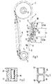
- crankshaft 2 and one of an internal combustion engine 1 Camshaft 3 shown.
- the latter is mounted in a cylinder head, not shown and actuates valves of the internal combustion engine 1.
- chain sprockets 4 and 5 are attached, the one with a chain 6 Form chain drive 7.
- crankshaft 2 rotates clockwise, so that the chain drive 7 at 8 Lasttrum is; the lost drum is labeled 9.
- slide rail 10 On the load strand 8 of the chain drive 7 there is a slide rail 10 which is made of metal, Plastic or the like. Can exist and with a sliding surface 11 made of friction Plastic or rubber is provided.
- the sliding surface 11 comprises two spaced apart Sliding sections 12, 13, between which a cutout 14 is provided.
- the slide rail 10 comprises a carrier 15 heavy-duty polyamide with fiber additives, whereas those on this support 15, namely to the sliding sections 12, 13 attached coverings 16, 17 made of polyamide exist without fiber additives.
- the cutout 14 has a U-shaped shape, and the sliding sections 12, 13 can in Chain running direction - Klr - crowned on the side facing the chain 6 - shape course 6 be executed.
- the carrier 15 has one in the region of the cutout 14 double-T-shaped cross section on - Fig. 3 -, with spaced webs 18, 19 through Ribs 20 - like a lattice girder - are supported.
- the lengths LIGa and LIIGa the Sliding sections 12 and La of the section 14 can be calculated or iterative To be defined.
- the linings 16, 17 are only provided in the area of the sliding sections 12, 13 and work with the carrier 15 via interlocking connections 18, 19, e.g. Dovetail design, together (Fig. 2).
- the carrier 15 is first in Injection molding process made. After that, the Coatings 16, 17 also combined with the carrier 15 by injection molding. This The method is described in detail in DE 37 06 136 C1 and has been described in Proven in practice many times.
Description
Die Erfindung bezieht sich auf eine Gleitschiene nach dem Oberbegriff des Patentantspruchs 1.The invention relates to a slide rail according to the preamble of Claim 1.
Eine bekannte Gleitscheine - FR-PS 1 408 575 - umfaßt eine Gleitfläche, die sich über die gesamte Länge der besagten Gleitschiene erstreckt.A known sliding block - FR-PS 1 408 575 - comprises a sliding surface that overlaps extends the entire length of said slide rail.
Eine gattungsgemäβe Gleitschiene ist aus der EP-A-193802 bekannt. Die Gleitfläche besteht aus verschiedenen aneinander liegenden Segmenten.A generic slide rail is known from EP-A-193802. The sliding surface consists of different adjacent segments.
Aufgabe der Erfindung ist es, diese Gleitschiene bezüglich Gewicht und Werkstoffeinsatz zu optimieren.The object of the invention is this slide rail in terms of weight and Optimize material usage.
Erfindungsgemäß wird diese Aufgabe durch die Merkmale des Patentanspruchs 1 gelöst. Weitere, die Erfindung ausgestaltende Merkmale sind in den nachfolgenden Ansprüchen enthalten.According to the invention, this object is achieved by the features of patent claim 1 solved. Further features embodying the invention are in the following Claims included.
Die mit der Erfindung hauptsächlich erzielten Vorteile sind darin zu sehen, daß die Gleitabschnitte eine funktionsgerechte Kettenführung sichern und der Ausschnitt zur Gewichts- und Werkstoffeinsatz-Reduktion beiträgt.The main advantages achieved with the invention are that the Sliding sections secure a functional chain guide and the cutout Weight and material use reduction contributes.
In der Zeichnung ist ein Ausführungsbeispiel bezeigt, das nachstehend näher bezeichnet ist.In the drawing, an embodiment is shown, which in more detail below is designated.
Es zeigt:
- Fig. 1
- Einen Kettentrieb zwischen einer Kurbelwelle und einer Nockenwelle einer Brennkraftmaschine mit der erfindungsgemäßen Gleitschiene,
- Fig. 2
- einen Schnitt nach der Linie II-II der Fig. 1 in größerem Maßstab,
- Fig. 3
- einen Schnitt nach der Linie III-III der Fig. 1.
- Fig. 1
- A chain drive between a crankshaft and a camshaft of an internal combustion engine with the slide rail according to the invention,
- Fig. 2
- 2 shows a section along the line II-II of FIG. 1 on a larger scale,
- Fig. 3
- a section along the line III-III of Fig. 1st
Von einer Brennkraftmaschine 1 wird lediglich eine Kurbelwelle 2 und eine
Nockenwelle 3 gezeigt. Letztere ist in einem nicht dargstellten Zylinderkopf gelagert
und betätigt Ventile der Brennkraftmaschine 1. An der Kurbelwelle 2 und der
Nockenwelle 3 sind Kettenräder 4 bzw. 5 angebracht, die mit einer Kette 6 einen
Kettentrieb 7 bilden.Only one crankshaft 2 and one of an internal combustion engine 1
Camshaft 3 shown. The latter is mounted in a cylinder head, not shown
and actuates valves of the internal combustion engine 1. On the crankshaft 2 and
Camshaft 3
Die Kurbelwelle 2 dreht sich im Uhrzeigersinn, so daß am Kettentrieb 7 bei 8 das Lasttrum ist; das Lostrum ist mit 9 bezeichnet.The crankshaft 2 rotates clockwise, so that the chain drive 7 at 8 Lasttrum is; the lost drum is labeled 9.
Am Lasttrum 8 des Kettentriebs 7 liegt eine Gleitschiene 10 an, die aus Metall,
Kunststoff oder dgl. bestehen kann und mit einer Gleitfläche 11 aus reibfestem
Kunststoff oder Kautschuk versehen ist. Die Gleitfläche 11 umfaßt zwei beabstandete
Gleitabschnitte 12, 13, zwischen denen ein Ausschnitt 14 vorgesehen ist.On the
Im Ausführungsbeispiel umfaßt die Gleitschiene 10 einen Träger 15 aus
hochbelastbarem Polyamid mit Faserzusätzen, wogegen die an diesem Träger 15,
und zwar an den Gleitabschnitten 12, 13 angebrachte Beläge 16, 17 aus Polyamid
ohne Faserzusätze bestehen.In the exemplary embodiment, the
Der Ausschnitt 14 hat eine U-förmige Gestalt, und die Gleitabschnitte 12, 13 können in
Kettenlaufrichtung - Klr - auf der der Kette 6 zugekehrten Seite ballig - Formverlauf 6
ausgeführt sein. Der Träger 15 weist im Bereich des Ausschnitts 14 einen
doppel-T-förmigen Querschnitt auf - Fig. 3 -, wobei beabstandete Stege 18, 19 durch
Rippen 20 - gitterträgerartig - abgestützt sind. Die Längen LIGa und LIIGa der
Gleitabschnitte 12 sowie La des Ausschnittes 14 können rechnerisch oder iterativ
definiert werden.The
Die Beläge 16, 17 sind lediglich im Bereich der Gleitabschnitte 12, 13 vorgesehen und
arbeiten mit dem Träger 15 über hintereinandergreifende Verbindungen 18, 19, z.B.
Schwalbenschwanzbauart, zusammen (Fig. 2). Dabei wird der Träger 15 zunächst im
Spritzgußverfahren hergestellt. Danach werden in einem weiteren Verfahrensgang die
Beläge 16, 17 ebenfalls im Spritzgußverfahren mit dem Träger 15 vereinigt. Dieses
Verfahren wird in der DE 37 06 136 C1 ausführlich beschrieben und hat sich in der
Praxis vielfach bewährt.The
Claims (6)
- A slide rail for a chain drive of the continuous type, for example between a crankshaft and one or more camshafts, which slide rail consists of a suitable material, such as metal, plastics material or the like, and has a slide face of wear-resistant plastics material or rubber cooperating with the chain, wherein the slide rail (11) comprises two slide portions (12, 13) spaced in the longitudinal direction of the chain, characterized in that the slide rail (11) is provided with an opening (14) between the slide portions.
- A slide rail according to Claim 1, characterized in that the slide rail (11) comprises a support (15) of plastics material on which the slide portions (12, 13) are provided.
- A slide rail according to Claim 1, characterized in that the opening (14) is U-shaped.
- A slide rail according to Claims 1 and 2, characterized in that on the side facing a chain (6) of the chain drive (7) the slide portions (12, 13) consist of wear-resistant material having damping characteristics, such as rubber, elastomers or the like.
- A slide rail according to one or more of the preceding Claims, characterized in that the slide portions (12, 13) are linings (16, 17) cooperating with the support (15) by way of interlocking connexions (21).
- A slide rail according to one or more of the preceding Claims, characterized in that the linings (16, 17) are provided only in the region of the slide portions (12, 13).
Applications Claiming Priority (2)
| Application Number | Priority Date | Filing Date | Title |
|---|---|---|---|
| DE19719732A DE19719732C1 (en) | 1997-05-09 | 1997-05-09 | Slide rail for a chain drive |
| DE19719732 | 1997-05-09 |
Publications (2)
| Publication Number | Publication Date |
|---|---|
| EP0877179A1 EP0877179A1 (en) | 1998-11-11 |
| EP0877179B1 true EP0877179B1 (en) | 2001-08-01 |
Family
ID=7829165
Family Applications (1)
| Application Number | Title | Priority Date | Filing Date |
|---|---|---|---|
| EP98106955A Expired - Lifetime EP0877179B1 (en) | 1997-05-09 | 1998-04-16 | Chain guide |
Country Status (2)
| Country | Link |
|---|---|
| EP (1) | EP0877179B1 (en) |
| DE (2) | DE19719732C1 (en) |
Families Citing this family (9)
| Publication number | Priority date | Publication date | Assignee | Title |
|---|---|---|---|---|
| DE19856705A1 (en) * | 1998-12-09 | 2000-06-21 | Daimler Chrysler Ag | Automotive camshaft chain guide incorporates elastic masses reduces the generation of unwanted noise |
| DE102007026939A1 (en) | 2007-06-12 | 2008-12-24 | Audi Ag | Sliding element for chain drive, is integrally formed, and has sliding surface turned to chain of chain drive, where sliding surface has leading section for leading chain on specific curve |
| DE102014014719A1 (en) | 2014-10-02 | 2016-04-07 | Iwis Motorsysteme Gmbh & Co. Kg | Clamp or guide rail with a continuous retracted sliding lining body |
| DE102014014720A1 (en) | 2014-10-02 | 2016-04-07 | Iwis Motorsysteme Gmbh & Co. Kg | Clamp or guide rail with breakthrough |
| US10495193B2 (en) * | 2014-10-02 | 2019-12-03 | Iwis Motorsysteme Gmbh & Co. Kg | Chain drive having a plurality of sliding elements |
| DE102015008877A1 (en) | 2015-07-08 | 2016-08-04 | Iwis Motorsysteme Gmbh & Co. Kg | Modular sliding or tensioning rail |
| DE102017106049A1 (en) | 2017-03-21 | 2017-05-04 | Iwis Motorsysteme Gmbh & Co. Kg | Clamp or guide rail with two juxtaposed sliding lining bodies |
| DE102017109680A1 (en) * | 2017-05-05 | 2018-11-08 | Iwis Motorsysteme Gmbh & Co. Kg | Elastic guide rail |
| DE102019131314A1 (en) * | 2019-11-20 | 2021-05-20 | Iwis Motorsysteme Gmbh & Co. Kg | Tension or guide rail with an integrated sliding surface |
Family Cites Families (6)
| Publication number | Priority date | Publication date | Assignee | Title |
|---|---|---|---|---|
| US1579681A (en) * | 1924-12-23 | 1926-04-06 | Weller John | Means for transmitting motion |
| GB725984A (en) * | 1952-03-28 | 1955-03-16 | Daimler Benz Ag | Improvements relating to damping devices for limiting oscillation of gear chains |
| FR1408575A (en) * | 1964-09-22 | 1965-08-13 | Morse Chain Co | Damper for chain drives |
| DE3506010A1 (en) * | 1985-02-21 | 1986-08-21 | Feldmühle AG, 4000 Düsseldorf | TENSIONER OR SLIDE RAIL FOR CHAIN DRIVE CHAINS |
| DE3706136C1 (en) * | 1987-02-26 | 1988-09-15 | Porsche Ag | Process for manufacturing a chain tensioner |
| DE19616081C1 (en) * | 1996-04-23 | 1998-01-22 | Contitech Antriebssysteme Gmbh | Belt drive |
-
1997
- 1997-05-09 DE DE19719732A patent/DE19719732C1/en not_active Expired - Fee Related
-
1998
- 1998-04-16 EP EP98106955A patent/EP0877179B1/en not_active Expired - Lifetime
- 1998-04-16 DE DE59801105T patent/DE59801105D1/en not_active Expired - Fee Related
Also Published As
| Publication number | Publication date |
|---|---|
| DE19719732C1 (en) | 1998-11-26 |
| DE59801105D1 (en) | 2001-09-06 |
| EP0877179A1 (en) | 1998-11-11 |
Similar Documents
| Publication | Publication Date | Title |
|---|---|---|
| DE3706136C1 (en) | Process for manufacturing a chain tensioner | |
| EP0856686B1 (en) | Sliding rail for guiding and/or tensioning a chain | |
| EP0987405B1 (en) | Chain drive for internal combustion engine | |
| EP1099827B1 (en) | Chain guide for an internal combustion engine camshaft drive and a method for producing a chain guide | |
| DE102015001334A1 (en) | Articulated chain with friction-reduced chain link back | |
| EP0877179B1 (en) | Chain guide | |
| EP1561968B1 (en) | Tension or guide rail with installation channel | |
| EP3201494B1 (en) | Chain drive having a plurality of sliding elements | |
| DE102014014719A1 (en) | Clamp or guide rail with a continuous retracted sliding lining body | |
| DE102014014720A1 (en) | Clamp or guide rail with breakthrough | |
| DE102015008877A1 (en) | Modular sliding or tensioning rail | |
| DE10107534A1 (en) | Internal combustion engine with a cylinder crankcase | |
| DE10211308A1 (en) | toothed chain | |
| EP1013948A2 (en) | Crankshaft bearing for a combustion engine | |
| EP0778428B1 (en) | Chain guide and slide for motor vehicles | |
| EP2778026A1 (en) | Crawler-track for a ski trail grooming machine | |
| DE3417100C2 (en) | Chain guide for a timing chain to drive a camshaft | |
| DE102010009971A1 (en) | Chain link for use as link of e.g. roller chain in engine, has intermediate part comprising surf surface, where chain link is hydrodynamically supported at tensioning rail by surf surface during sliding chain link over rail by lubricant | |
| DE102017106049A1 (en) | Clamp or guide rail with two juxtaposed sliding lining bodies | |
| DE19905579A1 (en) | Slide rail for guiding or gripping of a chain in e.g. cars has lining insert and insert grip connections | |
| DE102017119821A1 (en) | Clamp or guide rail with channel | |
| DE202017107766U1 (en) | Driver for chain scraper conveyor | |
| DE102016002682A1 (en) | Timing chain with odd number of single lugs | |
| DE102019131314A1 (en) | Tension or guide rail with an integrated sliding surface | |
| DE2747271A1 (en) | CONNECTOR TRACK CHAIN FOR OFF-ROAD VEHICLES |
Legal Events
| Date | Code | Title | Description |
|---|---|---|---|
| PUAI | Public reference made under article 153(3) epc to a published international application that has entered the european phase |
Free format text: ORIGINAL CODE: 0009012 |
|
| AK | Designated contracting states |
Kind code of ref document: A1 Designated state(s): DE FR GB IT |
|
| AX | Request for extension of the european patent |
Free format text: AL;LT;LV;MK;RO;SI |
|
| 17P | Request for examination filed |
Effective date: 19981126 |
|
| AKX | Designation fees paid |
Free format text: DE FR GB IT |
|
| 17Q | First examination report despatched |
Effective date: 20000706 |
|
| GRAG | Despatch of communication of intention to grant |
Free format text: ORIGINAL CODE: EPIDOS AGRA |
|
| GRAG | Despatch of communication of intention to grant |
Free format text: ORIGINAL CODE: EPIDOS AGRA |
|
| GRAH | Despatch of communication of intention to grant a patent |
Free format text: ORIGINAL CODE: EPIDOS IGRA |
|
| ITF | It: translation for a ep patent filed |
Owner name: DE DOMINICIS & MAYER S.R.L. |
|
| GRAH | Despatch of communication of intention to grant a patent |
Free format text: ORIGINAL CODE: EPIDOS IGRA |
|
| GRAA | (expected) grant |
Free format text: ORIGINAL CODE: 0009210 |
|
| AK | Designated contracting states |
Kind code of ref document: B1 Designated state(s): DE FR GB IT |
|
| REF | Corresponds to: |
Ref document number: 59801105 Country of ref document: DE Date of ref document: 20010906 |
|
| GBT | Gb: translation of ep patent filed (gb section 77(6)(a)/1977) |
Effective date: 20010904 |
|
| ET | Fr: translation filed | ||
| REG | Reference to a national code |
Ref country code: GB Ref legal event code: IF02 |
|
| PG25 | Lapsed in a contracting state [announced via postgrant information from national office to epo] |
Ref country code: GB Free format text: LAPSE BECAUSE OF NON-PAYMENT OF DUE FEES Effective date: 20020416 |
|
| PLBE | No opposition filed within time limit |
Free format text: ORIGINAL CODE: 0009261 |
|
| STAA | Information on the status of an ep patent application or granted ep patent |
Free format text: STATUS: NO OPPOSITION FILED WITHIN TIME LIMIT |
|
| 26N | No opposition filed | ||
| PG25 | Lapsed in a contracting state [announced via postgrant information from national office to epo] |
Ref country code: DE Free format text: LAPSE BECAUSE OF NON-PAYMENT OF DUE FEES Effective date: 20021101 |
|
| GBPC | Gb: european patent ceased through non-payment of renewal fee |
Effective date: 20020416 |
|
| PG25 | Lapsed in a contracting state [announced via postgrant information from national office to epo] |
Ref country code: FR Free format text: LAPSE BECAUSE OF NON-PAYMENT OF DUE FEES Effective date: 20021231 |
|
| REG | Reference to a national code |
Ref country code: FR Ref legal event code: ST |
|
| PG25 | Lapsed in a contracting state [announced via postgrant information from national office to epo] |
Ref country code: IT Free format text: LAPSE BECAUSE OF NON-PAYMENT OF DUE FEES;WARNING: LAPSES OF ITALIAN PATENTS WITH EFFECTIVE DATE BEFORE 2007 MAY HAVE OCCURRED AT ANY TIME BEFORE 2007. THE CORRECT EFFECTIVE DATE MAY BE DIFFERENT FROM THE ONE RECORDED. Effective date: 20050416 |