EP0876249B1 - Verfahren zur herstellung von hülsen aus kartonverbundmaterial und vorrichtung zur durchführung des verfahrens - Google Patents
Verfahren zur herstellung von hülsen aus kartonverbundmaterial und vorrichtung zur durchführung des verfahrens Download PDFInfo
- Publication number
- EP0876249B1 EP0876249B1 EP97902229A EP97902229A EP0876249B1 EP 0876249 B1 EP0876249 B1 EP 0876249B1 EP 97902229 A EP97902229 A EP 97902229A EP 97902229 A EP97902229 A EP 97902229A EP 0876249 B1 EP0876249 B1 EP 0876249B1
- Authority
- EP
- European Patent Office
- Prior art keywords
- layer
- web
- winding
- mandrel
- longitudinal edge
- Prior art date
- Legal status (The legal status is an assumption and is not a legal conclusion. Google has not performed a legal analysis and makes no representation as to the accuracy of the status listed.)
- Expired - Lifetime
Links
- 239000002131 composite material Substances 0.000 title claims abstract description 23
- 239000011111 cardboard Substances 0.000 title claims abstract description 19
- 238000000034 method Methods 0.000 title claims abstract description 18
- 238000004519 manufacturing process Methods 0.000 title claims description 8
- 230000008569 process Effects 0.000 title abstract description 5
- 229920000642 polymer Polymers 0.000 claims abstract description 27
- 229910052736 halogen Inorganic materials 0.000 claims abstract description 16
- 150000002367 halogens Chemical class 0.000 claims abstract description 16
- 238000003466 welding Methods 0.000 claims abstract description 7
- 238000004804 winding Methods 0.000 claims description 34
- 238000010438 heat treatment Methods 0.000 claims description 6
- 239000011087 paperboard Substances 0.000 claims description 4
- 238000011144 upstream manufacturing Methods 0.000 claims description 4
- 230000004888 barrier function Effects 0.000 claims description 3
- 238000007639 printing Methods 0.000 claims description 3
- 238000002844 melting Methods 0.000 claims 2
- 230000008018 melting Effects 0.000 claims 2
- 238000000576 coating method Methods 0.000 abstract description 2
- 239000000123 paper Substances 0.000 description 12
- 230000005855 radiation Effects 0.000 description 9
- XAGFODPZIPBFFR-UHFFFAOYSA-N aluminium Chemical compound [Al] XAGFODPZIPBFFR-UHFFFAOYSA-N 0.000 description 6
- 229910052782 aluminium Inorganic materials 0.000 description 6
- 239000011888 foil Substances 0.000 description 6
- 229920001169 thermoplastic Polymers 0.000 description 5
- 239000004416 thermosoftening plastic Substances 0.000 description 5
- 239000000155 melt Substances 0.000 description 4
- 238000009792 diffusion process Methods 0.000 description 3
- 239000007788 liquid Substances 0.000 description 3
- 241000209035 Ilex Species 0.000 description 2
- 230000006872 improvement Effects 0.000 description 2
- 238000007789 sealing Methods 0.000 description 2
- 241000512668 Eunectes Species 0.000 description 1
- -1 Polypropylene Polymers 0.000 description 1
- 239000004743 Polypropylene Substances 0.000 description 1
- 230000015572 biosynthetic process Effects 0.000 description 1
- 239000011248 coating agent Substances 0.000 description 1
- 150000001875 compounds Chemical class 0.000 description 1
- 239000004020 conductor Substances 0.000 description 1
- 238000001816 cooling Methods 0.000 description 1
- 238000005520 cutting process Methods 0.000 description 1
- 230000032798 delamination Effects 0.000 description 1
- 230000000694 effects Effects 0.000 description 1
- 238000005265 energy consumption Methods 0.000 description 1
- 238000005338 heat storage Methods 0.000 description 1
- 239000012528 membrane Substances 0.000 description 1
- 239000000203 mixture Substances 0.000 description 1
- 238000004806 packaging method and process Methods 0.000 description 1
- 239000004033 plastic Substances 0.000 description 1
- 239000002985 plastic film Substances 0.000 description 1
- 229920006255 plastic film Polymers 0.000 description 1
- 229920001155 polypropylene Polymers 0.000 description 1
- 230000009467 reduction Effects 0.000 description 1
- 230000001105 regulatory effect Effects 0.000 description 1
- 238000003860 storage Methods 0.000 description 1
- 230000008961 swelling Effects 0.000 description 1
- 238000010792 warming Methods 0.000 description 1
Images


Classifications
-
- B—PERFORMING OPERATIONS; TRANSPORTING
- B29—WORKING OF PLASTICS; WORKING OF SUBSTANCES IN A PLASTIC STATE IN GENERAL
- B29C—SHAPING OR JOINING OF PLASTICS; SHAPING OF MATERIAL IN A PLASTIC STATE, NOT OTHERWISE PROVIDED FOR; AFTER-TREATMENT OF THE SHAPED PRODUCTS, e.g. REPAIRING
- B29C65/00—Joining or sealing of preformed parts, e.g. welding of plastics materials; Apparatus therefor
- B29C65/02—Joining or sealing of preformed parts, e.g. welding of plastics materials; Apparatus therefor by heating, with or without pressure
- B29C65/14—Joining or sealing of preformed parts, e.g. welding of plastics materials; Apparatus therefor by heating, with or without pressure using wave energy, i.e. electromagnetic radiation, or particle radiation
-
- B—PERFORMING OPERATIONS; TRANSPORTING
- B29—WORKING OF PLASTICS; WORKING OF SUBSTANCES IN A PLASTIC STATE IN GENERAL
- B29C—SHAPING OR JOINING OF PLASTICS; SHAPING OF MATERIAL IN A PLASTIC STATE, NOT OTHERWISE PROVIDED FOR; AFTER-TREATMENT OF THE SHAPED PRODUCTS, e.g. REPAIRING
- B29C53/00—Shaping by bending, folding, twisting, straightening or flattening; Apparatus therefor
- B29C53/56—Winding and joining, e.g. winding spirally
- B29C53/58—Winding and joining, e.g. winding spirally helically
-
- B—PERFORMING OPERATIONS; TRANSPORTING
- B29—WORKING OF PLASTICS; WORKING OF SUBSTANCES IN A PLASTIC STATE IN GENERAL
- B29C—SHAPING OR JOINING OF PLASTICS; SHAPING OF MATERIAL IN A PLASTIC STATE, NOT OTHERWISE PROVIDED FOR; AFTER-TREATMENT OF THE SHAPED PRODUCTS, e.g. REPAIRING
- B29C65/00—Joining or sealing of preformed parts, e.g. welding of plastics materials; Apparatus therefor
- B29C65/02—Joining or sealing of preformed parts, e.g. welding of plastics materials; Apparatus therefor by heating, with or without pressure
- B29C65/14—Joining or sealing of preformed parts, e.g. welding of plastics materials; Apparatus therefor by heating, with or without pressure using wave energy, i.e. electromagnetic radiation, or particle radiation
- B29C65/1429—Joining or sealing of preformed parts, e.g. welding of plastics materials; Apparatus therefor by heating, with or without pressure using wave energy, i.e. electromagnetic radiation, or particle radiation characterised by the way of heating the interface
- B29C65/1432—Joining or sealing of preformed parts, e.g. welding of plastics materials; Apparatus therefor by heating, with or without pressure using wave energy, i.e. electromagnetic radiation, or particle radiation characterised by the way of heating the interface direct heating of the surfaces to be joined
-
- B—PERFORMING OPERATIONS; TRANSPORTING
- B29—WORKING OF PLASTICS; WORKING OF SUBSTANCES IN A PLASTIC STATE IN GENERAL
- B29C—SHAPING OR JOINING OF PLASTICS; SHAPING OF MATERIAL IN A PLASTIC STATE, NOT OTHERWISE PROVIDED FOR; AFTER-TREATMENT OF THE SHAPED PRODUCTS, e.g. REPAIRING
- B29C65/00—Joining or sealing of preformed parts, e.g. welding of plastics materials; Apparatus therefor
- B29C65/02—Joining or sealing of preformed parts, e.g. welding of plastics materials; Apparatus therefor by heating, with or without pressure
- B29C65/14—Joining or sealing of preformed parts, e.g. welding of plastics materials; Apparatus therefor by heating, with or without pressure using wave energy, i.e. electromagnetic radiation, or particle radiation
- B29C65/1429—Joining or sealing of preformed parts, e.g. welding of plastics materials; Apparatus therefor by heating, with or without pressure using wave energy, i.e. electromagnetic radiation, or particle radiation characterised by the way of heating the interface
- B29C65/1454—Joining or sealing of preformed parts, e.g. welding of plastics materials; Apparatus therefor by heating, with or without pressure using wave energy, i.e. electromagnetic radiation, or particle radiation characterised by the way of heating the interface scanning at least one of the parts to be joined
- B29C65/1458—Joining or sealing of preformed parts, e.g. welding of plastics materials; Apparatus therefor by heating, with or without pressure using wave energy, i.e. electromagnetic radiation, or particle radiation characterised by the way of heating the interface scanning at least one of the parts to be joined once, i.e. contour welding
-
- B—PERFORMING OPERATIONS; TRANSPORTING
- B29—WORKING OF PLASTICS; WORKING OF SUBSTANCES IN A PLASTIC STATE IN GENERAL
- B29C—SHAPING OR JOINING OF PLASTICS; SHAPING OF MATERIAL IN A PLASTIC STATE, NOT OTHERWISE PROVIDED FOR; AFTER-TREATMENT OF THE SHAPED PRODUCTS, e.g. REPAIRING
- B29C65/00—Joining or sealing of preformed parts, e.g. welding of plastics materials; Apparatus therefor
- B29C65/02—Joining or sealing of preformed parts, e.g. welding of plastics materials; Apparatus therefor by heating, with or without pressure
- B29C65/14—Joining or sealing of preformed parts, e.g. welding of plastics materials; Apparatus therefor by heating, with or without pressure using wave energy, i.e. electromagnetic radiation, or particle radiation
- B29C65/1477—Joining or sealing of preformed parts, e.g. welding of plastics materials; Apparatus therefor by heating, with or without pressure using wave energy, i.e. electromagnetic radiation, or particle radiation making use of an absorber or impact modifier
- B29C65/1483—Joining or sealing of preformed parts, e.g. welding of plastics materials; Apparatus therefor by heating, with or without pressure using wave energy, i.e. electromagnetic radiation, or particle radiation making use of an absorber or impact modifier coated on the article
-
- B—PERFORMING OPERATIONS; TRANSPORTING
- B29—WORKING OF PLASTICS; WORKING OF SUBSTANCES IN A PLASTIC STATE IN GENERAL
- B29C—SHAPING OR JOINING OF PLASTICS; SHAPING OF MATERIAL IN A PLASTIC STATE, NOT OTHERWISE PROVIDED FOR; AFTER-TREATMENT OF THE SHAPED PRODUCTS, e.g. REPAIRING
- B29C65/00—Joining or sealing of preformed parts, e.g. welding of plastics materials; Apparatus therefor
- B29C65/48—Joining or sealing of preformed parts, e.g. welding of plastics materials; Apparatus therefor using adhesives, i.e. using supplementary joining material; solvent bonding
- B29C65/52—Joining or sealing of preformed parts, e.g. welding of plastics materials; Apparatus therefor using adhesives, i.e. using supplementary joining material; solvent bonding characterised by the way of applying the adhesive
-
- B—PERFORMING OPERATIONS; TRANSPORTING
- B29—WORKING OF PLASTICS; WORKING OF SUBSTANCES IN A PLASTIC STATE IN GENERAL
- B29C—SHAPING OR JOINING OF PLASTICS; SHAPING OF MATERIAL IN A PLASTIC STATE, NOT OTHERWISE PROVIDED FOR; AFTER-TREATMENT OF THE SHAPED PRODUCTS, e.g. REPAIRING
- B29C66/00—General aspects of processes or apparatus for joining preformed parts
- B29C66/01—General aspects dealing with the joint area or with the area to be joined
- B29C66/05—Particular design of joint configurations
- B29C66/10—Particular design of joint configurations particular design of the joint cross-sections
- B29C66/11—Joint cross-sections comprising a single joint-segment, i.e. one of the parts to be joined comprising a single joint-segment in the joint cross-section
- B29C66/112—Single lapped joints
-
- B—PERFORMING OPERATIONS; TRANSPORTING
- B29—WORKING OF PLASTICS; WORKING OF SUBSTANCES IN A PLASTIC STATE IN GENERAL
- B29C—SHAPING OR JOINING OF PLASTICS; SHAPING OF MATERIAL IN A PLASTIC STATE, NOT OTHERWISE PROVIDED FOR; AFTER-TREATMENT OF THE SHAPED PRODUCTS, e.g. REPAIRING
- B29C66/00—General aspects of processes or apparatus for joining preformed parts
- B29C66/01—General aspects dealing with the joint area or with the area to be joined
- B29C66/05—Particular design of joint configurations
- B29C66/10—Particular design of joint configurations particular design of the joint cross-sections
- B29C66/13—Single flanged joints; Fin-type joints; Single hem joints; Edge joints; Interpenetrating fingered joints; Other specific particular designs of joint cross-sections not provided for in groups B29C66/11 - B29C66/12
- B29C66/135—Single hemmed joints, i.e. one of the parts to be joined being hemmed in the joint area
-
- B—PERFORMING OPERATIONS; TRANSPORTING
- B29—WORKING OF PLASTICS; WORKING OF SUBSTANCES IN A PLASTIC STATE IN GENERAL
- B29C—SHAPING OR JOINING OF PLASTICS; SHAPING OF MATERIAL IN A PLASTIC STATE, NOT OTHERWISE PROVIDED FOR; AFTER-TREATMENT OF THE SHAPED PRODUCTS, e.g. REPAIRING
- B29C66/00—General aspects of processes or apparatus for joining preformed parts
- B29C66/40—General aspects of joining substantially flat articles, e.g. plates, sheets or web-like materials; Making flat seams in tubular or hollow articles; Joining single elements to substantially flat surfaces
- B29C66/41—Joining substantially flat articles ; Making flat seams in tubular or hollow articles
- B29C66/43—Joining a relatively small portion of the surface of said articles
- B29C66/432—Joining a relatively small portion of the surface of said articles for making tubular articles or closed loops, e.g. by joining several sheets ; for making hollow articles or hollow preforms
- B29C66/4322—Joining a relatively small portion of the surface of said articles for making tubular articles or closed loops, e.g. by joining several sheets ; for making hollow articles or hollow preforms by joining a single sheet to itself
-
- B—PERFORMING OPERATIONS; TRANSPORTING
- B29—WORKING OF PLASTICS; WORKING OF SUBSTANCES IN A PLASTIC STATE IN GENERAL
- B29C—SHAPING OR JOINING OF PLASTICS; SHAPING OF MATERIAL IN A PLASTIC STATE, NOT OTHERWISE PROVIDED FOR; AFTER-TREATMENT OF THE SHAPED PRODUCTS, e.g. REPAIRING
- B29C66/00—General aspects of processes or apparatus for joining preformed parts
- B29C66/40—General aspects of joining substantially flat articles, e.g. plates, sheets or web-like materials; Making flat seams in tubular or hollow articles; Joining single elements to substantially flat surfaces
- B29C66/41—Joining substantially flat articles ; Making flat seams in tubular or hollow articles
- B29C66/43—Joining a relatively small portion of the surface of said articles
- B29C66/432—Joining a relatively small portion of the surface of said articles for making tubular articles or closed loops, e.g. by joining several sheets ; for making hollow articles or hollow preforms
- B29C66/4329—Joining a relatively small portion of the surface of said articles for making tubular articles or closed loops, e.g. by joining several sheets ; for making hollow articles or hollow preforms the joint lines being transversal but non-orthogonal with respect to the axis of said tubular articles, i.e. being oblique
-
- B—PERFORMING OPERATIONS; TRANSPORTING
- B29—WORKING OF PLASTICS; WORKING OF SUBSTANCES IN A PLASTIC STATE IN GENERAL
- B29C—SHAPING OR JOINING OF PLASTICS; SHAPING OF MATERIAL IN A PLASTIC STATE, NOT OTHERWISE PROVIDED FOR; AFTER-TREATMENT OF THE SHAPED PRODUCTS, e.g. REPAIRING
- B29C66/00—General aspects of processes or apparatus for joining preformed parts
- B29C66/70—General aspects of processes or apparatus for joining preformed parts characterised by the composition, physical properties or the structure of the material of the parts to be joined; Joining with non-plastics material
- B29C66/72—General aspects of processes or apparatus for joining preformed parts characterised by the composition, physical properties or the structure of the material of the parts to be joined; Joining with non-plastics material characterised by the structure of the material of the parts to be joined
- B29C66/723—General aspects of processes or apparatus for joining preformed parts characterised by the composition, physical properties or the structure of the material of the parts to be joined; Joining with non-plastics material characterised by the structure of the material of the parts to be joined being multi-layered
- B29C66/7232—General aspects of processes or apparatus for joining preformed parts characterised by the composition, physical properties or the structure of the material of the parts to be joined; Joining with non-plastics material characterised by the structure of the material of the parts to be joined being multi-layered comprising a non-plastics layer
- B29C66/72321—General aspects of processes or apparatus for joining preformed parts characterised by the composition, physical properties or the structure of the material of the parts to be joined; Joining with non-plastics material characterised by the structure of the material of the parts to be joined being multi-layered comprising a non-plastics layer consisting of metals or their alloys
-
- B—PERFORMING OPERATIONS; TRANSPORTING
- B29—WORKING OF PLASTICS; WORKING OF SUBSTANCES IN A PLASTIC STATE IN GENERAL
- B29C—SHAPING OR JOINING OF PLASTICS; SHAPING OF MATERIAL IN A PLASTIC STATE, NOT OTHERWISE PROVIDED FOR; AFTER-TREATMENT OF THE SHAPED PRODUCTS, e.g. REPAIRING
- B29C66/00—General aspects of processes or apparatus for joining preformed parts
- B29C66/70—General aspects of processes or apparatus for joining preformed parts characterised by the composition, physical properties or the structure of the material of the parts to be joined; Joining with non-plastics material
- B29C66/72—General aspects of processes or apparatus for joining preformed parts characterised by the composition, physical properties or the structure of the material of the parts to be joined; Joining with non-plastics material characterised by the structure of the material of the parts to be joined
- B29C66/723—General aspects of processes or apparatus for joining preformed parts characterised by the composition, physical properties or the structure of the material of the parts to be joined; Joining with non-plastics material characterised by the structure of the material of the parts to be joined being multi-layered
- B29C66/7232—General aspects of processes or apparatus for joining preformed parts characterised by the composition, physical properties or the structure of the material of the parts to be joined; Joining with non-plastics material characterised by the structure of the material of the parts to be joined being multi-layered comprising a non-plastics layer
- B29C66/72327—General aspects of processes or apparatus for joining preformed parts characterised by the composition, physical properties or the structure of the material of the parts to be joined; Joining with non-plastics material characterised by the structure of the material of the parts to be joined being multi-layered comprising a non-plastics layer consisting of natural products or their composites, not provided for in B29C66/72321 - B29C66/72324
- B29C66/72328—Paper
-
- B—PERFORMING OPERATIONS; TRANSPORTING
- B29—WORKING OF PLASTICS; WORKING OF SUBSTANCES IN A PLASTIC STATE IN GENERAL
- B29C—SHAPING OR JOINING OF PLASTICS; SHAPING OF MATERIAL IN A PLASTIC STATE, NOT OTHERWISE PROVIDED FOR; AFTER-TREATMENT OF THE SHAPED PRODUCTS, e.g. REPAIRING
- B29C66/00—General aspects of processes or apparatus for joining preformed parts
- B29C66/70—General aspects of processes or apparatus for joining preformed parts characterised by the composition, physical properties or the structure of the material of the parts to be joined; Joining with non-plastics material
- B29C66/72—General aspects of processes or apparatus for joining preformed parts characterised by the composition, physical properties or the structure of the material of the parts to be joined; Joining with non-plastics material characterised by the structure of the material of the parts to be joined
- B29C66/723—General aspects of processes or apparatus for joining preformed parts characterised by the composition, physical properties or the structure of the material of the parts to be joined; Joining with non-plastics material characterised by the structure of the material of the parts to be joined being multi-layered
- B29C66/7234—General aspects of processes or apparatus for joining preformed parts characterised by the composition, physical properties or the structure of the material of the parts to be joined; Joining with non-plastics material characterised by the structure of the material of the parts to be joined being multi-layered comprising a barrier layer
-
- B—PERFORMING OPERATIONS; TRANSPORTING
- B29—WORKING OF PLASTICS; WORKING OF SUBSTANCES IN A PLASTIC STATE IN GENERAL
- B29C—SHAPING OR JOINING OF PLASTICS; SHAPING OF MATERIAL IN A PLASTIC STATE, NOT OTHERWISE PROVIDED FOR; AFTER-TREATMENT OF THE SHAPED PRODUCTS, e.g. REPAIRING
- B29C66/00—General aspects of processes or apparatus for joining preformed parts
- B29C66/80—General aspects of machine operations or constructions and parts thereof
- B29C66/83—General aspects of machine operations or constructions and parts thereof characterised by the movement of the joining or pressing tools
- B29C66/834—General aspects of machine operations or constructions and parts thereof characterised by the movement of the joining or pressing tools moving with the parts to be joined
- B29C66/8341—Roller, cylinder or drum types; Band or belt types; Ball types
- B29C66/83411—Roller, cylinder or drum types
-
- B—PERFORMING OPERATIONS; TRANSPORTING
- B31—MAKING ARTICLES OF PAPER, CARDBOARD OR MATERIAL WORKED IN A MANNER ANALOGOUS TO PAPER; WORKING PAPER, CARDBOARD OR MATERIAL WORKED IN A MANNER ANALOGOUS TO PAPER
- B31C—MAKING WOUND ARTICLES, e.g. WOUND TUBES, OF PAPER, CARDBOARD OR MATERIAL WORKED IN A MANNER ANALOGOUS TO PAPER
- B31C3/00—Making tubes or pipes by feeding obliquely to the winding mandrel centre line
-
- B—PERFORMING OPERATIONS; TRANSPORTING
- B29—WORKING OF PLASTICS; WORKING OF SUBSTANCES IN A PLASTIC STATE IN GENERAL
- B29C—SHAPING OR JOINING OF PLASTICS; SHAPING OF MATERIAL IN A PLASTIC STATE, NOT OTHERWISE PROVIDED FOR; AFTER-TREATMENT OF THE SHAPED PRODUCTS, e.g. REPAIRING
- B29C65/00—Joining or sealing of preformed parts, e.g. welding of plastics materials; Apparatus therefor
- B29C65/02—Joining or sealing of preformed parts, e.g. welding of plastics materials; Apparatus therefor by heating, with or without pressure
- B29C65/14—Joining or sealing of preformed parts, e.g. welding of plastics materials; Apparatus therefor by heating, with or without pressure using wave energy, i.e. electromagnetic radiation, or particle radiation
- B29C65/1403—Joining or sealing of preformed parts, e.g. welding of plastics materials; Apparatus therefor by heating, with or without pressure using wave energy, i.e. electromagnetic radiation, or particle radiation characterised by the type of electromagnetic or particle radiation
- B29C65/1412—Infrared [IR] radiation
-
- B—PERFORMING OPERATIONS; TRANSPORTING
- B29—WORKING OF PLASTICS; WORKING OF SUBSTANCES IN A PLASTIC STATE IN GENERAL
- B29C—SHAPING OR JOINING OF PLASTICS; SHAPING OF MATERIAL IN A PLASTIC STATE, NOT OTHERWISE PROVIDED FOR; AFTER-TREATMENT OF THE SHAPED PRODUCTS, e.g. REPAIRING
- B29C65/00—Joining or sealing of preformed parts, e.g. welding of plastics materials; Apparatus therefor
- B29C65/02—Joining or sealing of preformed parts, e.g. welding of plastics materials; Apparatus therefor by heating, with or without pressure
- B29C65/14—Joining or sealing of preformed parts, e.g. welding of plastics materials; Apparatus therefor by heating, with or without pressure using wave energy, i.e. electromagnetic radiation, or particle radiation
- B29C65/1429—Joining or sealing of preformed parts, e.g. welding of plastics materials; Apparatus therefor by heating, with or without pressure using wave energy, i.e. electromagnetic radiation, or particle radiation characterised by the way of heating the interface
- B29C65/1445—Joining or sealing of preformed parts, e.g. welding of plastics materials; Apparatus therefor by heating, with or without pressure using wave energy, i.e. electromagnetic radiation, or particle radiation characterised by the way of heating the interface heating both sides of the joint
-
- B—PERFORMING OPERATIONS; TRANSPORTING
- B29—WORKING OF PLASTICS; WORKING OF SUBSTANCES IN A PLASTIC STATE IN GENERAL
- B29C—SHAPING OR JOINING OF PLASTICS; SHAPING OF MATERIAL IN A PLASTIC STATE, NOT OTHERWISE PROVIDED FOR; AFTER-TREATMENT OF THE SHAPED PRODUCTS, e.g. REPAIRING
- B29C65/00—Joining or sealing of preformed parts, e.g. welding of plastics materials; Apparatus therefor
- B29C65/48—Joining or sealing of preformed parts, e.g. welding of plastics materials; Apparatus therefor using adhesives, i.e. using supplementary joining material; solvent bonding
- B29C65/52—Joining or sealing of preformed parts, e.g. welding of plastics materials; Apparatus therefor using adhesives, i.e. using supplementary joining material; solvent bonding characterised by the way of applying the adhesive
- B29C65/522—Joining or sealing of preformed parts, e.g. welding of plastics materials; Apparatus therefor using adhesives, i.e. using supplementary joining material; solvent bonding characterised by the way of applying the adhesive by spraying, e.g. by flame spraying
-
- B—PERFORMING OPERATIONS; TRANSPORTING
- B29—WORKING OF PLASTICS; WORKING OF SUBSTANCES IN A PLASTIC STATE IN GENERAL
- B29C—SHAPING OR JOINING OF PLASTICS; SHAPING OF MATERIAL IN A PLASTIC STATE, NOT OTHERWISE PROVIDED FOR; AFTER-TREATMENT OF THE SHAPED PRODUCTS, e.g. REPAIRING
- B29C65/00—Joining or sealing of preformed parts, e.g. welding of plastics materials; Apparatus therefor
- B29C65/48—Joining or sealing of preformed parts, e.g. welding of plastics materials; Apparatus therefor using adhesives, i.e. using supplementary joining material; solvent bonding
- B29C65/52—Joining or sealing of preformed parts, e.g. welding of plastics materials; Apparatus therefor using adhesives, i.e. using supplementary joining material; solvent bonding characterised by the way of applying the adhesive
- B29C65/526—Joining or sealing of preformed parts, e.g. welding of plastics materials; Apparatus therefor using adhesives, i.e. using supplementary joining material; solvent bonding characterised by the way of applying the adhesive by printing or by transfer from the surfaces of elements carrying the adhesive, e.g. using brushes, pads, rollers, stencils or silk screens
-
- B—PERFORMING OPERATIONS; TRANSPORTING
- B29—WORKING OF PLASTICS; WORKING OF SUBSTANCES IN A PLASTIC STATE IN GENERAL
- B29K—INDEXING SCHEME ASSOCIATED WITH SUBCLASSES B29B, B29C OR B29D, RELATING TO MOULDING MATERIALS OR TO MATERIALS FOR MOULDS, REINFORCEMENTS, FILLERS OR PREFORMED PARTS, e.g. INSERTS
- B29K2995/00—Properties of moulding materials, reinforcements, fillers, preformed parts or moulds
- B29K2995/0037—Other properties
- B29K2995/0065—Permeability to gases
- B29K2995/0067—Permeability to gases non-permeable
-
- B—PERFORMING OPERATIONS; TRANSPORTING
- B29—WORKING OF PLASTICS; WORKING OF SUBSTANCES IN A PLASTIC STATE IN GENERAL
- B29K—INDEXING SCHEME ASSOCIATED WITH SUBCLASSES B29B, B29C OR B29D, RELATING TO MOULDING MATERIALS OR TO MATERIALS FOR MOULDS, REINFORCEMENTS, FILLERS OR PREFORMED PARTS, e.g. INSERTS
- B29K2995/00—Properties of moulding materials, reinforcements, fillers, preformed parts or moulds
- B29K2995/0037—Other properties
- B29K2995/0068—Permeability to liquids; Adsorption
- B29K2995/0069—Permeability to liquids; Adsorption non-permeable
-
- B—PERFORMING OPERATIONS; TRANSPORTING
- B29—WORKING OF PLASTICS; WORKING OF SUBSTANCES IN A PLASTIC STATE IN GENERAL
- B29L—INDEXING SCHEME ASSOCIATED WITH SUBCLASS B29C, RELATING TO PARTICULAR ARTICLES
- B29L2031/00—Other particular articles
- B29L2031/712—Containers; Packaging elements or accessories, Packages
- B29L2031/717—Cans, tins
Definitions
- the invention relates to a method with the features of Preamble of claim 1 and a device for Execution of the method with the features of the generic term of claim 5.
- a method and an apparatus of this type are described in EP 0 113 160.
- Cardboard composite boxes usually consist of a sleeve made of multilayer composite, one on one end the base and a lid. On the lid side is for liquid and aroma-tight version a sealing membrane sealed.
- the composition of the composite material depends on the product and the given strength requirements.
- a layer of paper with a metallic inside Barrier layer usually an aluminum foil is arranged, which in turn is laminated with a polymer layer is.
- a polymer layer is laminated with a polymer layer is.
- this sleeve another, usually thicker cardboard layer, the so-called Schrenz, arranged and finally on this one arranged paper web forming the label.
- These pods are designed as winding cores of a helical shape endlessly manufactured Winding tube can be cut to length.
- the composite material runs during the manufacture of a winding tube as an endless path under one of the pitch of the helical Corresponding angle on a winding Winding mandrel.
- a longitudinal edge of the endless web becomes an edge strip with the edge strip underneath the one already on the mandrel Section of the endless web glued.
- Such a winding tube meets increased gas tightness requirements Not.
- the durability of the compound can also suffers humid atmosphere.
- the reason is that the outside and the inside longitudinal edge has an open cut surface form, so that diffusion processes over the cut surfaces through the paper or cardboard layer can take place.
- The is neither gas nor pressure tight. Diffusing moisture can lead to Swelling of the paper or cardboard and for delamination come.
- thermoplastics or thermoplastic coated composite materials to combine focused heat radiation, creating a better energy balance is achieved.
- cardboard boxes known (US 4 156 626)
- the radiation focus is on aligned the polymer layer.
- the Cutting edge covered by a plastic film (EP 0 437 847).
- the composite material consists of a cardboard or Paper layer, an aluminum barrier layer and one thermoplastic film on the other hand.
- the thermoplastic Foil protrudes over the cut edge of the composite material and is placed around this edge and on the opposite side connected to the composite material.
- the point-focused IR radiation is focused on the aligned thermoplastic coating of the composite material, to melt this. After flipping the protruding film, the heat is given off to the film and should be sealed with the composite material.
- the composite material on the warming area with a light absorbing dark To coat strips. This procedure becomes special It was important that the foil and the aluminum layer not before being switched over by the radiation source being affected.
- Claim 1 Based on a procedure based on the generic term of Claim 1 is the object of the invention, a flawless, sharply defined weld seam with simultaneous Reduction of the necessary for the welding process To achieve energy.
- a further improvement in the energy yield or saving in energy and a better concentration at the same time the heat supplied to the weld area then when the endless path at least on the Halogen light facing side at least within the heating edge stripes with a light-absorbing Layer is provided.
- This light absorbing layer can be of any width the width of the weld seam must be applied. This will convert the light energy into thermal energy additionally improved in the area of the weld.
- the light-absorbing layer is preferably one dark, preferably black, trace of color. This therefore bothers not because they later through the outer cardboard layer is covered.
- the invention further relates to a device with the Features of the preamble of claim 5 for manufacture of winding tubes.
- a device stands out according to the invention in that the heating device a focused parallel to the undeformed longitudinal edge, is a linear halogen light source, the halogen light source is arranged above the incoming continuous path.
- a device for applying in front of the mandrel a dark trace of color on the top of the tapered Endless web is arranged. Instead of course you can Endless web already on the occasion of their manufacture be provided with such a trace of color.
- the device also has, as in the prior art known, at least one device for the final Winding up a cardboard web on the winding tube.
- Each according to strength requirements can also be two or more Cardboard webs are wound up on the outside.
- the sleeve 1 shows the cross section of the wall of a sleeve 1 a cardboard composite box on a greatly enlarged scale shown.
- the sleeve 1 can be a circular, oval or more or less rectangular cross-section with rounded Have corners. One then speaks of round or non-round Cans.
- the layer structure of the wall of the sleeve 1 aligns depends essentially on the type of product and the required stability.
- the Sleeve 1 from the inside to the outside a gas and liquid tight Inner layer 2 and three successive layers of cardboard 4, 5 and 6 and an outer layer of paper or plastic sheeting 7, the latter being printed or printable is and forms a label.
- the sleeve 1 according to 1 is produced by winding from an endless web 3, so that, for example, the inner layer 2 there are helically adjacent tracks 3, that overlap in area 8.
- One is Longitudinal edge of the web 3 to the double layer to form the inner layer 9 and the outer layer 10 folded outwards and with the undeformed edge strip 11 of the neighboring one Position of the web 3 connected so that the cut surfaces 12, 13 of the two layers of web 3 are covered.
- the inner layer 2 consists of a outer paper layer 14, one adjoining it inwards metallic layer 15, e.g. from one Aluminum foil, and an inner layer 16 a polymer, e.g. Polypropylene.
- This polymer layer 16 fulfills on the one hand when filling food food hygiene requirements, on the other hand them in conjunction with the metallic layer 15 for the necessary liquid and gas tightness.
- the web 3 forming the inner layer 2 is as with Described with reference to Figure 1, in the overlap area one longitudinal edge folded over to the double layer and the there lying polymer layers 16 for formation a gas and liquid-tight seam 17 thermally welded.
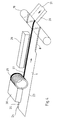
- FIG. 3 are the essential parts of a device shown for the manufacture of the winding tube 1 according to FIG.
- the device has a winding mandrel 18. Of the one side of the mandrel runs through the inner layer 2 forming endless web 3 to that of one on a reel stored coil is withdrawn. From the other side of the The cardboard layers 4, 5 and 6 become the winding mandrel and the continuous webs forming the outer paper layer 7 fed, with only two endless webs 20, 21 indicated are. These endless tracks are already overlapping each other fed to the mandrel 18.
- the endless tracks 3, 20, 21 run with respect to the axis of the mandrel 18 under the Helix angle of the helical to be generated Winding sleeve 22 too.
- the winding technique as such is known (e.g. US 3,716,435), which is why the explanation of Details can be dispensed with.
- the continuous web 3 forming the inner layer 2 is at its in the drawing, the front longitudinal edge 23 upwards folded to double layer 8, while the opposite Longitudinal edge 24 remains undeformed.
- a halogen spotlight 26 is arranged, its light radiation is linearly focused on the edge strip 25.
- This halogen light is in the endless web 3 forming Composite material converted into heat, so that at the The bottom polymer layer melts. she runs on the mandrel 18 on the double layer 8 of the already there filed section of the endless web, so that the heated and melted polymer layer on the Underside of the edge strip 25 with the top Polymer layer of the double layer 8 on the opposite Longitudinal edge 23 welded.
- the heat supply is limited largely on the edge strip 24 and thus on the Welded or sealed seam.
- the temperature can be checked Control the use of the halogen lamp 26 very well, so that also a quick cooling of the seam at further winding process takes place. It can therefore be high web speeds in the manufacture of the drive endless winding tube 22. From this endless The sleeve for the can is then cut to length.
- a dark, e.g. black color trace 27 applied (Fig. 4), which is approximately the width of the edge strip 25 corresponds or is narrower. This will also the concentration of heat on the edge strips 25 supports.
- This color track 27 can with a Halogen lamp 26 upstream sprayer or one Printing unit 28 with a printing roller 29 and an ink fountain 30 are applied to the edge strip 25.
Landscapes
- Engineering & Computer Science (AREA)
- Mechanical Engineering (AREA)
- Physics & Mathematics (AREA)
- Health & Medical Sciences (AREA)
- Electromagnetism (AREA)
- Toxicology (AREA)
- Chemical & Material Sciences (AREA)
- Composite Materials (AREA)
- Laminated Bodies (AREA)
- Making Paper Articles (AREA)
Abstract
Description
- Figur 1
- einen Längsschnitt durch die Wandung der Hülse einer Kartonverbunddose;
- Figur 2
- das Detail II in Figur 1 in vergrößertem Maßstab;
- Figur 3
- eine schematische perspektivische Darstellung einer Vorrichtung zur Herstellung einer spiralig gewickelten Hülse;
- Figur 4
- eine schematische Darstellung einer abgewandelten Ausführungsform der Vorrichtung nach Figur 3.
Claims (7)
- Verfahren zur Herstellung der Hülse (1) von gasdichten Dosen aus Verbundmaterial, die von außen nach innen wenigstens eine Papier- oder Kartonschicht (4,5,6), eine metallische Sperrschicht und eine diese abdeckende, dem Füllgut zugewandte Polymerschicht (2) aufweist, indem eine Endlosbahn (3) aus dem Verbundmaterial an einer Längskante (8) zu einem doppellagigen Randstreifen (9, 10) umgelegt, die Endlosbahn (3) auf einem Randstreifen entlang der gegenüberliegenden Längskante (24) unter Aufschmelzen der Polymerschicht erhitzt, und anschließend auf einem Dorn (18) schraubenförmig zur Bildung eines Wickelrohrs (22) aufgewickelt wird, wobei der erhitzte Randstreifen (25) auf die außenseitige Polymerschicht des doppellagigen Randstreifens eines auf dem Dorn bereits abgelegten Bahnabschnitts überlappend aufläuft und mit diesem durch Verschweißen der Polymerschichten miteinander verbunden wird und anschließend wenigstens eine weitere Papier- oder Kartonschicht (20, 21) auf die Außenseite überlappend aufgelegt und randseitig verklebt wird, dadurch gekennzeichnet, daß der Randstreifen (25) von der die spätere Außenseite der Wickelhülse (21) bildenden Seite her mittels parallel zu der ihn begrenzenden Längskante linienförmig fokussiertem Halogenlicht (26) erhitzt wird.
- Verfahren nach Anspruch 1, dadurch gekennzeichnet, daß die Endlosbahn (3) zumindest auf der dem Halogenlicht (26) zugekehrten Seite wenigstens innerhalb des zu erhitzenden Randstreifens (25) mit einer lichtabsorbierenden Schicht (27) versehen wird.
- Verfahren nach Anspruch 1 oder 2, dadurch gekennzeichnet, daß die lichtabsorbierende Schicht (27) auf einer der Breite der Schweißnaht entsprechenden Breite aufgebracht wird.
- Verfahren nach Anspruch 2 oder 3, dadurch gekennzeichnet, daß als lichtabsorbierende Schicht eine dunkle, vorzugsweise schwarze Farbspur (27) aufgebracht wird.
- Vorrichtung zur Durchführung des Verfahrens nach einem der Ansprüche 1 bis 4 mit einem Wickeldorn (18), dem eine Endlosbahn aus dem Verbundmaterial mittels einer Wickeleinrichtung unter dem Steigungswinkel der schraubenförmigen Wickelhülse (1) zugeführt wird, einer vor dem Wickeldorn (18) angeordneten Einrichtung zum Umlegen der Endlosbahn zu einem doppellagigen Randstreifen (8) entlang der dem Wickeldorn zugekehrten Längskante und einer vor der Auflaufstelle der Endlosbahn (3) auf den Wickeldorn (18) angeordneten Heizeinrichtung (26) zum Aufschmelzen der Polymerschicht auf einem Randstreifen (25) entlang der gegenüberliegenden, unverformten Längskante (24) der Endlosbahn, dadurch gekennzeichnet, daß die Heizeinrichtung eine parallel zu der unverformten Längskante (24) fokussierte, linienförmige Halogenlichtquelle (26) ist, dieoberhalb der zulaufenden Endlosbahn (3) angeordnet ist.
- Vorrichtung nach Anspruch 5, dadurch gekennzeichnet, daß vor dem Wickeldorn (18) eine Einrichtung (27) zum Aufbringen einer lichtabsorbierenden Schicht, z.B. einer dunklen Farbspur, auf der Oberseite der zulaufenden Endlosbahn angeordnet ist.
- Vorrichtung nach Anspruch 6, dadurch gekennzeichnet, daß die Einrichtung ein Sprühgerät oder Druckaggregat (27) ist.
Applications Claiming Priority (3)
| Application Number | Priority Date | Filing Date | Title |
|---|---|---|---|
| DE19602892 | 1996-01-27 | ||
| DE19602892A DE19602892A1 (de) | 1996-01-27 | 1996-01-27 | Verfahren zur Herstellung von Wickelhülsen aus Kartonverbundmaterial, Vorrichtung zur Durchführung des Verfahrens und hierbei verwendetes Kartonverbundmaterial |
| PCT/EP1997/000349 WO1997027041A2 (de) | 1996-01-27 | 1997-01-27 | Verfahren zur herstellung von hülsen aus kartonverbundmaterial, vorrichtung zur durchführung des verfahrens und hierbei verwendetes verbundmaterial |
Publications (2)
| Publication Number | Publication Date |
|---|---|
| EP0876249A2 EP0876249A2 (de) | 1998-11-11 |
| EP0876249B1 true EP0876249B1 (de) | 2001-08-01 |
Family
ID=7783825
Family Applications (1)
| Application Number | Title | Priority Date | Filing Date |
|---|---|---|---|
| EP97902229A Expired - Lifetime EP0876249B1 (de) | 1996-01-27 | 1997-01-27 | Verfahren zur herstellung von hülsen aus kartonverbundmaterial und vorrichtung zur durchführung des verfahrens |
Country Status (5)
| Country | Link |
|---|---|
| US (1) | US6077377A (de) |
| EP (1) | EP0876249B1 (de) |
| CN (1) | CN1072103C (de) |
| DE (2) | DE19602892A1 (de) |
| WO (1) | WO1997027041A2 (de) |
Families Citing this family (9)
| Publication number | Priority date | Publication date | Assignee | Title |
|---|---|---|---|---|
| US20040056006A1 (en) * | 1998-10-01 | 2004-03-25 | The Welding Institute | Welding method |
| DE19850143B4 (de) * | 1998-10-30 | 2004-05-13 | Advanced Photonics Technologies Ag | Verfahren zum Auflaminieren eines Klebebandes auf einen elastischen Profilkörper |
| US6620278B1 (en) * | 2000-04-18 | 2003-09-16 | Nelson Irrigation Corporation | Drip tape manufacturing process |
| AU2002225716A1 (en) | 2000-11-10 | 2002-05-21 | Gentex Corporation | Visibly transparent dyes for through-transmission laser welding |
| US6752893B2 (en) * | 2001-09-28 | 2004-06-22 | Gentex Corporation | Rimless spectacles and method for making the same |
| US7201963B2 (en) * | 2002-01-15 | 2007-04-10 | Gentex Corporation | Pre-processed workpiece having a surface deposition of absorber dye rendering the workpiece weld-enabled |
| FI20020671A7 (fi) * | 2002-04-09 | 2003-10-10 | Stora Enso Oyj | Menetelmä ja laitteisto kartongista valmistettavan tuotteen muovaamiseen |
| US20040163725A1 (en) * | 2003-02-24 | 2004-08-26 | Pierce Peter D. | Substrate for core and tubewinding |
| GB2455340A (en) * | 2007-12-07 | 2009-06-10 | Lamina Dielectrics Ltd | Laser bonding during cable sheath formation |
Family Cites Families (27)
| Publication number | Priority date | Publication date | Assignee | Title |
|---|---|---|---|---|
| US2915952A (en) * | 1959-12-08 | Apparatus for forming containers | ||
| US2145636A (en) * | 1936-03-20 | 1939-01-31 | Riverside Company | Apparatus for manufacturing treansparent cellulosic tubes |
| US2358455A (en) * | 1939-12-06 | 1944-09-19 | Harold E Hallman | Radiant heat seal |
| BE553197A (de) * | 1956-01-03 | 1900-01-01 | ||
| DE1104315B (de) * | 1958-09-11 | 1961-04-06 | Jagenberg Werke Ag | Behaeltermantel mit feuchtigkeitsdichter Auskleidung sowie Verfahren und Vorrichtungzu seiner Herstellung |
| US3183802A (en) * | 1961-05-01 | 1965-05-18 | Reynolds Metals Co | Container and method and apparatus for making the same or the like |
| US3189702A (en) * | 1962-08-15 | 1965-06-15 | Minnesota Mining & Mfg | Package and method of making |
| US3574031A (en) * | 1967-03-24 | 1971-04-06 | Heller William C Jun | Method of heat welding thermoplastic bodies using a stratum of susceptor material |
| US3549451A (en) * | 1968-03-06 | 1970-12-22 | Emanuel Kugler | Method of manufacturing satchel bottom bags |
| DE1778422A1 (de) * | 1968-04-27 | 1971-10-07 | Klebetechnik Gmbh | Vorrichtung zum thermischen Schrumpfen oder Verschweissen einer Kunststoff-Folie |
| US3555976A (en) * | 1969-01-14 | 1971-01-19 | Int Paper Co | Method and apparatus for producing spiral wound container |
| FR2071401A5 (de) * | 1969-12-29 | 1971-09-17 | Biancamaria Joseph | |
| US3673033A (en) * | 1970-02-02 | 1972-06-27 | Sweethart Plastics Inc | Method for making disposable plastic bucket |
| US3716435A (en) * | 1970-11-16 | 1973-02-13 | American Can Co | Method of making a container body |
| DE2157951A1 (de) * | 1971-11-23 | 1973-05-30 | Messer Griesheim Gmbh | Trennschweissverfahren fuer thermoplastenfolien und vorrichtung zur durchfuehrung des verfahrens |
| DE2313120C3 (de) * | 1973-03-16 | 1979-01-04 | Hoesch Werke Ag, 4600 Dortmund | Verfahren und Vorrichtung zum Verbinden der Ränder von Dacheindeckungsbahnen |
| DD129756A1 (de) * | 1976-12-03 | 1978-02-08 | Werner Fritzsche | Vorrichtung zum schweissen thermoplastischer werkstuecke |
| US4156626A (en) * | 1977-07-18 | 1979-05-29 | Souder James J | Method and apparatus for selectively heating discrete areas of surfaces with radiant energy |
| US4243454A (en) * | 1978-07-14 | 1981-01-06 | Fafco, Inc. | Solar heating panel forming apparatus and method |
| EP0113160B1 (de) * | 1982-12-03 | 1987-07-15 | Ajinomoto Co., Inc. | Kanne aus plastischen Materialien |
| US4540392A (en) * | 1983-12-23 | 1985-09-10 | International Paper Company | Method and apparatus to seal coated paperboard materials |
| SE446175B (sv) * | 1985-01-25 | 1986-08-18 | Tetra Pak Int | Material till forpackningsbehallare samt sett att framstella materialet |
| DE3742027A1 (de) * | 1987-12-11 | 1989-06-22 | Varta Batterie | Isolationshuelse fuer galvanische primaerelemente |
| SE465214B (sv) * | 1990-01-16 | 1991-08-12 | Tetra Pak Holdings Sa | Saett att uppvaerma del av loepande materialbana |
| DE9107254U1 (de) * | 1990-06-01 | 1991-08-14 | Mauser-Werke GmbH, 50321 Brühl | Aus gewickeltem und verklebtem Kraftpapier bestehende formstabile Pappkörper und Vorrichtung zu deren Herstellung |
| DE9102388U1 (de) * | 1991-02-28 | 1991-05-16 | Philippine GmbH & Co Technische Kunststoffe KG, 5420 Lahnstein | Vorrichtung zum Verbinden von Polyurethanbahnen |
| US5840147A (en) * | 1995-06-07 | 1998-11-24 | Edison Welding Institute | Plastic joining method |
-
1996
- 1996-01-27 DE DE19602892A patent/DE19602892A1/de not_active Withdrawn
-
1997
- 1997-01-27 DE DE59704191T patent/DE59704191D1/de not_active Expired - Lifetime
- 1997-01-27 EP EP97902229A patent/EP0876249B1/de not_active Expired - Lifetime
- 1997-01-27 CN CN97191891A patent/CN1072103C/zh not_active Expired - Fee Related
- 1997-01-27 WO PCT/EP1997/000349 patent/WO1997027041A2/de not_active Ceased
-
1998
- 1998-01-27 US US09/117,267 patent/US6077377A/en not_active Expired - Fee Related
Also Published As
| Publication number | Publication date |
|---|---|
| US6077377A (en) | 2000-06-20 |
| DE59704191D1 (de) | 2001-09-06 |
| WO1997027041A3 (de) | 1998-02-26 |
| CN1072103C (zh) | 2001-10-03 |
| DE19602892A1 (de) | 1997-07-31 |
| CN1209769A (zh) | 1999-03-03 |
| EP0876249A2 (de) | 1998-11-11 |
| WO1997027041A2 (de) | 1997-07-31 |
Similar Documents
| Publication | Publication Date | Title |
|---|---|---|
| DE60006465T2 (de) | Verfahren zur Herstellung rohrförmiger Verbundbehälter | |
| DE69823391T2 (de) | Verpackungsbehälter zum kalt-lagern von flüssigen nahrungsmitteln sowie verfahren zum herstellen dieses behälters | |
| DE69819572T2 (de) | Rohrförmiger Behälter und Verfahren und Vorrichtung zu dessen Herstellung | |
| DE2925440A1 (de) | Mehrwandiger beutel sowie verfahren und vorrichtung zur herstellung eines mehrwandigen beutels | |
| EP0204137B1 (de) | Verfahren zur Herstellung einer Packung für Flüssigkeiten mit Kantenschutz und Vorrichtung zur Durchführung des Verfahrens | |
| DE4126557A1 (de) | Ultraschallschweissen bei der herstellung von beuteln | |
| EP0114398A2 (de) | Zusammendrückbarer Laminattubenbehälter | |
| DE1436866A1 (de) | Verfahren und Vorrichtung zur Durchfuehrung des Verfahrens zur Herstellung eines mehrschichtigen,beschichteten Rohres | |
| DE69403568T2 (de) | Verfahren zur Herstellung eines Beutels mit Versteifungen | |
| EP0876249B1 (de) | Verfahren zur herstellung von hülsen aus kartonverbundmaterial und vorrichtung zur durchführung des verfahrens | |
| DE60002961T2 (de) | Verfahren zur Herstellung rohrförmiger Verbundbehälter und Verbundbehälter | |
| DE102010006036A1 (de) | Behälter für Nahrungsmittel aus einem aluminiumfreien flächenförmigen Verbund mit einem überzogenen Loch als Teil eines Verschlusssystems | |
| DE3510956A1 (de) | Verfahren und vorrichtung zur herstellung von thermoplastischen gegenstaenden rohrfoermiger gestalt | |
| DE69303246T2 (de) | Verfahren zur Herstellung von endlosbahnformigen Verpackungsmaterial | |
| DE2751351A1 (de) | Verfahren zur herstellung eines dichten verschlusses an einem verpackungsbehaelter fuer fluessigen inhalt | |
| WO2012016705A1 (de) | Von einer rolle geformter behälter mit verbesserten öffnungseigenschaften durch streckwärmebehandlung von polymerschichten | |
| DE602005000705T2 (de) | Verbundbehälterliner mit selbsttragender Abdichtungsbahn | |
| DE1988760U (de) | Bauplatte. | |
| DE4121427C2 (de) | Verfahren zur Herstellung einer Schweissnaht für Tubenrohre | |
| EP0944524B1 (de) | Verfahren zur herstellung eines endlosen kunststoffschlauches | |
| DE2855076C3 (de) | Verfahren und Vorrichtung zum Herstellen von rohrförmigen Gehäusen oder Hüllen aus thermoplastischem, heißschrumpfbarem Material | |
| DE2536266C3 (de) | Verfahren zum Herstellen mehrschichtiger Materialbahnen | |
| CH635792A5 (en) | Squeezable delivery container | |
| DE3034955A1 (de) | Sack und verfahren zur kontinuierlichen herstellung eines sackschlauches | |
| DE2008607A1 (de) | Verfahren und Vorrichtung zum Verbinden thermoplastischer Materialien sowie hiernach hergestellte Produkte |
Legal Events
| Date | Code | Title | Description |
|---|---|---|---|
| PUAI | Public reference made under article 153(3) epc to a published international application that has entered the european phase |
Free format text: ORIGINAL CODE: 0009012 |
|
| AK | Designated contracting states |
Kind code of ref document: A2 Designated state(s): BE DE FR GB NL |
|
| 17P | Request for examination filed |
Effective date: 19980715 |
|
| 17Q | First examination report despatched |
Effective date: 19991013 |
|
| RTI1 | Title (correction) |
Free format text: PROCESS FOR PRODUCTION OF TUBES OUT OF COMPOSITE CARDBOARD AND DEVICE FOR CARRYING OUT THE PROCESS |
|
| GRAG | Despatch of communication of intention to grant |
Free format text: ORIGINAL CODE: EPIDOS AGRA |
|
| GRAG | Despatch of communication of intention to grant |
Free format text: ORIGINAL CODE: EPIDOS AGRA |
|
| GRAH | Despatch of communication of intention to grant a patent |
Free format text: ORIGINAL CODE: EPIDOS IGRA |
|
| RTI1 | Title (correction) |
Free format text: PROCESS FOR PRODUCTION OF TUBES OUT OF COMPOSITE CARDBOARD AND DEVICE FOR CARRYING OUT THE PROCESS |
|
| GRAH | Despatch of communication of intention to grant a patent |
Free format text: ORIGINAL CODE: EPIDOS IGRA |
|
| GRAA | (expected) grant |
Free format text: ORIGINAL CODE: 0009210 |
|
| AK | Designated contracting states |
Kind code of ref document: B1 Designated state(s): BE DE FR GB NL |
|
| REF | Corresponds to: |
Ref document number: 59704191 Country of ref document: DE Date of ref document: 20010906 |
|
| GBT | Gb: translation of ep patent filed (gb section 77(6)(a)/1977) |
Effective date: 20010918 |
|
| ET | Fr: translation filed | ||
| REG | Reference to a national code |
Ref country code: GB Ref legal event code: IF02 |
|
| PLBE | No opposition filed within time limit |
Free format text: ORIGINAL CODE: 0009261 |
|
| STAA | Information on the status of an ep patent application or granted ep patent |
Free format text: STATUS: NO OPPOSITION FILED WITHIN TIME LIMIT |
|
| 26N | No opposition filed | ||
| REG | Reference to a national code |
Ref country code: GB Ref legal event code: 732E |
|
| NLS | Nl: assignments of ep-patents |
Owner name: ABRO WEIDENHAMMER GMBH |
|
| REG | Reference to a national code |
Ref country code: FR Ref legal event code: TP |
|
| REG | Reference to a national code |
Ref country code: NL Ref legal event code: TD Effective date: 20120406 |
|
| REG | Reference to a national code |
Ref country code: DE Ref legal event code: R082 Ref document number: 59704191 Country of ref document: DE |
|
| REG | Reference to a national code |
Ref country code: DE Ref legal event code: R081 Ref document number: 59704191 Country of ref document: DE Owner name: SONOCO DEUTSCHLAND HOLDINGS GMBH, DE Free format text: FORMER OWNER: ABRO WEIDENHAMMER GMBH, 68766 HOCKENHEIM, DE Effective date: 20120703 Ref country code: DE Ref legal event code: R081 Ref document number: 59704191 Country of ref document: DE Owner name: WEIDENHAMMER PACKAGING GROUP GMBH, DE Free format text: FORMER OWNER: ABRO WEIDENHAMMER GMBH, 68766 HOCKENHEIM, DE Effective date: 20120703 |
|
| REG | Reference to a national code |
Ref country code: FR Ref legal event code: CD Owner name: WEIDENHAMMER PACKAGING GROUP GMBH, DE Effective date: 20140304 |
|
| REG | Reference to a national code |
Ref country code: FR Ref legal event code: PLFP Year of fee payment: 20 |
|
| PGFP | Annual fee paid to national office [announced via postgrant information from national office to epo] |
Ref country code: NL Payment date: 20160119 Year of fee payment: 20 |
|
| PGFP | Annual fee paid to national office [announced via postgrant information from national office to epo] |
Ref country code: DE Payment date: 20160131 Year of fee payment: 20 |
|
| PG25 | Lapsed in a contracting state [announced via postgrant information from national office to epo] |
Ref country code: BE Free format text: LAPSE BECAUSE OF NON-PAYMENT OF DUE FEES Effective date: 20160131 |
|
| PGFP | Annual fee paid to national office [announced via postgrant information from national office to epo] |
Ref country code: FR Payment date: 20160114 Year of fee payment: 20 Ref country code: GB Payment date: 20160112 Year of fee payment: 20 |
|
| PGFP | Annual fee paid to national office [announced via postgrant information from national office to epo] |
Ref country code: BE Payment date: 20160119 Year of fee payment: 20 |
|
| PGRI | Patent reinstated in contracting state [announced from national office to epo] |
Ref country code: BE Effective date: 20160425 |
|
| REG | Reference to a national code |
Ref country code: DE Ref legal event code: R081 Ref document number: 59704191 Country of ref document: DE Owner name: SONOCO DEUTSCHLAND HOLDINGS GMBH, DE Free format text: FORMER OWNER: WEIDENHAMMER PACKAGING GROUP GMBH, 68766 HOCKENHEIM, DE |
|
| REG | Reference to a national code |
Ref country code: DE Ref legal event code: R071 Ref document number: 59704191 Country of ref document: DE |
|
| REG | Reference to a national code |
Ref country code: NL Ref legal event code: MK Effective date: 20170126 |
|
| REG | Reference to a national code |
Ref country code: GB Ref legal event code: PE20 Expiry date: 20170126 |
|
| PG25 | Lapsed in a contracting state [announced via postgrant information from national office to epo] |
Ref country code: GB Free format text: LAPSE BECAUSE OF EXPIRATION OF PROTECTION Effective date: 20170126 |