EP0873818A2 - Correct positioning with single nipple clamping - Google Patents
Correct positioning with single nipple clamping Download PDFInfo
- Publication number
- EP0873818A2 EP0873818A2 EP98107223A EP98107223A EP0873818A2 EP 0873818 A2 EP0873818 A2 EP 0873818A2 EP 98107223 A EP98107223 A EP 98107223A EP 98107223 A EP98107223 A EP 98107223A EP 0873818 A2 EP0873818 A2 EP 0873818A2
- Authority
- EP
- European Patent Office
- Prior art keywords
- pins
- pallet
- quick release
- eccentric
- release cylinder
- Prior art date
- Legal status (The legal status is an assumption and is not a legal conclusion. Google has not performed a legal analysis and makes no representation as to the accuracy of the status listed.)
- Granted
Links
- 210000002445 nipple Anatomy 0.000 title claims abstract description 23
- 238000013459 approach Methods 0.000 description 3
- 238000003754 machining Methods 0.000 description 3
- 238000000034 method Methods 0.000 description 3
- 238000011161 development Methods 0.000 description 2
- 238000012545 processing Methods 0.000 description 2
- 230000000903 blocking effect Effects 0.000 description 1
- 238000010276 construction Methods 0.000 description 1
- 230000001419 dependent effect Effects 0.000 description 1
- 238000013461 design Methods 0.000 description 1
- 238000005553 drilling Methods 0.000 description 1
- 238000004519 manufacturing process Methods 0.000 description 1
- 238000012549 training Methods 0.000 description 1
- 230000009466 transformation Effects 0.000 description 1
Images


Classifications
-
- B—PERFORMING OPERATIONS; TRANSPORTING
- B23—MACHINE TOOLS; METAL-WORKING NOT OTHERWISE PROVIDED FOR
- B23Q—DETAILS, COMPONENTS, OR ACCESSORIES FOR MACHINE TOOLS, e.g. ARRANGEMENTS FOR COPYING OR CONTROLLING; MACHINE TOOLS IN GENERAL CHARACTERISED BY THE CONSTRUCTION OF PARTICULAR DETAILS OR COMPONENTS; COMBINATIONS OR ASSOCIATIONS OF METAL-WORKING MACHINES, NOT DIRECTED TO A PARTICULAR RESULT
- B23Q3/00—Devices holding, supporting, or positioning work or tools, of a kind normally removable from the machine
- B23Q3/18—Devices holding, supporting, or positioning work or tools, of a kind normally removable from the machine for positioning only
-
- B—PERFORMING OPERATIONS; TRANSPORTING
- B23—MACHINE TOOLS; METAL-WORKING NOT OTHERWISE PROVIDED FOR
- B23Q—DETAILS, COMPONENTS, OR ACCESSORIES FOR MACHINE TOOLS, e.g. ARRANGEMENTS FOR COPYING OR CONTROLLING; MACHINE TOOLS IN GENERAL CHARACTERISED BY THE CONSTRUCTION OF PARTICULAR DETAILS OR COMPONENTS; COMBINATIONS OR ASSOCIATIONS OF METAL-WORKING MACHINES, NOT DIRECTED TO A PARTICULAR RESULT
- B23Q1/00—Members which are comprised in the general build-up of a form of machine, particularly relatively large fixed members
- B23Q1/0063—Connecting non-slidable parts of machine tools to each other
- B23Q1/0072—Connecting non-slidable parts of machine tools to each other using a clamping opening for receiving an insertion bolt or nipple
-
- B—PERFORMING OPERATIONS; TRANSPORTING
- B23—MACHINE TOOLS; METAL-WORKING NOT OTHERWISE PROVIDED FOR
- B23Q—DETAILS, COMPONENTS, OR ACCESSORIES FOR MACHINE TOOLS, e.g. ARRANGEMENTS FOR COPYING OR CONTROLLING; MACHINE TOOLS IN GENERAL CHARACTERISED BY THE CONSTRUCTION OF PARTICULAR DETAILS OR COMPONENTS; COMBINATIONS OR ASSOCIATIONS OF METAL-WORKING MACHINES, NOT DIRECTED TO A PARTICULAR RESULT
- B23Q7/00—Arrangements for handling work specially combined with or arranged in, or specially adapted for use in connection with, machine tools, e.g. for conveying, loading, positioning, discharging, sorting
- B23Q7/14—Arrangements for handling work specially combined with or arranged in, or specially adapted for use in connection with, machine tools, e.g. for conveying, loading, positioning, discharging, sorting co-ordinated in production lines
- B23Q7/1426—Arrangements for handling work specially combined with or arranged in, or specially adapted for use in connection with, machine tools, e.g. for conveying, loading, positioning, discharging, sorting co-ordinated in production lines with work holders not rigidly fixed to the transport devices
Definitions
- the present invention relates to a device for clamping and correctly positioning pallets.
- the object of the present invention is therefore a Device of the type mentioned in this regard to train that a pallet with only one Retractable nipple in a precisely defined position on the assigned quick release cylinder placed on this can be attached.
- This anti-rotation device is in the form of locating pins, the one have appropriate mechanical strength.
- the anti-rotation lock can be of several types be trained.
- a first embodiment provides that the pallet with Pins are provided that are assigned to Place the stop surfaces of the quick release cylinder.
- Pins are provided that are assigned to Place the stop surfaces of the quick release cylinder.
- attach these pens it is also possible to attach these pens to attach the quick release cylinder and the Provide stop surfaces on the pallet.
- the number of pens depends on the Machining occurring torque. Depending on the size of the Torques can be two, four, six or even more of these Pins may be provided.
- the pins are provided to arrange for the anti-rotation so that a Possibility to swivel by 90 °, i.e. by one on the right Angle.
- Another embodiment provides that the arrangement of the Pins are made at 120 ° angles.
- the assigned Stop surfaces of the quick release cylinder are in this Case also sensibly arranged at 120 ° angles.
- the workpiece to be machined can be in this if necessary Angle division can be rotated.
- the anti-rotation device is designed in such a way that the pallet can be placed on the quick-release cylinder in several angular positions and can be held reliably in these angular positions. In some processing steps in particular, it may be necessary to first process the pallet in a first position, then to rotate it by a certain angle, to reattach it and then to process it again. By a suitable choice of the angular steps, the anti-rotation device can be held extremely precisely in relation to the quick-release cylinder according to the machining specifications. Any angle adjustments are possible.
- a major advantage of the system consisting of retractable nipple and Quick release cylinder is that the pallet itself in precisely defined position in relation to the machine tool is held. It is preferred if the pallet itself now suitable stop or contact surfaces for the or the has machining workpieces, so that they also, as soon as the pallet is clamped in precisely defined Position. A retrofit or adjustment to Compensating assembly tolerances can be avoided.
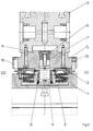
- Figures 1 and 2 show an embodiment of the present invention.
- a plate 1 with a or several quick release cylinders 2 with assigned Cover 3 provided.
- the lid 3 are each one Passed through nipple 4, which in turn in a Pallet 5 via a counter holder 6 and a threaded rod 7 is attached.
- the retractable nipple 4 is here with a Provided ring flange 8, which is in an associated Recess of the lid 3 creates and in this way Centering the retractable nipple and thus the associated one Pallet 5 ensures.
- the anti-rotation device between the pallet 5 and the Quick release cylinder 2 is shown in the Embodiment via a plurality of pins 10 which on the Pallet 5 are attached. These pens are made in high accuracy manufactured bores used and create assigned stop surfaces on the lid 3 of the Quick release cylinder. As already mentioned at the beginning, is the number of pins used 10 on the amount of Load dependent.
- the entire plate 1 can on a table 12 one Machine tool to be attached.
- the attachment can either, as shown, done via screws; but it can also be any other suitable mounting type can be used.
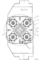
- Figures 3 and 4 show a special embodiment, in which the pins 19 of the on two of four sides Anti-rotation devices are designed eccentrically.
- the left pin 19 is shown so that the Eccentric is clearly recognizable.
- the right pin 10 is as ordinary round pen trained.
- To fix the Pallet 1 in this embodiment is sufficient if in a Rectangular, preferably viewed from the top view square arrangement, two not opposite each other arranged pins are eccentric.
- variable distance is important in this arrangement between the round pins 10 and the eccentric pins 19 which results from twisting the eccentric pins 19. This arrangement opens up the possibility of Anti-rotation device between pallet 1 and quick release cylinder 2 to adapt exactly to the dimensions of the components.
- FIGS. 5-9 A plate 1 is shown in FIGS. 5-9, which has five essentially identical quick release cylinders 2 is provided.
- the Plate 1 attached to the table 12 and in the direction of the arrow 13.14 rotatable.
- the blocking circle is in dashed lines indicated.
- the plate 1 can be fixed on the table 12 here either via dowel pins 15 with assigned screws respectively; but it is also possible to plate 1 again with one or more retractable nipples and this in assigned quick release cylinders of the table 12 record.
- the quick release cylinder 2 can be a schematically shown hydraulic connection with pressure oil be supplied to the retraction of the retractable nipple 4 cause.
- Figure 5 shows a view in which no pallets 5 are put on.
- the top two Quick release cylinder 2 each individually or with one shared pallet.
- the Diagonals are used; it is also possible to everyone Use quick release cylinder 2 individually.
- FIG. 6 shows an assembly of the Plate 1 with a total of four workpieces, the The middle place remains free. Each of these workpieces can thus on the three outer sides and on the top can be processed without having to reclamp. With it can also have a correspondingly small head also be possible to edit the inside.
- the plate 1 is e.g. in Direction of arrow 13 rotated by 90 °, whereupon the second workpiece is processed.
- the plate 1 can be turned by 180 ° by hand, too to edit the inside so far.
- different processing sequence can also be required be provided.
- Figure 7 shows workpieces in which such a rotation is not required.
- the difference compared to Figure 6 is that the inside is not processed like from the schematically illustrated holes according to FIG 6.7 results.
- FIGS. 6-8 enable significantly shorter transformation times. Especially in the Clamping according to Figures 7 and 8 can be done without any Span can be processed continuously. The changeover times of the The machine is reduced considerably.
- quick release cylinder 2 or the cover 3 By a suitable design of the quick release cylinder 2 or the cover 3 can thus be achieved that a single pallet with a single retractable nipple is held against rotation. At the same time, however, how So far, several quick release cylinders work together to create one single pallet to clamp.
Abstract
Description
Gegenstand der vorliegenden Erfindung ist eine Vorrichtung zum Spannen und lagerichtigen Positionieren von Paletten.The present invention relates to a device for clamping and correctly positioning pallets.
Mit einer auf denselben Anmelder zurückgehenden Veröffentlichung ist es bereits bekannt geworden, eine Palette über mehrere Einzugsnippel mit zugeordneten Schnellspannzylindern zu halten. Die Einzugsnippel werden hierbei in die Schnellspannzylinder eingeführt, in denen sie nach unten gezogen werden. Dieses Einziehen führt dazu, daß der Einzugsnippel bzw. ein zugeordnetes Bauteil, das an der Palette befestigt ist, gegenüber dem Schnellspannzylinder zentriert wird. Die Einzugskraft ist hierbei so hoch, daß die Palette völlig sicher und unverrückbar in einer lagerichtig genau bestimmten Stellung gegenüber dem Schnellspannzylinder gehalten wird.With one going back to the same applicant A publication has already become known Pallet over several retractable nipples with assigned Hold quick release cylinders. The retractable nipples are here inserted into the quick release cylinder in which they be pulled down. This feeding leads to the fact that the retractable nipple or an assigned component, which on the Pallet is attached to the quick release cylinder is centered. The pull-in force is so high that the Pallet completely safe and immovable in one correct position exactly defined position in relation to the quick release cylinder is held.
Es hat sich allerdings in der Praxis herausgestellt, daß es in einigen Fällen wünschenswert ist, relativ kleine Paletten zu verwenden. Diese Paletten müssen nicht mit mehreren Einzugsnippeln versehen werden, da bereits ein einziger Einzugsnippel für eine ausreichende Befestigung sorgt.In practice, however, it has been found that in some cases it is desirable to have relatively small pallets to use. These pallets do not have to have several Retractable nipples are provided, since there is already one Retractable nipple ensures adequate fastening.
Bei dem Verwenden nur eines einzigen Einzugsnippels besteht allerdings das Problem, daß die Palette zusammen mit dem Einzugsnippel gegenüber dem Schnellspannzylinder verdreht werden kann. Bei den bisher bekannten Paletten, die mit mehreren Einzugsnippeln arbeiten, bestand diese Gefahr nicht. Hier wird eine Verdrehsicherung durch das Anbringen mehrerer Einzugsnippel erreicht.When using only a single retractable nipple but the problem is that the pallet together with the Retractable nipple rotated in relation to the quick release cylinder can be. With the previously known pallets, which with work with several retractable nipples, there was no danger. Here is an anti-rotation device by attaching several Retractable nipple reached.
Aufgabe der vorliegenden Erfindung ist es daher, eine Vorrichtung der eingangs genannten Art dahingehend weiterzubilden, daß eine Palette mit nur einem einzigen Einzugsnippel in einer genau definierten Lage auf dem zugeordneten Schnellspannzylinder aufgesetzt und an diesem befestigt werden kann.The object of the present invention is therefore a Device of the type mentioned in this regard to train that a pallet with only one Retractable nipple in a precisely defined position on the assigned quick release cylinder placed on this can be attached.
Erfindungsgemäß wird diese Aufgabe durch die technische Lehre
des Anspruchs 1 gelöst.According to the invention, this task is achieved through technical teaching
of
Wesentlich hierbei ist, daß die Palette nur mit einem einzigen Einzugsnippel versehen ist, und gleichzeitig eine Verdrehsicherung zwischen der Palette und dem zugeordneten Schnellspannzylinder vorhanden ist. Diese Verdrehsicherung ist in der Form von Fixierstiften ausgebildet, die eine entsprechende mechanische Festigkeit aufweisen.It is essential that the pallet with only one single retractable nipple is provided, and at the same time one Protection against rotation between the pallet and the assigned one Quick release cylinder is available. This anti-rotation device is in the form of locating pins, the one have appropriate mechanical strength.
Hierdurch ergibt sich der wesentliche Vorteil, daß nunmehr relativ kleine Paletten nicht wie beim Stand der Technik mit mehreren Einzugsnippeln versehen werden müssen, sondern eine wesentliche Verringerung der Kosten und Vereinfachung der Konstruktion erreicht werden kann.This gives the main advantage that now relatively small pallets not like in the prior art several retractable nipples must be provided, but one significantly reduce costs and simplify Construction can be achieved.
Die Verdrehsicherung kann hierbei in mehreren Arten ausgebildet sein.The anti-rotation lock can be of several types be trained.
Eine erste Ausführungsform sieht vor, daß die Palette mit Stiften versehen ist, die sich an zugeordneten Anschlagflächen des Schnellspannzylinders anlegen. Selbstverständlich ist es ebenfalls möglich, diese Stifte an dem Schnellspannzylinder zu befestigen und die Anschlagflächen an der Palette vorzusehen.A first embodiment provides that the pallet with Pins are provided that are assigned to Place the stop surfaces of the quick release cylinder. Of course, it is also possible to attach these pens to attach the quick release cylinder and the Provide stop surfaces on the pallet.
Die Anzahl der Stifte richtet sich hierbei nach dem bei der Bearbeitung auftretenden Drehmoment. Je nach der Größe des Drehmoments können zwei, vier, sechs oder noch mehr dieser Stifte vorgesehen sein. The number of pens depends on the Machining occurring torque. Depending on the size of the Torques can be two, four, six or even more of these Pins may be provided.
In einer ersten Ausführungsform ist es vorgesehen, die Stifte für die Verdrehsicherung so anzuordnen, daß eine Schwenkmöglichkeit um 90°, also jeweils um einen rechten Winkel, erreicht wird. Dazu werden die Kontaktflächen des Schnellspannzuylinders entsprechend ausgebildet, so daß durch lösen der Verdrehsicherung die Palette entsprechend verdreht werden kann. Dadurch wird eine Bearbeitungsmöglichkeit der eingespannten Werkstücke in 90° Schritten erreicht.In a first embodiment, the pins are provided to arrange for the anti-rotation so that a Possibility to swivel by 90 °, i.e. by one on the right Angle. The contact surfaces of the Schnellspannzuylinders trained accordingly, so that by loosen the anti-rotation device the pallet is rotated accordingly can be. This makes it possible to edit the clamped workpieces reached in 90 ° steps.
Wie bereits erwähnt ist es auch möglich, diese Stifte an dem Schnellspannzylinder zu befestigen und die Anschlagflächen an der Palette vorzusehen.As already mentioned, it is also possible to attach these pins to the Fasten the quick release cylinder and the stop surfaces to provide the pallet.
Eine andere Ausführungsform sieht vor, daß die Anordnung der Stifte in 120° Winkeln erfolgt. Die zugeordneten Anschlagflächen des Schnellspannzylinders werden in diesem Fall sinnvollerweise ebenfalls in 120° Winkeln angeordnet. Somit kann das zu bearbeitende Werkstück bei Bedarf in dieser Winkelteilung verdreht werden.Another embodiment provides that the arrangement of the Pins are made at 120 ° angles. The assigned Stop surfaces of the quick release cylinder are in this Case also sensibly arranged at 120 ° angles. Thus, the workpiece to be machined can be in this if necessary Angle division can be rotated.
In einer vorteilhaften Weiterbildung der Erfindung ist
vorgesehen, die Verdrehsicherung derart auszubilden, daß die
Palette in mehreren Winkelstellungen auf dem
Schnellspannzylinder aufgesetzt und in diesen
Winkelstellungen zuverlässig gehalten werden kann.
Insbesondere bei manchen Bearbeitungsschritten kann es
erforderlich sein, die Palette zuerst in einer ersten
Stellung zu bearbeiten, anschließend um einen bestimmten
Winkel zu verdrehen, neu zu befestigen und dann wiederum zu
bearbeiten. Durch eine geeignete Wahl der Winkelschritte kann
die Verdrehsicherung entsprechend der Bearbeitungsvorgaben
extrem genau gegenüber dem Schnellspannzylinder gehalten
werden.
Es sind somit beliebige Winkelverstellungen möglich. In an advantageous development of the invention, it is provided that the anti-rotation device is designed in such a way that the pallet can be placed on the quick-release cylinder in several angular positions and can be held reliably in these angular positions. In some processing steps in particular, it may be necessary to first process the pallet in a first position, then to rotate it by a certain angle, to reattach it and then to process it again. By a suitable choice of the angular steps, the anti-rotation device can be held extremely precisely in relation to the quick-release cylinder according to the machining specifications.
Any angle adjustments are possible.
Ein wesentlicher Vorteil des Systems aus Einzugsnippel und Schnellspannzylinder besteht darin, daß die Palette selbst in genau definierter Stellung gegenüber der Werkzeugmaschine gehalten wird. Es wird bevorzugt, wenn die Palette selbst nun geeignete Anschlag- oder Anlageflächen für das oder die zu bearbeitenden Werkstücke aufweist, so daß diese ebenfalls, sobald die Palette festgespannt ist, in genau definierter Stellung vorliegen. Ein Nachrüsten bzw. Einstellen, um Montagetoleranzen auszugleichen, kann so vermieden werden.A major advantage of the system consisting of retractable nipple and Quick release cylinder is that the pallet itself in precisely defined position in relation to the machine tool is held. It is preferred if the pallet itself now suitable stop or contact surfaces for the or the has machining workpieces, so that they also, as soon as the pallet is clamped in precisely defined Position. A retrofit or adjustment to Compensating assembly tolerances can be avoided.
Der Erfindungsgegenstand der vorliegenden Erfindung ergibt sich nicht nur aus dem Gegenstand der einzelnen Patentansprüche, sondern auch aus der Kombination der einzelnen Patentansprüche untereinander.The subject matter of the present invention provides not just from the subject of each Claims, but also from the combination of individual claims among themselves.
Alle in den Unterlagen, einschließlich der Zusammenfassung, offenbarten Angaben und Merkmale, insbesondere die in den Zeichnungen dargestellte räumliche Ausbildung werden als erfindungswesentlich beansprucht, soweit sie einzeln oder in Kombination gegenüber dem Stand der Technik neu sind.All in the documentation, including the summary, Disclosed information and features, in particular those in the Drawings illustrated spatial training are considered essential to the invention, insofar as they are used individually or in Combination are new compared to the prior art.
Im folgenden wird die Erfindung anhand von lediglich einen Ausführungsweg darstellenden Zeichnungen näher erläutert. Hierbei gehen aus den Zeichnungen und ihrer Beschreibung weitere erfindungswesentliche Merkmale und Vorteile der Erfindung hervor.In the following the invention is based on only one Execution path illustrating drawings explained in more detail. Here go from the drawings and their description further features and advantages essential to the invention Invention.
Dabei zeigt:
- Figur 1:
- einen Schnitt durch eine erfindungsgemäße Vorrichtung;
- Figur 2:
- eine Draufsicht auf eine erfindungsgemäße Vorrichtung mit befestigter Palette;
- Figur 3:
- eine spezielle Ausführungsform der
Figur 1 mit exzentrisch ausgeführten Stiften; - Figur 4:
- eine Draufsicht auf eine erfindungsgemäße
Vorrichtung mit befestigter Palette nach
Figur 3; - Figur 5:
- eine Draufsicht auf eine vorteilhafte Weiterbildung in einer ersten Ausführung;
- Figur 6:
- eine Ansicht gemäß
Figur 5 in einer zweiten Ausführung; - Figur 7:
- eine Ansicht gemäß
Figur 5 in einer weiteren Ausführung; - Figur 8:
- eine Ansicht gemäß
Figur 5 in einer vierten Ausführung; - Figur 9:
- eine fünfte Ausführung in einer Ansicht gemäß
Figur 5.
- Figure 1:
- a section through a device according to the invention;
- Figure 2:
- a plan view of a device according to the invention with a fixed pallet;
- Figure 3:
- a special embodiment of Figure 1 with eccentrically designed pins;
- Figure 4:
- a plan view of a device according to the invention with a fixed pallet according to Figure 3;
- Figure 5:
- a plan view of an advantageous development in a first embodiment;
- Figure 6:
- a view of Figure 5 in a second embodiment;
- Figure 7:
- a view of Figure 5 in another embodiment;
- Figure 8:
- a view of Figure 5 in a fourth embodiment;
- Figure 9:
- a fifth embodiment in a view according to Figure 5.
Die Figuren 1 und 2 zeigen eine Ausführungsform der
vorliegenden Erfindung. Hierbei ist eine Platte 1 mit einem
oder mehreren Schnellspannzylindern 2 mit zugeordneten
Deckeln 3 versehen. Die Deckel 3 werden von jeweils einem
Einzugsnippel 4 durchgriffen, der seinerseits in einer
Palette 5 über einen Gegenhalter 6 und eine Gewindestange 7
befestigt ist. Der Einzugsnippel 4 ist hierbei mit einem
Ringflansch 8 versehen, der sich in einer zugeordneten
Ausnehmung des Deckels 3 anlegt und auf diese Weise eine
Zentrierung des Einzugsnippels und damit der zugeordneten
Palette 5 sicherstellt.Figures 1 and 2 show an embodiment of the
present invention. Here is a
An der Palette 5 in ein Werkstück 9 befestigt, das im
gezeigten Ausführungsbeispiel über einen Ansatz 11 der
Palette gegenüber dieser zentriert ist. Das Werkstück 9 liegt
somit in genau definierter Lage gegenüber der Platte 1 vor. Attached to the
Die Verdrehsicherung zwischen der Palette 5 und dem
Schnellspannzylinder 2 erfolgt im gezeigten
Ausführungsbeispiel über mehrere Stifte 10, die an der
Palette 5 befestigt sind. Diese Stifte werden in hochgenau
gefertigte Bohrungen eingesetzt und legen sich an
zugeordneten Anschlagflächen am Deckel 3 des
Schnellspannzylinders an. Wie bereits eingangs ausgeführt,
ist die Anzahl der verwendeten Stifte 10 von der Höhe der
Belastung abhängig.The anti-rotation device between the
Die gesamte Platte 1 kann auf einem Tisch 12 einer
Werkzeugmaschine befestigt werden.The
In der Draufsicht nach Figur 2 wird deutlich, daß die Stifte
10 an gegenüberliegenden Ecken des Deckels 3 vorgesehen sind.
Es ist auch deutlich der Ansatz 11 erkennbar, der im
gezeigten Ausführungsbeispiel kreisrund ausgeführt ist.In the plan view of Figure 2 it is clear that the
Es ist selbstverständlich ebenfalls möglich, nicht nur ein
einziges Werkstück 9 zu befestigen, sondern auch mehrere
Werkstücke. Die Befestigung kann entweder, wie dargestellt,
über Schrauben erfolgen; es kann aber auch jede andere
geeignete Befestigungsart verwendet werden.It is of course also possible, not just one
to fix
Die Figuren 3 und 4 zeigen eine spezielle Ausführungsform,
bei der an zwei von vier Seiten die Stifte 19 der
Verdrehsicherung exzentrisch ausgebildet sind.Figures 3 and 4 show a special embodiment,
in which the
In Figur 3 ist der linke Stift 19 so dargestellt, daß der
Exzenter deutlich erkennbar ist. Der rechte Stift 10 ist als
gewöhnlicher runder Stift ausgebildet. Zur Fixierung der
Palette 1 in dieser Ausführungsform genügt es, wenn in einer,
aus der Draufsicht betrachteten rechteckigen, vorzugsweise
quadratischen Anordnung, zwei sich nicht gegenüberliegend
angeordnete Stifte exzentrisch ausgebildet sind. In Figure 3, the
Das Prinzip dieser Fixierung ist aus der Anordnung in der
Draufsicht in Figur 4 erkennbar. Dabei wird eine im
wesentlichen quadratisch ausgeformte Palette 1 an ihren
jeweils gegenüberliegenden Seiten durch eine
Dreipunktfixierung festgehalten. Dabei erfolgt eine erste
Ausrichtung der Palette durch das übereinanderschieben von
Palette 1 und Schnellspannzylinder 3. Die Fixierung der
Palette 1 erfolgt über die Einstellung der exzentrisch
ausgeformten Stifte 19, so daß sich die Palette gegenüber dem
Schnellspannzylinder 2 in Richtung des Pfeiles 21 fixiert.
Dabei ist in dieser speziellen Ausführungsform eine Fixierung
durch 6 Stifte 10,19 vorgesehen. Diese Anordnung ist jedoch
nicht zwingend notwendig, und kann beliebig variiert oder
durch weitere Stifte in ihrer Haltekraft verstärkt werden. Es
ist also völlig freigestellt, in welcher Anordnung und Anzahl
die Verdrehsicherung der Palette ausgeführt wird.The principle of this fixation is from the arrangement in the
Top view recognizable in Figure 4. One is in
essentially square-shaped
Wichtig bei dieser Anordnung ist der variable Abstand
zwischen den runden Stiften 10 und den exzentrisch Stiften 19
der sich durch verdrehen der exzentrischen Stifte 19 ergibt.
Durch diese Anordnung eröffnet sich die Möglichkeit die
Verdrehsicherung zwischen Palette 1 und Schnellspannzylinder
2 exakt an die Abmessungen der Bauteile anzupassen.The variable distance is important in this arrangement
between the round pins 10 and the
In den Figuren 5 - 9 ist eine Platte 1 gezeigt, die mit fünf
im wesentlichen gleich ausgebildeten Schnellspannzylindern 2
versehen ist. In den gezeigten Ausführungsformen ist die
Platte 1 auf dem Tisch 12 befestigt und in Pfeilrichtung
13,14 verdrehbar. Der Sperrkreis ist hierbei in Strichlinien
angedeutet.A
Die Fixierung der Platte 1 auf dem Tisch 12 kann hierbei
entweder über Paßstifte 15 mit zugeordneten Schrauben
erfolgen; es ist aber ebenfalls möglich, die Platte 1
wiederum mit einem oder mehreren Einzugsnippeln zu versehen
und diese in zugeordneten Schnellspannzylindern des Tisches
12 aufzunehmen.The
Um die Einsatzmöglichkeiten zu erhöhen, kann neben der
Verdrehung in Pfeilrichtungen 13,14 zusätzlich ein
Verschwenken in Pfeilrichtung 16,17 vorgesehen sein.To increase the possible uses, in addition to the
Twist in the direction of
Die Schnellspannzylinder 2 können hierbei über einen
schematisch dargestellten Hydraulikanschluß mit Drucköl
versorgt werden, um das Einziehen der Einzugsnippel 4 zu
bewirken.The
Figur 5 zeigt eine Ansicht, bei der noch keine Paletten 5
aufgesetzt sind. Es ergeben sich vielfältige
Kombinationsmöglichkeiten. So können z.B. die oberen beiden
Schnellspannzylinder 2 jeder für sich einzeln oder mit einer
gemeinsamen Palette bestückt werden. Ebenso können die
Diagonalen verwendet werden; es ist auch möglich, jeden
Schnellspannzylinder 2 einzeln zu verwenden.Figure 5 shows a view in which no
Die Ausführungsform gemäß Figur 6 zeigt eine Bestückung der
Platte 1 mit insgesamt vier Werkstücken, wobei der
Mittelplatz frei bleibt. Jedes dieser Werkstücke kann somit
an den drei außen liegenden Seiten sowie an der Oberseite
bearbeitet werden, ohne daß ein Umspannen erfolgen muß. Mit
einem entsprechend kleinbauenden Kopf kann es darüber hinaus
ebenfalls möglich sein, auch die Innenseite zu bearbeiten.The embodiment according to FIG. 6 shows an assembly of the
Es wird hierbei zunächst jede Seite eines ersten Werkstücks
bearbeitet, anschließend wird die Platte 1 z.B. in
Pfeilrichtung 13 um 90° verdreht, worauf das zweite Werkstück
bearbeitet wird. Sobald alle Werkstücke 9 bearbeitet worden
sind, können sie von Hand um 180° verdreht werden, um auch
die bisher innen liegenden Seite zu bearbeiten. Je nach den
Anforderungen kann auch eine andere Bearbeitungsfolge
vorgesehen sein. First, each side of a first workpiece
processed, then the
Figur 7 zeigt Werkstücke, bei denen eine derartige Verdrehung nicht erforderlich ist. Der Unterschied gegenüber Figur 6 liegt darin, daß die Innenseite nicht bearbeitet wird, wie sich aus den schematisch dargestellten Bohrungen gemäß Figur 6,7 ergibt.Figure 7 shows workpieces in which such a rotation is not required. The difference compared to Figure 6 is that the inside is not processed like from the schematically illustrated holes according to FIG 6.7 results.
In der Ausführungsform gemäß Figur 8 ist lediglich ein
einziges Werkstück 9 zentrisch aufgespannt. Dieses Werkstück
kann ohne umspannenden Vorgang an fünf Seiten bearbeitet
werden.In the embodiment according to FIG. 8 there is only one
Die Ausführungsformen nach den Figuren 6 - 8 ermöglichen wesentlich geringere Umspannzeiten. Insbesondere in der Aufspannung nach den Figuren 7 und 8 kann ohne jegliches Umspannen durchgehend bearbeitet werden. Die Umrüstzeiten der Maschine reduzieren sich beträchtlich.The embodiments according to FIGS. 6-8 enable significantly shorter transformation times. Especially in the Clamping according to Figures 7 and 8 can be done without any Span can be processed continuously. The changeover times of the The machine is reduced considerably.
Figur 6 erfordert lediglich ein manuelles Umspannen, das ohne größeren Zeitaufwand vorgenommen werden kann.Figure 6 only requires manual reclamping without more time can be made.
In der Ausführungsform nach Figur 9 sind anstatt der Paletten
5 Backenfutter 18 vorgesehen. Diese Backenfutter 18 können
z.B. auf zugeordneten, etwas abgewandelten Paletten
entsprechend Figur 1 mit Schrauben oder auf andere Art und
Weise befestigt werden. Die Ausführungsform nach Figur 9
ermöglicht es, beispielsweise 5 Werkstücke gleichzeitig zu
bearbeiten, bei denen lediglich eine Bearbeitung von der
Oberseite her vorgesehen ist, wie z.B. das Einbringen von
Bohrungen in Wellen. Auch hier ist keinerlei Umspannen mehr
erforderlich.In the embodiment according to FIG. 9, instead of the
Durch eine geeignete Ausgestaltung der Schnellspannzylinder 2
bzw. deren Deckel 3 kann somit erreicht werden, daß eine
einzige Palette mit einem einzigen Einzugsnippel
verdrehsicher gehalten wird. Gleichzeitig können aber wie
bisher mehrere Schnellspannzylinder zusammenwirken, um eine
einzige Palette zu spannen.By a suitable design of the
Insgesamt ergibt sich die Möglichkeit, mit wesentlich kleineren Paletten bei geringerem Fertigungsaufwand zu arbeiten. Overall, the possibility arises with essential smaller pallets with less manufacturing effort work.
Claims (8)
Applications Claiming Priority (2)
| Application Number | Priority Date | Filing Date | Title |
|---|---|---|---|
| DE19716797A DE19716797A1 (en) | 1997-04-22 | 1997-04-22 | Correct one-nipple clamping |
| DE19716797 | 1997-04-22 |
Publications (3)
| Publication Number | Publication Date |
|---|---|
| EP0873818A2 true EP0873818A2 (en) | 1998-10-28 |
| EP0873818A3 EP0873818A3 (en) | 1999-04-07 |
| EP0873818B1 EP0873818B1 (en) | 2003-04-02 |
Family
ID=7827274
Family Applications (1)
| Application Number | Title | Priority Date | Filing Date |
|---|---|---|---|
| EP98107223A Expired - Lifetime EP0873818B1 (en) | 1997-04-22 | 1998-04-21 | Correct positioning with single nipple clamping |
Country Status (5)
| Country | Link |
|---|---|
| US (1) | US6139002A (en) |
| EP (1) | EP0873818B1 (en) |
| JP (1) | JPH1110468A (en) |
| AT (1) | ATE235990T1 (en) |
| DE (2) | DE19716797A1 (en) |
Cited By (3)
| Publication number | Priority date | Publication date | Assignee | Title |
|---|---|---|---|---|
| EP0936025A2 (en) * | 1998-02-10 | 1999-08-18 | Stark, Emil, jr. | Clamping system with clamping cylinder and clamping part |
| EP1048397A2 (en) * | 1999-04-17 | 2000-11-02 | Emil Stark | Fixation of a connecting pin to a workpiece or a pallet |
| DE10317349B4 (en) * | 2003-04-15 | 2018-01-25 | Andreas Maier Gmbh & Co. Kg | Combination of a quick-release cylinder and a correctly positioned workpiece pallet resting on the same |
Families Citing this family (16)
| Publication number | Priority date | Publication date | Assignee | Title |
|---|---|---|---|---|
| US6186711B1 (en) * | 1998-04-03 | 2001-02-13 | Axxess Technologies, Inc. | Engraving system |
| DE19829955A1 (en) * | 1998-07-04 | 2000-01-05 | System 3R International Ab Vae | Connector for use in a coupling device |
| JP3338669B2 (en) | 1999-08-03 | 2002-10-28 | 株式会社コスメック | Clamping device with datum function |
| JP2002361533A (en) | 2001-06-07 | 2002-12-18 | Kosmek Ltd | Clamp device with datum function |
| EP1302278A1 (en) | 2001-10-12 | 2003-04-16 | Kabushiki Kaisha Kosmek | Clamping apparatus |
| DK1344599T3 (en) * | 2002-03-11 | 2004-10-04 | Erowa Ag | Clamping device with a centering cartridge and a clamping pin which can be clamped therein |
| US20040018048A1 (en) * | 2002-07-26 | 2004-01-29 | Sausen Earl W. | Pneumatic docking system |
| WO2004060606A1 (en) * | 2002-12-27 | 2004-07-22 | Kosmek Ltd. | Positioning device |
| JP4336558B2 (en) * | 2003-10-07 | 2009-09-30 | ヤマザキマザック株式会社 | Jig plate |
| DE102004017911A1 (en) * | 2004-04-13 | 2005-11-03 | Bayerische Motoren Werke Ag | Clamping device for workpiece has quit-clamping cylinder in machine table or clamping plate, with clamping mandrel screwed into workpiece |
| EP1693147A1 (en) * | 2005-02-16 | 2006-08-23 | Cross Hüller GmbH | Twinspindle machine tool with two workholders, one of which is adjustable |
| ES2300903T3 (en) * | 2005-07-09 | 2008-06-16 | System 3R International Ab | TIGHTENING DEVICE FOR A TOOL OR A WORK PIECE. |
| TW200732083A (en) * | 2006-01-30 | 2007-09-01 | Tool Internat Ag F | Clamping apparatus |
| JP2008183651A (en) * | 2007-01-29 | 2008-08-14 | Toyota Motor Corp | Clamping device of stage change plate |
| CN105751144B (en) * | 2016-04-27 | 2017-10-31 | 中车青岛四方机车车辆股份有限公司 | The installation system of pallet and turntable |
| US11478901B2 (en) * | 2020-06-04 | 2022-10-25 | Rimeco Products, Inc. | Pneumatic fixture clamp |
Citations (5)
| Publication number | Priority date | Publication date | Assignee | Title |
|---|---|---|---|---|
| DE3228827A1 (en) * | 1981-08-04 | 1983-02-24 | AIOI Seiki K.K., Itami, Hyogo | DEVICE FOR POSITIONING AND TIGHTENING A CLAMPING RANGE FOR MACHINE TOOLS |
| JPS62255042A (en) * | 1986-04-30 | 1987-11-06 | Tsudakoma Ind Co Ltd | Clamping device |
| EP0450383A1 (en) * | 1990-04-03 | 1991-10-09 | Lebrecht, Horst, Dipl.-Ing (FH) | Fastening and centring device |
| DE4135418A1 (en) * | 1991-10-26 | 1993-05-27 | Emil Stark Gmbh | Clamping fixture for fixing plate on carrier plate of processing machine - has bolts to lock plates, springs to maintain connection, and hydraulic piston for release, balls in cage engage grooves in bolt and piston |
| JPH0811031A (en) * | 1994-06-29 | 1996-01-16 | Olympus Optical Co Ltd | Pallet and chucking device of pallet |
Family Cites Families (14)
| Publication number | Priority date | Publication date | Assignee | Title |
|---|---|---|---|---|
| US3986617A (en) * | 1975-07-14 | 1976-10-19 | Sundstrand Corporation | Indexing pallet carrier for machine tools |
| US4703916A (en) * | 1986-06-12 | 1987-11-03 | Shinn Fu Corporation | Hydraulic jack structural improvement in one-way hydraulic path in association with safety pressure relief network |
| DE3820870A1 (en) * | 1987-06-23 | 1989-05-24 | Forkardt Paul Gmbh | Device for centring an interchangeable pallet with regard to a clamping-fixture axis and positioning device intended for this |
| DE3824824A1 (en) * | 1988-07-21 | 1990-01-25 | Hauni Werke Koerber & Co Kg | Device for positioning workpieces |
| JP2906058B2 (en) * | 1988-08-23 | 1999-06-14 | 株式会社森精機製作所 | Machine tool table equipment |
| DE3902854A1 (en) * | 1989-02-01 | 1990-08-02 | Gedib Ingenieurbuero U Innovat | Production apparatus with change pallets |
| DE3919077C1 (en) * | 1989-06-10 | 1990-07-26 | Erowa Ag, Reinach, Ch | |
| IT1238059B (en) * | 1990-02-09 | 1993-06-26 | Salvagnini Transferica Spa Ora | ADJUSTABLE TYPE OF ANCHORING ELEMENTS COMPONENTS FOR PARTS LOCKING EQUIPMENT ON A SUPPORT PALLET |
| DE4116103A1 (en) * | 1991-05-17 | 1992-11-19 | Hirschmann Gmbh | Coupling for tool or part holding mechanisms - has square cross=section with cylindrical rollers positioned along diagonals to locate in slots in tool holder |
| DE9203992U1 (en) * | 1991-05-17 | 1992-05-21 | Hirschmann Gmbh, 7239 Fluorn-Winzeln, De | |
| DE4307342C2 (en) * | 1993-03-09 | 1994-12-08 | Erowa Ag | Device for the position-defined clamping of a workpiece at the workplace of a processing machine |
| DE9307196U1 (en) * | 1993-05-12 | 1994-08-04 | Spreitzer Johann | Device unit for multi-sided machining of workpieces |
| DE4341743C2 (en) * | 1993-12-08 | 1998-01-29 | Emil Stark | Clamping plate for a clamping device with retractable nipple and method for producing the clamping plate |
| EP0785049B1 (en) * | 1996-01-15 | 2004-11-03 | Cianci, Pasquale, Dipl.-Ing | Support table with clamping device |
-
1997
- 1997-04-22 DE DE19716797A patent/DE19716797A1/en not_active Withdrawn
-
1998
- 1998-04-20 US US09/063,158 patent/US6139002A/en not_active Expired - Fee Related
- 1998-04-21 DE DE59807690T patent/DE59807690D1/en not_active Expired - Fee Related
- 1998-04-21 AT AT98107223T patent/ATE235990T1/en not_active IP Right Cessation
- 1998-04-21 JP JP10110937A patent/JPH1110468A/en active Pending
- 1998-04-21 EP EP98107223A patent/EP0873818B1/en not_active Expired - Lifetime
Patent Citations (5)
| Publication number | Priority date | Publication date | Assignee | Title |
|---|---|---|---|---|
| DE3228827A1 (en) * | 1981-08-04 | 1983-02-24 | AIOI Seiki K.K., Itami, Hyogo | DEVICE FOR POSITIONING AND TIGHTENING A CLAMPING RANGE FOR MACHINE TOOLS |
| JPS62255042A (en) * | 1986-04-30 | 1987-11-06 | Tsudakoma Ind Co Ltd | Clamping device |
| EP0450383A1 (en) * | 1990-04-03 | 1991-10-09 | Lebrecht, Horst, Dipl.-Ing (FH) | Fastening and centring device |
| DE4135418A1 (en) * | 1991-10-26 | 1993-05-27 | Emil Stark Gmbh | Clamping fixture for fixing plate on carrier plate of processing machine - has bolts to lock plates, springs to maintain connection, and hydraulic piston for release, balls in cage engage grooves in bolt and piston |
| JPH0811031A (en) * | 1994-06-29 | 1996-01-16 | Olympus Optical Co Ltd | Pallet and chucking device of pallet |
Cited By (5)
| Publication number | Priority date | Publication date | Assignee | Title |
|---|---|---|---|---|
| EP0936025A2 (en) * | 1998-02-10 | 1999-08-18 | Stark, Emil, jr. | Clamping system with clamping cylinder and clamping part |
| EP0936025A3 (en) * | 1998-02-10 | 2002-04-17 | Stark Werkzeuggesellschaft mbH | Clamping system with clamping cylinder and clamping part |
| EP1048397A2 (en) * | 1999-04-17 | 2000-11-02 | Emil Stark | Fixation of a connecting pin to a workpiece or a pallet |
| EP1048397A3 (en) * | 1999-04-17 | 2002-06-12 | Stark Werkzeuggesellschaft mbH | Fixation of a connecting pin to a workpiece or a pallet |
| DE10317349B4 (en) * | 2003-04-15 | 2018-01-25 | Andreas Maier Gmbh & Co. Kg | Combination of a quick-release cylinder and a correctly positioned workpiece pallet resting on the same |
Also Published As
| Publication number | Publication date |
|---|---|
| EP0873818B1 (en) | 2003-04-02 |
| EP0873818A3 (en) | 1999-04-07 |
| DE19716797A1 (en) | 1998-11-05 |
| US6139002A (en) | 2000-10-31 |
| DE59807690D1 (en) | 2003-05-08 |
| JPH1110468A (en) | 1999-01-19 |
| ATE235990T1 (en) | 2003-04-15 |
Similar Documents
| Publication | Publication Date | Title |
|---|---|---|
| EP0873818B1 (en) | Correct positioning with single nipple clamping | |
| EP0985488B1 (en) | Clamping device for multiple workpieces | |
| DE3531160A1 (en) | TOOL CHANGER FOR A MACHINE TOOL | |
| EP0742081A2 (en) | Universal precision vice for a machine tool | |
| EP0198379A2 (en) | Gripper with an exchangeable gripper jaw | |
| DE202013101917U1 (en) | chuck | |
| EP0416610B1 (en) | Toolholder for a machine tool, especially for turning machines, with interchangeable tool holder | |
| WO1987004651A1 (en) | Device for retaining and handling a flat object | |
| EP0873816B1 (en) | Cylinder for positioning and quick-action clamping | |
| DE3617119A1 (en) | Adjustable indexable insert | |
| DE2840129C2 (en) | Device for clamping a workpiece on a machine tool table | |
| DE102005002093B3 (en) | Tool carrier system especially for turning machines or suchlike has unit for stabilizing of tool holders in respective housing with regard to tool carrier with individual support means extending between two spaced apart tool holders | |
| DE4118376A1 (en) | Workpiece clamp with internal cone face - incorporates face in bush turning in and clamped to body | |
| EP0275923A2 (en) | Clamping device for work pieces | |
| EP0761382B1 (en) | Device for positioning pieces in clamping devices | |
| DE19716800A1 (en) | Workpiece clamping via retractable nipple | |
| DE3441968A1 (en) | Article-fixer clamping device and machining process | |
| DE102018119980A1 (en) | Clamping or gripping device | |
| DE102017007905A1 (en) | Locking device for machine tools | |
| DE3708363A1 (en) | CHUCK FOR MACHINE TOOLS | |
| DE2943713C2 (en) | Bracket for mixing arms | |
| DE2839320A1 (en) | Three jaw chuck for square workpiece - has two clamping bars with end faces inclined to bar axes and third with Vee-notch | |
| EP1048397A2 (en) | Fixation of a connecting pin to a workpiece or a pallet | |
| DE4012468C2 (en) | ||
| DE202005018586U1 (en) | Work piece clamping device for use in machine, has clamping units including individual jaw, which is adjustable about defined range against force of spring arrangement or hydraulic or pneumatic piston while clamping work piece |
Legal Events
| Date | Code | Title | Description |
|---|---|---|---|
| PUAI | Public reference made under article 153(3) epc to a published international application that has entered the european phase |
Free format text: ORIGINAL CODE: 0009012 |
|
| AK | Designated contracting states |
Kind code of ref document: A2 Designated state(s): AT CH DE FR GB IT LI |
|
| AX | Request for extension of the european patent |
Free format text: AL;LT;LV;MK;RO;SI |
|
| PUAL | Search report despatched |
Free format text: ORIGINAL CODE: 0009013 |
|
| AK | Designated contracting states |
Kind code of ref document: A3 Designated state(s): AT BE CH CY DE DK ES FI FR GB GR IE IT LI LU MC NL PT SE |
|
| AX | Request for extension of the european patent |
Free format text: AL;LT;LV;MK;RO;SI |
|
| 17P | Request for examination filed |
Effective date: 19990930 |
|
| AKX | Designation fees paid |
Free format text: AT CH DE FR GB IT LI |
|
| RAP1 | Party data changed (applicant data changed or rights of an application transferred) |
Owner name: STARK WERKZEUGGESELLSCHAFT MBH |
|
| RIN1 | Information on inventor provided before grant (corrected) |
Inventor name: STARK WERKZEUGGESELLSCHAFT MBH |
|
| GRAG | Despatch of communication of intention to grant |
Free format text: ORIGINAL CODE: EPIDOS AGRA |
|
| RAP1 | Party data changed (applicant data changed or rights of an application transferred) |
Owner name: STARK SPANNSYSTEME GMBH |
|
| RIN1 | Information on inventor provided before grant (corrected) |
Inventor name: STARK SPANNSYSTEME GMBH |
|
| 17Q | First examination report despatched |
Effective date: 20020626 |
|
| GRAG | Despatch of communication of intention to grant |
Free format text: ORIGINAL CODE: EPIDOS AGRA |
|
| GRAG | Despatch of communication of intention to grant |
Free format text: ORIGINAL CODE: EPIDOS AGRA |
|
| GRAH | Despatch of communication of intention to grant a patent |
Free format text: ORIGINAL CODE: EPIDOS IGRA |
|
| GRAH | Despatch of communication of intention to grant a patent |
Free format text: ORIGINAL CODE: EPIDOS IGRA |
|
| GRAA | (expected) grant |
Free format text: ORIGINAL CODE: 0009210 |
|
| AK | Designated contracting states |
Designated state(s): AT CH DE FR GB IT LI |
|
| PG25 | Lapsed in a contracting state [announced via postgrant information from national office to epo] |
Ref country code: IT Free format text: LAPSE BECAUSE OF FAILURE TO SUBMIT A TRANSLATION OF THE DESCRIPTION OR TO PAY THE FEE WITHIN THE PRESCRIBED TIME-LIMIT;WARNING: LAPSES OF ITALIAN PATENTS WITH EFFECTIVE DATE BEFORE 2007 MAY HAVE OCCURRED AT ANY TIME BEFORE 2007. THE CORRECT EFFECTIVE DATE MAY BE DIFFERENT FROM THE ONE RECORDED. Effective date: 20030402 Ref country code: GB Free format text: LAPSE BECAUSE OF FAILURE TO SUBMIT A TRANSLATION OF THE DESCRIPTION OR TO PAY THE FEE WITHIN THE PRESCRIBED TIME-LIMIT Effective date: 20030402 Ref country code: FR Free format text: LAPSE BECAUSE OF FAILURE TO SUBMIT A TRANSLATION OF THE DESCRIPTION OR TO PAY THE FEE WITHIN THE PRESCRIBED TIME-LIMIT Effective date: 20030402 |
|
| REG | Reference to a national code |
Ref country code: GB Ref legal event code: FG4D Free format text: NOT ENGLISH |
|
| RIN1 | Information on inventor provided before grant (corrected) |
Inventor name: STARK, EMIL, JR |
|
| REG | Reference to a national code |
Ref country code: CH Ref legal event code: EP |
|
| REG | Reference to a national code |
Ref country code: CH Ref legal event code: NV Representative=s name: BOVARD AG PATENTANWAELTE |
|
| REF | Corresponds to: |
Ref document number: 59807690 Country of ref document: DE Date of ref document: 20030508 Kind code of ref document: P |
|
| GBV | Gb: ep patent (uk) treated as always having been void in accordance with gb section 77(7)/1977 [no translation filed] |
Effective date: 20030402 |
|
| PLBE | No opposition filed within time limit |
Free format text: ORIGINAL CODE: 0009261 |
|
| STAA | Information on the status of an ep patent application or granted ep patent |
Free format text: STATUS: NO OPPOSITION FILED WITHIN TIME LIMIT |
|
| EN | Fr: translation not filed | ||
| 26N | No opposition filed |
Effective date: 20040105 |
|
| PGFP | Annual fee paid to national office [announced via postgrant information from national office to epo] |
Ref country code: AT Payment date: 20050421 Year of fee payment: 8 |
|
| PGFP | Annual fee paid to national office [announced via postgrant information from national office to epo] |
Ref country code: CH Payment date: 20050422 Year of fee payment: 8 |
|
| PG25 | Lapsed in a contracting state [announced via postgrant information from national office to epo] |
Ref country code: AT Free format text: LAPSE BECAUSE OF NON-PAYMENT OF DUE FEES Effective date: 20060421 |
|
| PG25 | Lapsed in a contracting state [announced via postgrant information from national office to epo] |
Ref country code: LI Free format text: LAPSE BECAUSE OF NON-PAYMENT OF DUE FEES Effective date: 20060430 Ref country code: CH Free format text: LAPSE BECAUSE OF NON-PAYMENT OF DUE FEES Effective date: 20060430 |
|
| PGFP | Annual fee paid to national office [announced via postgrant information from national office to epo] |
Ref country code: DE Payment date: 20060430 Year of fee payment: 9 |
|
| REG | Reference to a national code |
Ref country code: CH Ref legal event code: PL |
|
| PG25 | Lapsed in a contracting state [announced via postgrant information from national office to epo] |
Ref country code: DE Free format text: LAPSE BECAUSE OF NON-PAYMENT OF DUE FEES Effective date: 20071101 |