EP0198379A2 - Gripper with an exchangeable gripper jaw - Google Patents
Gripper with an exchangeable gripper jaw Download PDFInfo
- Publication number
- EP0198379A2 EP0198379A2 EP86104705A EP86104705A EP0198379A2 EP 0198379 A2 EP0198379 A2 EP 0198379A2 EP 86104705 A EP86104705 A EP 86104705A EP 86104705 A EP86104705 A EP 86104705A EP 0198379 A2 EP0198379 A2 EP 0198379A2
- Authority
- EP
- European Patent Office
- Prior art keywords
- bolt
- coupling
- jaw
- gripping device
- gripper
- Prior art date
- Legal status (The legal status is an assumption and is not a legal conclusion. Google has not performed a legal analysis and makes no representation as to the accuracy of the status listed.)
- Granted
Links
Images

Classifications
-
- B—PERFORMING OPERATIONS; TRANSPORTING
- B25—HAND TOOLS; PORTABLE POWER-DRIVEN TOOLS; MANIPULATORS
- B25J—MANIPULATORS; CHAMBERS PROVIDED WITH MANIPULATION DEVICES
- B25J15/00—Gripping heads and other end effectors
- B25J15/04—Gripping heads and other end effectors with provision for the remote detachment or exchange of the head or parts thereof
- B25J15/0475—Exchangeable fingers
Definitions
- the spring arrangement is pretensioned in the longitudinal direction of the bolt opening, that is to say transversely to the coupling plug, and constantly strives to press the bolt into its locked position.
- the gripper jaw can only assume a precisely predetermined position with respect to the coupling plug if the bolt is guided without play in the bolt opening of the gripper jaw and in the lateral recess of the coupling plug, a condition that cannot be met in practice in the long run.
- the coupling plug has a shoulder-like approach on which the gripper jaw should rest; however, the spring arrangement can, if at all, exert only a small force on the gripper jaw in relation to its pretension in the direction of the attachment of the coupling plug.
- the bolt can be pressed into its release position with a rod-shaped tool against the resistance of the spring arrangement. If the coupling plug has been reinserted into the coupling opening for the re-use of the gripper jaw, it cannot be determined with the usual control of the gripping device whether the bolt has returned to its locked position or has jammed in its release position. There is therefore a risk that the gripper jaw is used without being securely locked to the coupling plug.
- the invention has for its object to develop a gripping device of the type described above such that its at least one interchangeable gripper jaw by means of a control, as is customary for such gripper devices, can be locked and detached from it reliably and in precise positional assignment to the coupling plug .
- the gripping device can be moved with drive means, which are assigned to it anyway in a known manner, in such a way that the second engagement surface of the bolt according to the invention abuts the jaw rest. While the bolt reaches its locking position in this way, a tension is created in the spring arrangement in the longitudinal direction of the coupling plug, which holds the gripper jaw in a position which is fixed, for example, by a stop surface on the supporting coupling part.
- the gripping device according to the invention is particularly suitable for handling machines (robots) and generally has two gripper jaws, each of which transports a workpiece from one processing station to the next.
- the gripping device according to the invention is also suitable Direction also for the transport of tools and for holding workpieces or tools during machining.
- the gripping device according to the invention can be configured similar to a three-jaw chuck with three gripper jaws for clamping a workpiece on an automatic lathe. In all these cases, it may be sufficient if one of two or more interacting gripper jaws can be exchanged in the manner according to the invention; in other cases, all gripper jaws of the gripping device can be exchanged.
- the spring arrangement is preferably arranged between the supporting coupling part, in which the coupling plug is guided in its longitudinal direction, and a head of the coupling plug.
- the coupling plug it is also possible for the coupling plug to be rigidly connected to the supporting coupling part and for the spring arrangement to be arranged between the interchangeable gripper jaw and the bolt.
- the coupling plug is attached to the interchangeable gripper jaw and the bolt is guided in the supporting coupling part.
- At least one taper pin is attached to the load-bearing coupling part or to the exchangeable gripper jaw parallel to the coupling plug, to which a complementary centering device on the gripper jaw or on the load-bearing coupling part is assigned.
- the coupling plug can engage in the coupling opening with considerable play, since it does not have to ensure the positioning of the interchangeable gripper jaw in relation to the supporting coupling part, but only has to transmit the force of the spring arrangement.
- Other known means, for example complementary ones can also be provided for the exact positioning of the gripper jaw in relation to the supporting coupling part Flat serrations, also known as Hirth tooth clutches.
- the latch has a depression in its wedge surface into which a foot of the coupling plug can be snapped. This results in a positive connection in the locking position of the bolt, which secures the bolt particularly reliably against unintentional displacement.
- the gripper jaw can contain at least one latching device, which strives to hold the bolt in its release position.
- the gripper jaw can contain at least one latching device which strives to hold the bolt in its locked position.
- the cheek rest expediently has a freely cantilevered holding plate above a storage surface, which fits into the bolt opening and with which the bolt can be moved into the release position.
- the two measures described above can be further developed jointly in that the holding plate has at least one recess into which the latching device assigned to the locking position of the bolt can be latched when the bolt is moved into the release position.
- the jaw rest can have a stop opposite the holding plate, against which the bolt with its second engagement surface can be pressed in order to be moved into the locked position.
- the jaw rest has a two-sided cantilevered holding plate and on both sides thereof a storage surface for a gripper jaw and a stop for the second engagement surface of the associated bolt.
- the gripping device shown has a only partially indicated gripper housing 10 with a pair of parallel guides 12, on which two base jaws 14 are slidably guided.
- the gripper housing 10 also contains a drive, not shown, of a known type, for example an electric servo motor, with which the base jaws can be moved in opposite directions via a known gear, also not shown.
- the gear unit can, for example, consist of a threaded spindle with two opposing threads and associated nuts, the threads having the same or different pitches, depending on whether the base jaws 14 are to be moved through the same or different paths.
- a supporting coupling part 18, which protrudes from the gripper housing 10 is fastened with screws 16, in the example shown downward. If here and below we speak from below and above, this refers to the representation in FIGS. 1, 3 and 4; in reality, the gripping device shown can take any position in space.
- An interchangeable gripper jaw 20 is coupled to each of the two supporting coupling parts 18 by means of a coupling, which is described in more detail below.
- Each of the two couplings includes a coupling opening 22 of circular cross section, as shown in FIGS. 1, 3 and 4, and a locking opening 24 of rectangular cross section arranged transversely thereto, both of which are formed in the relevant gripper jaw 20.
- a coupling plug 26 is slidably guided, which is designed as an essentially cylindrical bolt.
- the coupling plug 26 has a head 28 at its upper end and, in the vicinity of its lower end, a lateral recess 30 in the form of an annular groove with a conical boundary surface 32, to which a foot 34 connects.
- a flat, essentially rectangular bolt 36 is guided in the bolt opening 24, into which a slot 38 is made from one of its narrow sides.
- the slot 38 has a width in the region of its end that is only slightly larger than the diameter of the coupling plug 26 in the region of the recess 30; outwardly, the slot 38 widens to a width that is slightly larger than the diameter of the foot 34.
- a wedge surface 40 is formed on the underside of the latch 36 in such a way that the thickness of the latch decreases toward the narrow side from which the slot 38 originates.
- a substantially conical recess 42 is formed around the end of the slot 38 on the underside of the latch 36, into which the foot 34 can snap with its upper boundary surface 32.
- each. one of the two gripper jaws 20 arranged latch 36 are shown in Fig. 1 to 3 in a locked position in which they prevent the associated hitch tion plug 26 is pulled up out of the associated gripper jaw 20. In FIG. 4, however, each of the two latches 36 is shown in a release position in which the associated coupling plug 26 can be pulled out upwards by expanding the slot 38.
- each of the two gripper jaws 20 there is a resilient latching device 44 which snaps into a notch 46 of the associated latch 36 when the latch is in its release position. Furthermore, two latching devices 48 are arranged in each of the two gripper jaws 20, each of which latches into a notch 50 of the associated bolt 36 when the latter is in its locked position.
- Each of the two bolts 36 also has an engagement surface 52 facing the other bolt for forces in the direction of the release position and an engagement surface 54 facing away from the other bolt for forces in the direction of the blocking position; in the example shown, these attack surfaces are formed by the two end faces of the bolt.
- Each of the two load-bearing coupling parts 18 has a cylindrical cavity 56 machined from above, which is closed at the top by a screwed-on cover 58.
- the head 28 and the adjoining part of the associated coupling plug 26 and a spring arrangement 60 are accommodated in the cavity 56.
- the spring arrangement 60 is a plate spring assembly, which is arranged between the head 28 of the coupling plug 26 and a shoulder of the cavity 56.
- the coupling plug 26 is displaceable against the resistance of the spring arrangement 60 with respect to the load-bearing coupling part 18 and is held tensioned in the locked position of the associated bolt 36, as a result of which Gripper jaw 20 and coupling part 18 are clamped together.
- the coupling plug 26 has sufficient radial play with respect to the coupling part 18 and the gripper jaw 20 so that it cannot become jammed.
- the required exact positioning of each of the two interchangeable gripper jaws 20 in relation to the associated coupling part 18 is provided by a pair of tapered pins 62, which are each fastened in the associated coupling part 18 with a cylindrical pin 64 formed thereon, for example by pouring them out with synthetic resin.
- Each of the two taper pins 62 engages in a centering device 66, which is designed as an internally conical and externally cylindrical sleeve and is fastened in the associated gripper jaw 20, in the example shown also by pouring out with synthetic resin.
- At least one gripper finger 68 is attached to each of the two gripper jaws 20, which is adapted in the usual way to the shape of a workpiece or tool intended for handling and can be replaced together with the associated gripper jaw 20. If it is not necessary to arrange the gripper fingers 68 interchangeably, the supporting coupling parts 18 together with interchangeable gripper jaws 20 can be removed and the gripper fingers 68 can be fastened directly to the base jaws 14.
- a plurality of preferably jaw jaws 70 can be present, one of which is shown. It has two storage surfaces 72, each for a gripper jaw 20 and a base 74 arranged in between, on which a holding plate 76 is fastened in such a way that it projects above the base over each of the two storage surfaces.
- the holding plate 76 has cantilevered on each of its two Ends a pair of lateral recesses 78. Each of these two ends is at a distance which is greater than the length of each of the two bars 36, a stop 80 also belonging to the jaw rest 70 opposite.
- An attachment 82 is fastened in the center of the holding plate 76, from which two lateral pins 84 protrude in the same directions as the holding plate 76 and an upper pin 86 protrudes upwards in the middle.
- a centering plate 88 is assigned to the upper pin 86, which is recessed in the center and fastened to the underside of the gripper housing 10.
- the two gripper jaws 20 are placed on the two storage surfaces 72 according to FIGS. 1 to 3 and then moved towards one another by a closing movement of the gripping device until they abut one of the two lateral pins 84.
- the two ends of the holding plate 76 penetrate into one of the two bolt openings 24, abut against the engagement surface 52 of the associated bolt 36 and move it from the locked position according to FIGS. 1 to 3 into the release position according to FIG. 4.
- the two latching devices 48 each gripper jaw 20 snap into the two recesses 78 at the associated end of the holding plate 76, as a result of which the gripper jaws are held immovably on the jaw rest 70.
- the gripper housing 10 together with base jaws 14 is moved upward, so that the coupling plug 26 and taper pins 62 detach from the two gripper jaws 20.
- the gripper housing 10 is lowered over another jaw rest 70, which corresponds to the one shown, but carries gripper jaws 20 with different gripper fingers 68.
- the coupling plug 26 in the coupling openings 22 of these gripper jaws 20 have penetrated and at the same time the tapered pins 62 have penetrated into the centering devices 66, they are moved apart by an opening movement of the gripping device, whereby they are displaced on their storage surfaces 72 away from the holding plate 76 and each of the two bolts 36 with them its contact surface 54 abuts the associated stop 80.
- the latches 36 are shifted from their release position into their locking position, with their wedge surface 40 pulling down the foot 34 of the associated coupling plug 26 and thereby tensioning the associated spring arrangement 60.
- the gripper jaws 20 fastened in this way to the supporting coupling parts 18 are then moved away from the stops 80 by a slight closing movement of the gripping device, but without reaching the holding plate 76. From this position, which is shown in FIGS. 1 to 3, the gripping device can be moved upwards in order to work with the replaced gripper jaws 20.
Abstract
Description
Die Erfindung betrifft eine Greifvorrichtung, insbesondere für Handhabungsautomaten, bei der mindestens ein tragendes Kupplungsteil mit einer auswechselbaren Greiferbacke kuppelbar ist durch eine Kupplung mit
- - einer Kupplungsöffnung und einer quer dazu angeordneten Riegelöffnung im tragenden Kupplungsteil oder in der Greiferbacke,
- - einem Kupplungsstecker, der von der Greiferbacke oder vom tragenden Kupplungsteil wegragt, in die Kupplungsöffnung einsteckbar ist und eine seitliche Aussparung aufweist,
- - einem Riegel, der in einer Sperrstellung in die Riegelöffnung und die Aussparung zugleich eingreift und dadurch den Kupplungsstecker in der Kupplungsöffnung verriegelt,
- - wobei Greiferbacke, Kupplungsstecker und Riegel in der Sperrstellung durch eine Federanordnung miteinander verspannt sind,
- - und der Riegel eine Angriffsfläche für eine äußere Kraft aufweist, durch die er in eine Lösestellung bewegbar ist, in der sich der Kupplungsstecker aus der Kupplungsöffnung herausziehen läßt.
- a coupling opening and a transversely arranged bolt opening in the supporting coupling part or in the gripper jaw,
- a coupling plug which protrudes from the gripper jaw or from the supporting coupling part, can be inserted into the coupling opening and has a lateral recess,
- a bolt which, in a locked position, engages in the bolt opening and the recess at the same time and thereby locks the coupling plug in the coupling opening,
- - The gripper jaw, coupling plug and bolt are clamped together in the locked position by a spring arrangement,
- - And the bolt has a surface for an external force by which it can be moved into a release position in which the coupling plug can be pulled out of the coupling opening.
Bei einer bekannten Greifvorrichtung dieser Gattung (DE 33 06 510 A1) ist die Federanordnung in Längsrichtung der Riegelöffnung, also quer zum Kupplungsstecker, vorgespannt und ständig bestrebt, den Riegel in seine Sperrstellung zu drücken. Die Greiferbacke kann in Bezug auf den Kupplungsstecker nur dann eine genau vorbestimmte Lage einnehmen, wenn der Riegel in der Riegelöffnung der Greiferbacke und in der seitlichen Aussparung des Kupplungssteckers spielfrei geführt ist, eine Bedingung, die sich in der Praxis auf Dauer nicht einhalten läßt. Der Kupplungsstecker weist zwar einen schulterartigen Ansatz auf, an dem die Greiferbacke anliegen soll; die Federanordnung kann aber, wenn überhaupt, nur eine im Verhältnis zu ihrer Vorspannung geringe Kraft auf die Greiferbacke in Richtung zum Ansatz des Kupplungssteckers ausüben. Zum Herausziehen des Kupplungssteckers aus der Greiferbacke läßt sich der Riegel mit einem stangenförmigen Werkzeug gegen den Widerstand der Federanordnung in seine Lösestellung drücken. Wenn der Kupplungsstecker zur erneuten Benutzung der Greiferbacke wieder in deren Kupplungsöffnung eingesteckt worden ist, läßt sich mit der üblichen Steuerung der Greifvorrichtung nicht feststellen, ob der Riegel wieder in seine Sperrstellung gelangt ist oder sich etwa in seiner Lösestellung verklemmt hat. Es besteht deshalb die Gefahr, daß die Greiferbacke benutzt wird, ohne sicher mit dem Kupplungsstecker verriegelt zu sein.In a known gripping device of this type (DE 33 06 510 A1) the spring arrangement is pretensioned in the longitudinal direction of the bolt opening, that is to say transversely to the coupling plug, and constantly strives to press the bolt into its locked position. The gripper jaw can only assume a precisely predetermined position with respect to the coupling plug if the bolt is guided without play in the bolt opening of the gripper jaw and in the lateral recess of the coupling plug, a condition that cannot be met in practice in the long run. The coupling plug has a shoulder-like approach on which the gripper jaw should rest; however, the spring arrangement can, if at all, exert only a small force on the gripper jaw in relation to its pretension in the direction of the attachment of the coupling plug. To pull the coupling plug out of the gripper jaw, the bolt can be pressed into its release position with a rod-shaped tool against the resistance of the spring arrangement. If the coupling plug has been reinserted into the coupling opening for the re-use of the gripper jaw, it cannot be determined with the usual control of the gripping device whether the bolt has returned to its locked position or has jammed in its release position. There is therefore a risk that the gripper jaw is used without being securely locked to the coupling plug.
Der Erfindung liegt die Aufgabe zugrunde, eine Greifvorrichtung der eingangs beschriebenen Gattung derart weiterzubilden, daß ihre mindestens eine auswechselbare Greiferbacke mittels einer Steuerung, wie sie für solche Greifervorrichtungen üblich ist, zuverlässig und in genauer Lagezuordnung zum Kupplungsstecker mit diesem verriegelbar und wieder von ihm lösbar ist.The invention has for its object to develop a gripping device of the type described above such that its at least one interchangeable gripper jaw by means of a control, as is customary for such gripper devices, can be locked and detached from it reliably and in precise positional assignment to the coupling plug .
Die Aufgabe ist erfindungsgemäß dadurch gelöst, daß
- - die Federanordnung in Längsrichtung des Kupplungsstekkers spannbar ist,
- - der Riegel eine der genannten Angriffsfläche gegenüberliegende zweite Angriffsfläche für eine äußere Kraft aufweist, durch die er in die Sperrstellung bewegbar ist,
- - der Riegel ferner eine Keilfläche aufweist, die bei seiner Bewegung in die Sperrstellung mit einer am Kupplungsstecker ausgebildeten Begrenzungsfläche seiner Aussparung zusammenwirkt und die Federanordnung spannt, und
- - im Arbeitsbereich der Greiferbacke eine Backenablage angeordnet ist, gegen die der Riegel wahlweise mit seiner ersten oder zweiten Angriffsfläche drückbar ist.
- the spring arrangement can be tensioned in the longitudinal direction of the coupling plug,
- the bolt has a second engagement surface opposite the mentioned engagement surface for an external force, by means of which it can be moved into the locked position,
- - The bolt also has a wedge surface which, when it moves into the blocking position, interacts with a limiting surface of its recess formed on the coupling plug and tensions the spring arrangement, and
- - In the working area of the gripper jaw, a jaw rest is arranged, against which the bolt can be pressed with its first or second contact surface.
Damit wird erreicht, daß der Kupplungsstecker in die zugehörige Greiferbacke eingesteckt werden kann, ohne daß die Federanordnung Widerstand leistet. Erst wenn der Kupplungsstecker seine vorbestimmte Endstellung in Bezug auf die Greiferbacke erreicht hat, wird der Riegel aus der Lösestellung in die Sperrstellung verschoben. Zu diesem Zweck kann die Greifvorrichtung mit Antriebsmitteln, die ihr ohnehin in bekannter Weise zugeordnet sind, derart bewegt werden, daß die erfindungsgemäße zweite Angriffsfläche des Riegels gegen die Backenablage stößt. Während der Riegel auf diese Weise in seine Sperrstellung gelangt, entsteht in der Federanordnung eine in Längsrichtung des Kupplungssteckers wirksame Spannung, welche die Greiferbacke in einer Stellung hält, die beispielsweise durch eine Anschlagfläche am tragenden Kupplungsteil festgelegt ist.This ensures that the coupling plug can be inserted into the associated gripper jaw without the spring arrangement providing resistance. Only when the coupling plug has reached its predetermined end position in relation to the gripper jaw, is the bolt moved from the release position into the blocking position. For this purpose, the gripping device can be moved with drive means, which are assigned to it anyway in a known manner, in such a way that the second engagement surface of the bolt according to the invention abuts the jaw rest. While the bolt reaches its locking position in this way, a tension is created in the spring arrangement in the longitudinal direction of the coupling plug, which holds the gripper jaw in a position which is fixed, for example, by a stop surface on the supporting coupling part.
Die erfindungsgemäße Greifvorrichtung eignet sich besonders für Handhabungsautomaten (Roboter) und hat im allgemeinen zwei Greiferbacken, die jeweils ein Werkstück von einer Bearbeitungsstation zur nächsten transportieren. Darüber hinaus eignet sich die erfindungsgemäße Greifvorrichtung auch für den Transport von Werkzeugen sowie zum Festhalten von Werkstücken oder Werkzeugen während einer Bearbeitung. So kann die erfindungsgemäße Greifvorrichtung beispielsweise ähnlich einem Dreibackenfutter mit drei Greiferbacken zum Spannen eines Werkstücks an einem Drehautomaten ausgestaltet sein. In all diesen Fällen kann es genügen, wenn eine von zwei oder mehr zusammenwirkenden Greiferbacken in der erfindungsgemäßen Weise auswechselbar ist; in anderen Fällen sind sämtliche Greiferbacken der Greifvorrichtung auswechselbar.The gripping device according to the invention is particularly suitable for handling machines (robots) and generally has two gripper jaws, each of which transports a workpiece from one processing station to the next. The gripping device according to the invention is also suitable Direction also for the transport of tools and for holding workpieces or tools during machining. For example, the gripping device according to the invention can be configured similar to a three-jaw chuck with three gripper jaws for clamping a workpiece on an automatic lathe. In all these cases, it may be sufficient if one of two or more interacting gripper jaws can be exchanged in the manner according to the invention; in other cases, all gripper jaws of the gripping device can be exchanged.
Die Federanordnung ist vorzugsweise zwischen dem tragenden Kupplungsteil, in dem der Kupplungsstecker in seiner Längsrichtung verschiebbar geführt ist, und einem Kopf des Kupplungssteckers angeordnet. Es ist aber auch möglich, daß der Kupplungsstecker mit dem tragenden Kupplungsteil starr verbunden und die Federanordnung zwischen der auswechselbaren Greiferbacke und dem Riegel angeordnet ist. Eine weitere Alternative besteht darin, daß der Kupplungsstecker an der auswechselbaren Greiferbacke befestigt und der Riegel im tragenden Kupplungsteil geführt ist.The spring arrangement is preferably arranged between the supporting coupling part, in which the coupling plug is guided in its longitudinal direction, and a head of the coupling plug. However, it is also possible for the coupling plug to be rigidly connected to the supporting coupling part and for the spring arrangement to be arranged between the interchangeable gripper jaw and the bolt. Another alternative is that the coupling plug is attached to the interchangeable gripper jaw and the bolt is guided in the supporting coupling part.
Es ist ferner zweckmäßig, wenn am tragenden Kupplungsteil oder an der auswechselbaren Greiferbacke parallel zum Kupplungsstecker mindestens ein Kegelstift befestigt ist, dem eine komplementäre Zentriervorrichtung an der Greiferbacke bzw. am tragenden Kupplungsteil zugeordnet ist. In diesem Fall kann der Kupplungsstecker mit nennenswertem Spiel in die Kupplungsöffnung eingreifen, da er nicht für die Positionierung der auswechselbaren Greiferbacke in Bezug auf das tragende Kupplungsteil zu sorgen, sondern nur die Kraft der Federanordnung zu übertragen hat. Für die genaue Positionierung der Greiferbacke in bezug auf das tragende Kupplungsteil können auch andere bekannte Mittel vorgesehen sein, beispielsweise komplementäre Plan-Kerbverzahnungen, die auch als Hirth-Zahnkupplungen bekannt sind.It is also expedient if at least one taper pin is attached to the load-bearing coupling part or to the exchangeable gripper jaw parallel to the coupling plug, to which a complementary centering device on the gripper jaw or on the load-bearing coupling part is assigned. In this case, the coupling plug can engage in the coupling opening with considerable play, since it does not have to ensure the positioning of the interchangeable gripper jaw in relation to the supporting coupling part, but only has to transmit the force of the spring arrangement. Other known means, for example complementary ones, can also be provided for the exact positioning of the gripper jaw in relation to the supporting coupling part Flat serrations, also known as Hirth tooth clutches.
Es ist vorteilhaft, wenn der Riegel in seiner Keilfläche eine Vertiefung aufweist, in die ein Fuß des Kupplungssteckers einrastbar ist. Dadurch ergibt sich in der Sperrstellung des Riegels ein Formschluß, der den Riegel besonders zuverlässig gegen unbeabsichtigte Verschiebung sichert.It is advantageous if the latch has a depression in its wedge surface into which a foot of the coupling plug can be snapped. This results in a positive connection in the locking position of the bolt, which secures the bolt particularly reliably against unintentional displacement.
Die Greiferbacke kann mindestens eine Rastvorrichtung enthalten, die bestrebt ist, den Riegel in seiner Lösestellung festzuhalten.The gripper jaw can contain at least one latching device, which strives to hold the bolt in its release position.
Unabhängig davon kann die Greiferbacke mindestens eine Rastvorrichtung enthalten, die bestrebt ist, den Riegel in seiner Sperrstellung festzuhalten.Irrespective of this, the gripper jaw can contain at least one latching device which strives to hold the bolt in its locked position.
Die Backenablage weist zweckmäßigerweise oberhalb einer Ablagefläche eine frei auskragende, in die Riegelöffnung passende Halteplatte auf, mit der sich der Riegel in die Lösestellung verschieben läßt.The cheek rest expediently has a freely cantilevered holding plate above a storage surface, which fits into the bolt opening and with which the bolt can be moved into the release position.
Die beiden im vorstehenden beschriebenen Maßnahmen können gemeinsam dadurch weitergebildet sein, daß die Halteplatte mindestens eine Vertiefung aufweist, in welche die der Sperrstellung des Riegel zugeordnete Rastvorrichtung einrastbar ist, wenn der Riegel in die Lösestellung verschoben ist.The two measures described above can be further developed jointly in that the holding plate has at least one recess into which the latching device assigned to the locking position of the bolt can be latched when the bolt is moved into the release position.
Die Backenablage kann einen der Halteplatte gegenüberliegenden Anschlag aufweisen, gegen den der Riegel mit seiner zweiten Angriffsfläche drückbar ist, um in die Sperrstellung verschoben zu werden.The jaw rest can have a stop opposite the holding plate, against which the bolt with its second engagement surface can be pressed in order to be moved into the locked position.
Wenn die Greifvorrichtung zwei auswechselbare Greiferbakken aufweist, dann ist es zweckmäßig, daß die Backenablage eine zweiseitig frei auskragende Halteplatte und beiderseits davon je eine Ablagefläche für eine Greiferbacke und je einen Anschlag für die zweite Angriffsfläche des zugehörigen Riegels aufweist.If the gripper device two interchangeable gripper jaws ken, it is expedient that the jaw rest has a two-sided cantilevered holding plate and on both sides thereof a storage surface for a gripper jaw and a stop for the second engagement surface of the associated bolt.
Ein Ausführungsbeispiel der Erfindung wird im folgenden anhand schematischer Zeichnungen mit weiteren Einzelheiten beschrieben. Es zeigt:
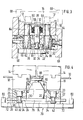
- Fig. 1 eine Greifvorrichtung in Seitenansicht und teilweise im Schnitt I-I in Fig. 2,
- Fig. 2 den Schnitt II-II in Fig. 1,
- Fig. 3 den Schnitt III-III in Fig. 1 und
- Fig. 4 eine der Fig. 1 ähnliche Seitenansicht der Greifvorrichtung in einer anderen Betriebsstellung.
- 1 is a gripping device in side view and partly in section II in Fig. 2,
- 2 shows the section II-II in Fig. 1,
- Fig. 3 shows the section III-III in Fig. 1 and
- Fig. 4 is a side view similar to Fig. 1 of the gripping device in another operating position.
Die dargestellte Greifvorrichtung hat ein nur teilweise angedeutetes Greifergehäuse 10 mit einem Paar paralleler Führungen 12, an denen zwei Grundbacken 14 verschiebbar geführt sind. Das Greifergehäuse 10 enthält ferner einen nicht dargestellten Antrieb bekannter Art, beispielsweise einen elektrischen Servomotor, mit dem die Grundbacken über ein ebenfalls nicht dargestelltes, bekanntes Getriebe gegenläufig bewegbar sind. Das Getriebe kann beispielsweise aus einer Gewindespindel mit zwei gegenläufigen Gewinden und zugehörigen Muttern bestehen, wobei die Gewinde gleiche oder ungleiche Steigungen aufweisen können, jenachdem ob die Grundbacken 14 um gleiche oder ungleiche Strecken bewegt werden sollen. An jeder der beiden Grundbacken 14 ist mit Schrauben 16 ein tragendes Kupplungsteil 18 befestigt, das aus dem Greifergehäuse 10 herausragt, im dargestellten Beispiel nach unten. Wenn hier und im folgenden von unten und oben die Rede ist, so bezieht sich dies auf die Darstellung in Fig. 1, 3 und 4; in Wirklichkeit kann die dargestellte Greifvorrichtung jede beliebige Lage im Raum einnehmen.The gripping device shown has a only partially indicated
Mit jedem der beiden tragenden Kupplungsteile 18 ist eine auswechselbare Greiferbacke 20 mittels einer Kupplung gekuppelt, die im folgenden näher beschrieben wird.An
Zu jeder der beiden Kupplungen gehören eine gemäß Fig. 1, 3 und 4 senkrechte Kupplungsöffnung 22 von kreisförmigem Querschnitt und eine quer dazu angeordnete Riegelöffnung 24 von rechteckigem Querschnitt, die beide in der betreffenden Greiferbacke 20 ausgebildet sind. In der Kupplungsöffnung 22 ist ein Kupplungsstecker 26 verschiebbar geführt, der als im wesentlichen zylindrischer Bolzen ausgebildet ist. Der Kupplungsstecker 26 hat an seinem oberen Ende einen Kopf 28 und in der Nähe seines unteren Endes eine seitliche Aussparung 30 in Gestalt einer Ringnut mit einer kegelförmigen Begrenzungsfläche 32, an die sich ein Fuß 34 anschließt.Each of the two couplings includes a
In der Riegelöffnung 24 ist ein flacher, im wesentlichen rechteckiger Riegel 36 geführt, in den von einer seiner Schmalseiten aus ein Schlitz 38 eingearbeitet ist. Der Schlitz 38 hat im Bereich seines Endes eine Breite, die nur wenig größer als der Durchmesser des Kupplungsteckers 26 im Bereich der Aussparung 30 ist; nach außen hin erweitert sich der Schlitz 38 auf eine Breite, die etwas größer als der Durchmesser des Fußes 34 ist. An der Unterseite des Riegels 36 ist eine Keilfläche 40 derart ausgebildet, daß die Dicke des Riegels sich zu derjenigen Schmalseite hin vermindert, von welcher der Schlitz 38 ausgeht. Rings um das Ende des Schlitzes 38 ist an der Unterseite des Riegels 36 eine im wesentlichen kegelförmige Vertiefung 42 ausgebildet, in die der Fuß 34 mit seiner oberen Begrenzungsfläche 32 einrasten kann.A flat, essentially
Die in je. einer der beiden Greiferbacken 20 angeordneten Riegel 36 sind in Fig. 1 bis 3 in einer Sperrstellung abgebildet, in der sie verhindern, daß der zugehörige Kupplungsstecker 26 nach oben aus der zugehörigen Greiferbacke 20 herausgezogen wird. In Fig. 4 ist jeder der beiden Riegel 36 hingegen in einer Lösestellung abgebildet, in welcher der zugehörige Kupplungsstecker 26 durch die Erweiterung des Schlitzes 38 nach oben herausgezogen werden kann.The in each. one of the two
In jeder der beiden Greiferbacken 20 ist eine federnde Rastvorrichtung 44 angeordnet, die in eine Kerbe 46 des zugehörigen Riegels 36 einrastet, wenn dieser seine Lösestellung einnimmt. Ferner sind in jeder der beiden Greiferbacken 20 zwei Rastvorrichtungen 48 angeordnet, die in je eine Kerbe 50 des zugehörigen Riegels 36 einrasten, wenn dieser seine Sperrstellung einnimmt.In each of the two
Jeder der beiden Riegel 36 hat ferner eine dem anderen Riegel zugewandte Angriffsfläche 52 für Kräfte in Richtung zur Lösestellung und eine vom anderen Riegel abgewandte Angriffsfläche 54 für Kräfte in Richtung zur Sperrstellung; diese Angriffsflächen sind im dargestellten Beispiel von den beiden Stirnseiten des Riegels gebildet.Each of the two
Jedes der beiden tragenden Kupplungsteile 18 hat einen von oben her eingearbeiteten zylindrischen Hohlraum 56, der nach oben hin durch einen aufgeschraubten Deckel 58 abgeschlossen ist. In dem Hohlraum 56 sind der Kopf 28 und der angegrenzende Teil des zugehörigen Kupplungssteckers 26 sowie eine Federanordnung 60 untergebracht. Die Federanordnung 60 ist im dargestellten Beispiel ein Tellerfederpaket, das zwischen dem Kopf 28 des Kupplungssteckers 26 und einem Absatz des Hohlraumes 56 angeordnet ist. Der Kupplungsstecker 26 ist gegen den Widerstand der Federanordnung 60 in Bezug auf das tragende Kupplungsteil 18 nach unten verschiebbar und ist in der Sperrstellung des zugehörigen Riegels 36 gespannt gehalten, wodurch Greiferbacke 20 und Kupplungsteil 18 zusammengespannt sind.Each of the two load-
Der Kupplungsstecker 26 hat in Bezug auf das Kupplungsteil 18 und die Greiferbacke 20 ausreichendes radiales Spiel, sodaß er sich nicht verklemmen kann. Für die erforderliche genaue Positionierung jeder der beiden auswechselbaren Greiferbacken 20 in Bezug auf das zugehörige Kupplungsteil 18 sorgt ein Paar Kegelstifte 62, die mit je einem an ihnen ausgebildeten zylindrischen Zapfen 64 im zugehörigen Kupplungsteil 18 befestigt sind, beispielsweise durch Ausgießen mit Kunstharz. Jeder der beiden Kegelstifte 62 greift in eine Zentriervorrichtung 66 ein, die als innen kegelförmige und außen zylindrische Büchse ausgebildet und in der zugehörigen Greiferbacke 20 befestigt ist, im dargestellten Beispiel ebenfalls durch Ausgießen mit Kunstharz.The
An jeder der beiden Greiferbacken 20 ist mindestens ein Greiferfinger 68 befestigt, der in üblicher Weise an die Form eines zur Handhabung vorgesehenen Werkstücks oder Werkzeugs angepaßt und zusammen mit der zugehörigen Greiferbacke 20 auswechselbar ist. Wenn es nicht erforderlich ist, die Greiferfinger 68 auswechselbar anzuordnen, so können die tragenden Kupplungsteile 18 samt auswechselbaren Greiferbacken 20 entfernt und die Greiferfinger 68 unmittelbar an den Grundbacken 14 befestigt werden.At least one
Zum Auswechseln und Aufbewahren der Greiferbacken 20 können mehrere vorzugsweise ortsfest angeordnete Backenablagen 70 vorhanden sein, von denen eine dargestellt ist. Sie hat zwei Ablageflächen 72 für je eine Greiferbacke 20 und einen dazwischen angeordneten Sockel 74, auf dem eine Halteplatte 76 derart befestigt ist, daß sie oberhalb jeder der beiden Ablageflächen über den Sockel auskragt. Die Halteplatte 76 hat an jedem ihrer beiden auskragenden Enden ein Paar seitliche Vertiefungen 78. Jedem dieser beiden Enden steht in einem Abstand, der größer ist als die Länge jedes der beiden Riegel 36, ein ebenfalls zur Backenablage 70 gehöriger Anschlag 80 gegenüber.To replace and store the
Auf der Halteplatte 76 ist mittig ein Aufsatz 82 befestigt, von dem zwei seitliche Zapfen 84 in den gleichen Richtungen wie die Halteplatte 76 wegragen und ein oberer Zapfen 86 mittig nach oben ragt. Dem oberen Zapfen 86 ist eine Zentrierplatte 88 zugeordnet, die mittig ausgespart und an der Unterseite des Greifergehäuses 10 befestigt ist.An
Wenn die beiden Greiferbacken 20 ausgewechselt werden sollen, werden sie gemäß Fig. 1 bis 3 auf den beiden Ablageflächen 72 abgesetzt und anschließend durch eine Schließbewegung der Greifvorrichtung soweit zueinander hin bewegt, bis sie gegen je einen der beiden seitlichen Zapfen 84 stoßen. Dabei dringen die beiden Enden der Halteplatte 76 in je eine der beiden Riegelöffnungen 24 ein, stoßen gegen die Angriffsfläche 52 des zugehörigen Riegels 36 und verschieben diesen aus der Sperrstellung gemäß Fig. 1 bis 3 in die Lösestellung gemäß Fig. 4. Die beiden Rastvorrichtungen 48 jeder Greiferbacke 20 rasten in die beiden Vertiefungen 78 am zugehörigen Ende der Halteplatte 76 ein, wodurch die Greiferbacken unverschiebbar auf der Backenablage 70 festgehalten werden. Anschließend wird das Greifergehäuse 10 samt Grundbacken 14 aufwärts bewegt, sodaß die Kupplungsstecker 26 und Kegelstifte 62 sich von den beiden Greiferbacken 20 lösen.If the two
Bei Bedarf wird das Greifergehäuse 10 über einer anderen Backenablage 70 abgesenkt, die mit der dargestellten übereinstimmt, jedoch Greiferbakken 20 mit anderen Greiferfingern 68 trägt. Sobald die Kupplungsstecker 26 in die Kupplungsöffnungen 22 dieser Greiferbacken 20 eingedrungen sind und zugleich die Kegelstifte 62 in die Zentriervorrichtungen 66 eingedrungen sind, werden sie durch eine öffnungsbewegung der Greifvorrichtung auseinander bewegt, wobei sie auf ihren Ablageflächen 72 von der Halteplatte 76 weg verschoben werden und jeder der beiden Riegel 36 mit seiner Angriffsfläche 54 gegen den zugehörigen Anschlag 80 stößt. Dadurch werden die Riegel 36 aus ihrer Lösestellung in ihre Sperrstellung verschoben, wobei sie mit ihrer Keilfläche 40 den Fuß 34 des zugehörigen Kupplungssteckers 26 nach unten ziehen und dadurch die zugehörige Federanordnung 60 spannen. Die auf diese Weise an den tragenden Kupplungsteilen 18 befestigten Greiferbacken 20 werden dann durch eine geringfügige Schließbewegung der Greifvorrichtung von den Anschlägen 80 wegbewegt, ohne jedoch die Halteplatte 76 zu erreichen. Aus dieser Stellung heraus, die in Fig. 1 bis 3 abgebildet ist, kann die Greifvorrichtung aufwärts bewegt werden, um mit den ausgewechselten Greiferbacken 20 zu arbeiten.If necessary, the
Claims (11)
dadurch gekennzeichnet, daß die Halteplatte (76) mindestens eine Vertiefung (78) aufweist, in welche die der Sperrstellung des Riegels (36) zugeordnete Rastvorrichtung (48) einrastbar ist, wenn der Riegel (36) in die Lösestellung verschoben ist.8. Gripping device according to claim 7 in connection with claim 6,
characterized in that the holding plate (76) has at least one recess (78) into which the latching device (48) associated with the locking position of the bolt (36) can be latched when the bolt (36) is displaced into the release position.
dadurch gekennzeichnet, daß die Backenablage (70) einen der Halteplatte (76) gegenüberliegenden Anschlag (80) aufweist, gegen den der Riegel (36) mit seiner zweiten Angriffsfläche (54) drückbar ist, um in die Sperrstellung verschoben zu werden.9. gripping device according to claim 7 or 8,
characterized in that the jaw rest (70) has a stop (80) opposite the holding plate (76), against which the bolt (36) with its second engagement surface (54) can be pressed in order to be moved into the locked position.
dadurch gekennzeichnet, daß die Backenablage (70) eine zweiseitig frei auskragende Halteplatte (76) und beiderseits davon je eine Ablagefläche (72) für eine Greiferbacke (20) und je einen Anschlag (80) für die zweite Angriffsfläche (54) des zugehörigen Riegels (36) aufweist.10. Gripping device according to claim 9, with two interchangeable gripper jaws (20),
characterized in that the jaw rest (70) has a holding plate (76) which projects freely on both sides and on both sides thereof a storage surface (72) for a gripper jaw (20) and a stop (80) for the second engagement surface (54) of the associated bolt ( 36).
Priority Applications (1)
| Application Number | Priority Date | Filing Date | Title |
|---|---|---|---|
| AT86104705T ATE35391T1 (en) | 1985-04-15 | 1986-04-07 | GRIPPER WITH INTERCHANGEABLE GRIPPER JAWS. |
Applications Claiming Priority (2)
| Application Number | Priority Date | Filing Date | Title |
|---|---|---|---|
| DE3513453 | 1985-04-15 | ||
| DE19853513453 DE3513453A1 (en) | 1985-04-15 | 1985-04-15 | GRIPPER WITH INTERCHANGEABLE GRIPPER JACK |
Publications (3)
| Publication Number | Publication Date |
|---|---|
| EP0198379A2 true EP0198379A2 (en) | 1986-10-22 |
| EP0198379A3 EP0198379A3 (en) | 1986-11-20 |
| EP0198379B1 EP0198379B1 (en) | 1988-06-29 |
Family
ID=6268057
Family Applications (1)
| Application Number | Title | Priority Date | Filing Date |
|---|---|---|---|
| EP86104705A Expired EP0198379B1 (en) | 1985-04-15 | 1986-04-07 | Gripper with an exchangeable gripper jaw |
Country Status (6)
| Country | Link |
|---|---|
| US (1) | US4715636A (en) |
| EP (1) | EP0198379B1 (en) |
| JP (1) | JPS61241087A (en) |
| AT (1) | ATE35391T1 (en) |
| BR (1) | BR8601670A (en) |
| DE (2) | DE3513453A1 (en) |
Cited By (6)
| Publication number | Priority date | Publication date | Assignee | Title |
|---|---|---|---|---|
| DE3727684A1 (en) * | 1987-08-19 | 1989-03-02 | Traub Ag | Arrangement for changing tools on a lathe |
| EP3305480A1 (en) * | 2016-10-10 | 2018-04-11 | Günther Zimmer | Quick tightening adapter with an interface for gripping elements |
| WO2018112388A1 (en) * | 2016-12-16 | 2018-06-21 | Soft Robotics, Inc. | Base systems for supporting soft robotic actuators |
| DE102020211768A1 (en) | 2020-09-21 | 2022-03-24 | Festo Se & Co. Kg | gripper device |
| WO2022078655A1 (en) * | 2020-10-14 | 2022-04-21 | Norgren Automation Solutions Llc | Fingers for workpiece holding devices |
| WO2023208549A3 (en) * | 2022-04-26 | 2023-12-21 | Khs Gmbh | Clamping-jaw-changeover system |
Families Citing this family (17)
| Publication number | Priority date | Publication date | Assignee | Title |
|---|---|---|---|---|
| DE3705884A1 (en) * | 1987-02-24 | 1988-09-01 | Fraunhofer Ges Forschung | Gripper system, in particular for industrial robots |
| DE3710297A1 (en) * | 1987-03-28 | 1988-10-13 | Fraunhofer Ges Forschung | Changing device for gripper jaws of an industrial robot |
| IT1211602B (en) * | 1987-12-15 | 1989-11-03 | Prima Ind Spa | ROBOTIC MANIPULATOR DEVICE PARTICULARLY FOR SHEETS WITH AUTOMATIC MECHANISM FOR GETTING INTERCHANGEABLE |
| US5256128A (en) * | 1990-01-17 | 1993-10-26 | Hewlett-Packard Company | Gripper exchange mechanism for small robots |
| DE19734832C1 (en) * | 1997-08-12 | 1998-10-22 | Festo Ag & Co | Coupling device for coupling gripping wedge to wedge support |
| US6569070B1 (en) * | 2002-01-09 | 2003-05-27 | Dallas Design And Technology, Inc. | System for changing the tooling carried by a robot |
| DE102004029051C5 (en) * | 2004-06-11 | 2011-09-15 | Schunk Gmbh & Co. Kg Spann- Und Greiftechnik | Fastening device for attaching a top jaw to a movably mounted base jaw of a linear or centric gripper and linear or centric gripper |
| US7967354B2 (en) * | 2008-05-06 | 2011-06-28 | Fanuc Robotics America, Inc. | Mixed size product handling end of arm tool |
| US8226141B2 (en) | 2010-03-30 | 2012-07-24 | Delaware Capital Formation, Inc. | Device for locking jaws of a gripper |
| CN102275167B (en) * | 2010-06-11 | 2013-11-20 | 鸿富锦精密工业(深圳)有限公司 | Clamping device |
| BR112015008363A2 (en) * | 2012-10-16 | 2017-07-04 | Beckman Coulter Inc | drain rail arrangement with remover feature |
| WO2016084122A1 (en) * | 2014-11-25 | 2016-06-02 | 富士機械製造株式会社 | Sales order processing device, identification information plate, and sales order processing method |
| US11565403B2 (en) * | 2018-10-09 | 2023-01-31 | Canon Kabushiki Kaisha | Attaching mechanism, robot apparatus, and attaching method |
| CN110371697B (en) * | 2019-08-09 | 2024-03-15 | 河南宾康智能装备有限公司 | Positioning type quick-replaceable clamping head for brick stacking machine |
| DE102020113413A1 (en) | 2020-05-18 | 2021-11-18 | Schunk Gmbh & Co. Kg Spann- Und Greiftechnik | Gripping device and a system comprising a gripping device and a magazine |
| CN113172799B (en) * | 2021-05-06 | 2022-10-04 | 上海和科设备制造有限公司 | Collecting pipe die carrying device |
| DE102021113553A1 (en) * | 2021-05-26 | 2022-12-01 | Syntegon Technology Gmbh | Gripping device and system comprising a gripping device |
Citations (4)
| Publication number | Priority date | Publication date | Assignee | Title |
|---|---|---|---|---|
| GB2130550A (en) * | 1982-11-27 | 1984-06-06 | Cleveland Guest | Robot hand |
| EP0120275A1 (en) * | 1983-03-11 | 1984-10-03 | Syspro | Tool carrier for an industrial robot |
| DE3426892A1 (en) * | 1983-07-25 | 1985-02-14 | Cincinnati Milacron Industries, Inc., Cincinnati, Ohio | TOOL CHANGE DEVICE FOR ROBOTS |
| EP0162187A1 (en) * | 1984-02-14 | 1985-11-27 | Carl Kurt Walther GmbH & Co. KG | Quick-coupling device for a tool holder at a robot hand |
Family Cites Families (5)
| Publication number | Priority date | Publication date | Assignee | Title |
|---|---|---|---|---|
| US3412459A (en) * | 1964-01-10 | 1968-11-26 | Giddings & Lewis | Automatic tool changing system |
| US4204303A (en) * | 1977-12-05 | 1980-05-27 | Eidam Lane L P | Locking mechanism for machine tool holder/adapter |
| DE3306510A1 (en) * | 1983-02-24 | 1984-08-30 | Rudi 4018 Langenfeld Kirst | Gripping device with a gripper jaw |
| US4601637A (en) * | 1984-03-16 | 1986-07-22 | International Business Machines Corporation | Manipulator gripper tool changing apparatus |
| US4613277A (en) * | 1984-04-16 | 1986-09-23 | Guay Roger G | Robotic head with interchangeable fingertips |
-
1985
- 1985-04-15 DE DE19853513453 patent/DE3513453A1/en not_active Withdrawn
-
1986
- 1986-03-14 US US06/839,683 patent/US4715636A/en not_active Expired - Fee Related
- 1986-04-07 AT AT86104705T patent/ATE35391T1/en not_active IP Right Cessation
- 1986-04-07 DE DE8686104705T patent/DE3660345D1/en not_active Expired
- 1986-04-07 EP EP86104705A patent/EP0198379B1/en not_active Expired
- 1986-04-11 JP JP61082408A patent/JPS61241087A/en active Pending
- 1986-04-14 BR BR8601670A patent/BR8601670A/en not_active IP Right Cessation
Patent Citations (4)
| Publication number | Priority date | Publication date | Assignee | Title |
|---|---|---|---|---|
| GB2130550A (en) * | 1982-11-27 | 1984-06-06 | Cleveland Guest | Robot hand |
| EP0120275A1 (en) * | 1983-03-11 | 1984-10-03 | Syspro | Tool carrier for an industrial robot |
| DE3426892A1 (en) * | 1983-07-25 | 1985-02-14 | Cincinnati Milacron Industries, Inc., Cincinnati, Ohio | TOOL CHANGE DEVICE FOR ROBOTS |
| EP0162187A1 (en) * | 1984-02-14 | 1985-11-27 | Carl Kurt Walther GmbH & Co. KG | Quick-coupling device for a tool holder at a robot hand |
Cited By (7)
| Publication number | Priority date | Publication date | Assignee | Title |
|---|---|---|---|---|
| DE3727684A1 (en) * | 1987-08-19 | 1989-03-02 | Traub Ag | Arrangement for changing tools on a lathe |
| EP3305480A1 (en) * | 2016-10-10 | 2018-04-11 | Günther Zimmer | Quick tightening adapter with an interface for gripping elements |
| WO2018112388A1 (en) * | 2016-12-16 | 2018-06-21 | Soft Robotics, Inc. | Base systems for supporting soft robotic actuators |
| US10369704B2 (en) | 2016-12-16 | 2019-08-06 | Soft Robotics, Inc. | Base systems for supporting soft robotic actuators |
| DE102020211768A1 (en) | 2020-09-21 | 2022-03-24 | Festo Se & Co. Kg | gripper device |
| WO2022078655A1 (en) * | 2020-10-14 | 2022-04-21 | Norgren Automation Solutions Llc | Fingers for workpiece holding devices |
| WO2023208549A3 (en) * | 2022-04-26 | 2023-12-21 | Khs Gmbh | Clamping-jaw-changeover system |
Also Published As
| Publication number | Publication date |
|---|---|
| US4715636A (en) | 1987-12-29 |
| DE3660345D1 (en) | 1988-08-04 |
| EP0198379A3 (en) | 1986-11-20 |
| ATE35391T1 (en) | 1988-07-15 |
| EP0198379B1 (en) | 1988-06-29 |
| DE3513453A1 (en) | 1986-10-16 |
| BR8601670A (en) | 1986-12-16 |
| JPS61241087A (en) | 1986-10-27 |
Similar Documents
| Publication | Publication Date | Title |
|---|---|---|
| EP0198379B1 (en) | Gripper with an exchangeable gripper jaw | |
| DE3426892C2 (en) | ||
| EP0101917B1 (en) | Cutting tool | |
| DE2746921C3 (en) | Device and method for making connections in and for testing pneumatic and hydraulic systems | |
| EP0742081B1 (en) | Universal precision vice for a machine tool | |
| DE102005031142A1 (en) | Clamping device, base jaws and top jaws for this | |
| DE102019100089B3 (en) | Clamping or gripping device | |
| EP0339321A1 (en) | Clamping device for the axial clamping of two machine parts seperable from each other | |
| DE102019116262B4 (en) | Clamping device and workpiece holding device with one clamping device | |
| DE3814550C1 (en) | Clamping device for clamping two machine parts releasable from one another | |
| DE3712820A1 (en) | MACHINE TOOL WITH TOOL CHANGE | |
| EP0428058A2 (en) | Chuck | |
| DE102020101064B3 (en) | Workpiece clamping device | |
| DE102020101059B4 (en) | Jig | |
| DE19636701A1 (en) | Device for clamping objects for the spindle of a machine tool | |
| DE3519754C2 (en) | ||
| EP0287777B1 (en) | Clamping device for tools or work pieces having a cylindrical shaft | |
| DE3420857A1 (en) | Gripping apparatus with gripper jaw | |
| EP0195184B1 (en) | Jaw-changing device | |
| EP2998068B1 (en) | Center tensioner with fast change jaws | |
| DE102019104836A1 (en) | Clamping device for a machine tool, in particular a machining center | |
| DE102019112952B4 (en) | Chucks for machine tools | |
| DE102020211768A1 (en) | gripper device | |
| DE1465310B2 (en) | CLAMPING PLIERS | |
| EP3616831A1 (en) | Clamping device |
Legal Events
| Date | Code | Title | Description |
|---|---|---|---|
| PUAI | Public reference made under article 153(3) epc to a published international application that has entered the european phase |
Free format text: ORIGINAL CODE: 0009012 |
|
| PUAL | Search report despatched |
Free format text: ORIGINAL CODE: 0009013 |
|
| AK | Designated contracting states |
Kind code of ref document: A2 Designated state(s): AT BE CH DE FR GB IT LI NL SE |
|
| AK | Designated contracting states |
Kind code of ref document: A3 Designated state(s): AT BE CH DE FR GB IT LI NL SE |
|
| RHK1 | Main classification (correction) |
Ipc: B25J 15/04 |
|
| 17P | Request for examination filed |
Effective date: 19861031 |
|
| 17Q | First examination report despatched |
Effective date: 19871104 |
|
| ITF | It: translation for a ep patent filed |
Owner name: BARZANO' E ZANARDO MILANO S.P.A. |
|
| GRAA | (expected) grant |
Free format text: ORIGINAL CODE: 0009210 |
|
| AK | Designated contracting states |
Kind code of ref document: B1 Designated state(s): AT BE CH DE FR GB IT LI NL SE |
|
| REF | Corresponds to: |
Ref document number: 35391 Country of ref document: AT Date of ref document: 19880715 Kind code of ref document: T |
|
| GBT | Gb: translation of ep patent filed (gb section 77(6)(a)/1977) | ||
| REF | Corresponds to: |
Ref document number: 3660345 Country of ref document: DE Date of ref document: 19880804 |
|
| ET | Fr: translation filed | ||
| PGFP | Annual fee paid to national office [announced via postgrant information from national office to epo] |
Ref country code: CH Payment date: 19890314 Year of fee payment: 4 Ref country code: AT Payment date: 19890314 Year of fee payment: 4 |
|
| PG25 | Lapsed in a contracting state [announced via postgrant information from national office to epo] |
Ref country code: SE Effective date: 19890408 |
|
| PLBE | No opposition filed within time limit |
Free format text: ORIGINAL CODE: 0009261 |
|
| STAA | Information on the status of an ep patent application or granted ep patent |
Free format text: STATUS: NO OPPOSITION FILED WITHIN TIME LIMIT |
|
| PGFP | Annual fee paid to national office [announced via postgrant information from national office to epo] |
Ref country code: DE Payment date: 19890428 Year of fee payment: 4 |
|
| PG25 | Lapsed in a contracting state [announced via postgrant information from national office to epo] |
Ref country code: BE Effective date: 19890430 |
|
| 26N | No opposition filed | ||
| BERE | Be: lapsed |
Owner name: TRAUB A.G. Effective date: 19890430 |
|
| PG25 | Lapsed in a contracting state [announced via postgrant information from national office to epo] |
Ref country code: NL Effective date: 19891101 |
|
| NLV4 | Nl: lapsed or anulled due to non-payment of the annual fee | ||
| PG25 | Lapsed in a contracting state [announced via postgrant information from national office to epo] |
Ref country code: FR Free format text: LAPSE BECAUSE OF NON-PAYMENT OF DUE FEES Effective date: 19891228 |
|
| REG | Reference to a national code |
Ref country code: FR Ref legal event code: ST |
|
| PG25 | Lapsed in a contracting state [announced via postgrant information from national office to epo] |
Ref country code: GB Effective date: 19900407 Ref country code: AT Effective date: 19900407 |
|
| ITTA | It: last paid annual fee | ||
| PG25 | Lapsed in a contracting state [announced via postgrant information from national office to epo] |
Ref country code: LI Effective date: 19900430 Ref country code: CH Effective date: 19900430 |
|
| GBPC | Gb: european patent ceased through non-payment of renewal fee | ||
| REG | Reference to a national code |
Ref country code: CH Ref legal event code: PL |
|
| PG25 | Lapsed in a contracting state [announced via postgrant information from national office to epo] |
Ref country code: DE Effective date: 19910101 |
|
| EUG | Se: european patent has lapsed |
Ref document number: 86104705.8 Effective date: 19900412 |
|
| PG25 | Lapsed in a contracting state [announced via postgrant information from national office to epo] |
Ref country code: IT Free format text: LAPSE BECAUSE OF NON-PAYMENT OF DUE FEES;WARNING: LAPSES OF ITALIAN PATENTS WITH EFFECTIVE DATE BEFORE 2007 MAY HAVE OCCURRED AT ANY TIME BEFORE 2007. THE CORRECT EFFECTIVE DATE MAY BE DIFFERENT FROM THE ONE RECORDED. Effective date: 20050407 |