EP0873668B1 - Implantierbares hörhilfegerät - Google Patents
Implantierbares hörhilfegerät Download PDFInfo
- Publication number
- EP0873668B1 EP0873668B1 EP96935881A EP96935881A EP0873668B1 EP 0873668 B1 EP0873668 B1 EP 0873668B1 EP 96935881 A EP96935881 A EP 96935881A EP 96935881 A EP96935881 A EP 96935881A EP 0873668 B1 EP0873668 B1 EP 0873668B1
- Authority
- EP
- European Patent Office
- Prior art keywords
- microactuator
- transducer
- hearing aid
- microphone
- subject
- Prior art date
- Legal status (The legal status is an assumption and is not a legal conclusion. Google has not performed a legal analysis and makes no representation as to the accuracy of the status listed.)
- Expired - Lifetime
Links
- 238000012545 processing Methods 0.000 claims abstract description 41
- 239000012530 fluid Substances 0.000 claims abstract description 40
- 210000003027 ear inner Anatomy 0.000 claims abstract description 37
- 229910052751 metal Inorganic materials 0.000 claims abstract description 31
- 239000002184 metal Substances 0.000 claims abstract description 31
- 239000002033 PVDF binder Substances 0.000 claims abstract description 29
- 229920002981 polyvinylidene fluoride Polymers 0.000 claims abstract description 29
- 239000000463 material Substances 0.000 claims abstract description 28
- 238000002513 implantation Methods 0.000 claims abstract description 21
- 239000011195 cermet Substances 0.000 claims description 29
- 210000001050 stape Anatomy 0.000 claims description 23
- 210000000959 ear middle Anatomy 0.000 claims description 22
- 230000004044 response Effects 0.000 claims description 12
- 230000008878 coupling Effects 0.000 claims description 8
- 238000010168 coupling process Methods 0.000 claims description 8
- 238000005859 coupling reaction Methods 0.000 claims description 8
- 239000002775 capsule Substances 0.000 claims description 7
- 241000878128 Malleus Species 0.000 claims description 6
- 210000001785 incus Anatomy 0.000 claims description 6
- 210000002331 malleus Anatomy 0.000 claims description 6
- 210000000860 cochlear nerve Anatomy 0.000 claims description 5
- 239000000835 fiber Substances 0.000 claims description 5
- 239000000919 ceramic Substances 0.000 claims description 3
- 230000000638 stimulation Effects 0.000 claims description 3
- 239000004020 conductor Substances 0.000 claims description 2
- 238000007920 subcutaneous administration Methods 0.000 claims description 2
- 239000000203 mixture Substances 0.000 claims 1
- 210000004049 perilymph Anatomy 0.000 abstract description 39
- 238000006073 displacement reaction Methods 0.000 abstract description 22
- 230000003321 amplification Effects 0.000 abstract description 5
- 238000003199 nucleic acid amplification method Methods 0.000 abstract description 5
- 241000208967 Polygala cruciata Species 0.000 abstract description 2
- 210000000883 ear external Anatomy 0.000 description 16
- 210000003454 tympanic membrane Anatomy 0.000 description 14
- 210000000613 ear canal Anatomy 0.000 description 13
- 210000000988 bone and bone Anatomy 0.000 description 12
- 210000001519 tissue Anatomy 0.000 description 12
- 210000003477 cochlea Anatomy 0.000 description 10
- 238000000034 method Methods 0.000 description 10
- PXHVJJICTQNCMI-UHFFFAOYSA-N Nickel Chemical compound [Ni] PXHVJJICTQNCMI-UHFFFAOYSA-N 0.000 description 8
- 238000005259 measurement Methods 0.000 description 7
- 210000003370 receptor cell Anatomy 0.000 description 7
- 210000001605 scala vestibuli Anatomy 0.000 description 7
- RTAQQCXQSZGOHL-UHFFFAOYSA-N Titanium Chemical compound [Ti] RTAQQCXQSZGOHL-UHFFFAOYSA-N 0.000 description 6
- 210000000721 basilar membrane Anatomy 0.000 description 6
- 239000003990 capacitor Substances 0.000 description 6
- 230000000694 effects Effects 0.000 description 6
- 210000002768 hair cell Anatomy 0.000 description 6
- 208000016354 hearing loss disease Diseases 0.000 description 6
- 239000012528 membrane Substances 0.000 description 6
- 239000010935 stainless steel Substances 0.000 description 6
- 229910001220 stainless steel Inorganic materials 0.000 description 6
- 210000004379 membrane Anatomy 0.000 description 5
- 229910001285 shape-memory alloy Inorganic materials 0.000 description 5
- 239000004593 Epoxy Substances 0.000 description 4
- MCMNRKCIXSYSNV-UHFFFAOYSA-N Zirconium dioxide Chemical compound O=[Zr]=O MCMNRKCIXSYSNV-UHFFFAOYSA-N 0.000 description 4
- 230000008901 benefit Effects 0.000 description 4
- 210000004556 brain Anatomy 0.000 description 4
- 210000004081 cilia Anatomy 0.000 description 4
- 230000001066 destructive effect Effects 0.000 description 4
- 210000003060 endolymph Anatomy 0.000 description 4
- PCHJSUWPFVWCPO-UHFFFAOYSA-N gold Chemical compound [Au] PCHJSUWPFVWCPO-UHFFFAOYSA-N 0.000 description 4
- 229910052737 gold Inorganic materials 0.000 description 4
- 239000010931 gold Substances 0.000 description 4
- 238000004519 manufacturing process Methods 0.000 description 4
- 229910052759 nickel Inorganic materials 0.000 description 4
- BASFCYQUMIYNBI-UHFFFAOYSA-N platinum Chemical compound [Pt] BASFCYQUMIYNBI-UHFFFAOYSA-N 0.000 description 4
- 210000003582 temporal bone Anatomy 0.000 description 4
- 229910052719 titanium Inorganic materials 0.000 description 4
- 239000010936 titanium Substances 0.000 description 4
- 208000000781 Conductive Hearing Loss Diseases 0.000 description 3
- 206010010280 Conductive deafness Diseases 0.000 description 3
- 210000000262 cochlear duct Anatomy 0.000 description 3
- 208000023563 conductive hearing loss disease Diseases 0.000 description 3
- 230000006378 damage Effects 0.000 description 3
- 229910001385 heavy metal Inorganic materials 0.000 description 3
- 230000033001 locomotion Effects 0.000 description 3
- 210000001595 mastoid Anatomy 0.000 description 3
- 230000028161 membrane depolarization Effects 0.000 description 3
- 230000003287 optical effect Effects 0.000 description 3
- 230000008569 process Effects 0.000 description 3
- 125000006850 spacer group Chemical group 0.000 description 3
- 238000003466 welding Methods 0.000 description 3
- VYZAMTAEIAYCRO-UHFFFAOYSA-N Chromium Chemical compound [Cr] VYZAMTAEIAYCRO-UHFFFAOYSA-N 0.000 description 2
- 206010011878 Deafness Diseases 0.000 description 2
- 208000032041 Hearing impaired Diseases 0.000 description 2
- ZLMJMSJWJFRBEC-UHFFFAOYSA-N Potassium Chemical compound [K] ZLMJMSJWJFRBEC-UHFFFAOYSA-N 0.000 description 2
- 230000004075 alteration Effects 0.000 description 2
- 229910052782 aluminium Inorganic materials 0.000 description 2
- XAGFODPZIPBFFR-UHFFFAOYSA-N aluminium Chemical compound [Al] XAGFODPZIPBFFR-UHFFFAOYSA-N 0.000 description 2
- 239000000560 biocompatible material Substances 0.000 description 2
- 230000005540 biological transmission Effects 0.000 description 2
- 230000008859 change Effects 0.000 description 2
- 229910052804 chromium Inorganic materials 0.000 description 2
- 239000011651 chromium Substances 0.000 description 2
- 230000001684 chronic effect Effects 0.000 description 2
- 230000006835 compression Effects 0.000 description 2
- 238000007906 compression Methods 0.000 description 2
- 238000001816 cooling Methods 0.000 description 2
- 230000007812 deficiency Effects 0.000 description 2
- 238000011161 development Methods 0.000 description 2
- 229920001971 elastomer Polymers 0.000 description 2
- 239000000806 elastomer Substances 0.000 description 2
- 230000005284 excitation Effects 0.000 description 2
- 238000002474 experimental method Methods 0.000 description 2
- 239000011888 foil Substances 0.000 description 2
- 239000003292 glue Substances 0.000 description 2
- 230000010370 hearing loss Effects 0.000 description 2
- 231100000888 hearing loss Toxicity 0.000 description 2
- 238000010438 heat treatment Methods 0.000 description 2
- 230000001771 impaired effect Effects 0.000 description 2
- 210000003041 ligament Anatomy 0.000 description 2
- 238000012986 modification Methods 0.000 description 2
- 230000004048 modification Effects 0.000 description 2
- 238000007747 plating Methods 0.000 description 2
- 229910052697 platinum Inorganic materials 0.000 description 2
- 229910052700 potassium Inorganic materials 0.000 description 2
- 239000011591 potassium Substances 0.000 description 2
- 230000001681 protective effect Effects 0.000 description 2
- 210000001079 scala tympani Anatomy 0.000 description 2
- 230000035945 sensitivity Effects 0.000 description 2
- 238000000926 separation method Methods 0.000 description 2
- 238000010008 shearing Methods 0.000 description 2
- 230000009182 swimming Effects 0.000 description 2
- 210000003478 temporal lobe Anatomy 0.000 description 2
- KRQUFUKTQHISJB-YYADALCUSA-N 2-[(E)-N-[2-(4-chlorophenoxy)propoxy]-C-propylcarbonimidoyl]-3-hydroxy-5-(thian-3-yl)cyclohex-2-en-1-one Chemical compound CCC\C(=N/OCC(C)OC1=CC=C(Cl)C=C1)C1=C(O)CC(CC1=O)C1CCCSC1 KRQUFUKTQHISJB-YYADALCUSA-N 0.000 description 1
- IRLPACMLTUPBCL-KQYNXXCUSA-N 5'-adenylyl sulfate Chemical compound C1=NC=2C(N)=NC=NC=2N1[C@@H]1O[C@H](COP(O)(=O)OS(O)(=O)=O)[C@@H](O)[C@H]1O IRLPACMLTUPBCL-KQYNXXCUSA-N 0.000 description 1
- 206010048827 Autophony Diseases 0.000 description 1
- 229910017773 Cu-Zn-Al Inorganic materials 0.000 description 1
- 201000004624 Dermatitis Diseases 0.000 description 1
- 241000237858 Gastropoda Species 0.000 description 1
- 229910000846 In alloy Inorganic materials 0.000 description 1
- 229920006370 Kynar Polymers 0.000 description 1
- 241001424392 Lucia limbaria Species 0.000 description 1
- 206010033078 Otitis media Diseases 0.000 description 1
- 206010034203 Pectus Carinatum Diseases 0.000 description 1
- 208000037581 Persistent Infection Diseases 0.000 description 1
- 201000004681 Psoriasis Diseases 0.000 description 1
- XUIMIQQOPSSXEZ-UHFFFAOYSA-N Silicon Chemical compound [Si] XUIMIQQOPSSXEZ-UHFFFAOYSA-N 0.000 description 1
- FAPWRFPIFSIZLT-UHFFFAOYSA-M Sodium chloride Chemical compound [Na+].[Cl-] FAPWRFPIFSIZLT-UHFFFAOYSA-M 0.000 description 1
- 239000004809 Teflon Substances 0.000 description 1
- 229920006362 Teflon® Polymers 0.000 description 1
- 229910004353 Ti-Cu Inorganic materials 0.000 description 1
- 206010045210 Tympanic Membrane Perforation Diseases 0.000 description 1
- 230000005856 abnormality Effects 0.000 description 1
- 238000010521 absorption reaction Methods 0.000 description 1
- 230000009471 action Effects 0.000 description 1
- 239000000853 adhesive Substances 0.000 description 1
- 230000001070 adhesive effect Effects 0.000 description 1
- 238000013019 agitation Methods 0.000 description 1
- 229910045601 alloy Inorganic materials 0.000 description 1
- 239000000956 alloy Substances 0.000 description 1
- 230000003466 anti-cipated effect Effects 0.000 description 1
- 238000013459 approach Methods 0.000 description 1
- 208000010668 atopic eczema Diseases 0.000 description 1
- 230000004888 barrier function Effects 0.000 description 1
- 238000005452 bending Methods 0.000 description 1
- 230000004221 bone function Effects 0.000 description 1
- 210000000133 brain stem Anatomy 0.000 description 1
- 210000000845 cartilage Anatomy 0.000 description 1
- 210000004027 cell Anatomy 0.000 description 1
- 239000011248 coating agent Substances 0.000 description 1
- 238000000576 coating method Methods 0.000 description 1
- 150000001875 compounds Chemical class 0.000 description 1
- 230000008602 contraction Effects 0.000 description 1
- 230000001054 cortical effect Effects 0.000 description 1
- 230000002999 depolarising effect Effects 0.000 description 1
- 230000006866 deterioration Effects 0.000 description 1
- 238000010586 diagram Methods 0.000 description 1
- 230000004069 differentiation Effects 0.000 description 1
- 238000007599 discharging Methods 0.000 description 1
- 239000003814 drug Substances 0.000 description 1
- 229940079593 drug Drugs 0.000 description 1
- 238000010894 electron beam technology Methods 0.000 description 1
- 238000005516 engineering process Methods 0.000 description 1
- 230000002708 enhancing effect Effects 0.000 description 1
- 238000005530 etching Methods 0.000 description 1
- 238000001704 evaporation Methods 0.000 description 1
- 230000008020 evaporation Effects 0.000 description 1
- 229920002457 flexible plastic Polymers 0.000 description 1
- 229920002313 fluoropolymer Polymers 0.000 description 1
- 230000006870 function Effects 0.000 description 1
- 238000000227 grinding Methods 0.000 description 1
- 229910052738 indium Inorganic materials 0.000 description 1
- APFVFJFRJDLVQX-UHFFFAOYSA-N indium atom Chemical compound [In] APFVFJFRJDLVQX-UHFFFAOYSA-N 0.000 description 1
- 230000006698 induction Effects 0.000 description 1
- 208000022760 infectious otitis media Diseases 0.000 description 1
- 210000000067 inner hair cell Anatomy 0.000 description 1
- 230000002427 irreversible effect Effects 0.000 description 1
- 229910052746 lanthanum Inorganic materials 0.000 description 1
- FZLIPJUXYLNCLC-UHFFFAOYSA-N lanthanum atom Chemical compound [La] FZLIPJUXYLNCLC-UHFFFAOYSA-N 0.000 description 1
- 238000004556 laser interferometry Methods 0.000 description 1
- 150000002736 metal compounds Chemical class 0.000 description 1
- 238000001883 metal evaporation Methods 0.000 description 1
- 150000002739 metals Chemical class 0.000 description 1
- 210000005036 nerve Anatomy 0.000 description 1
- 210000004126 nerve fiber Anatomy 0.000 description 1
- 229910001000 nickel titanium Inorganic materials 0.000 description 1
- HLXZNVUGXRDIFK-UHFFFAOYSA-N nickel titanium Chemical compound [Ti].[Ti].[Ti].[Ti].[Ti].[Ti].[Ti].[Ti].[Ti].[Ti].[Ti].[Ni].[Ni].[Ni].[Ni].[Ni].[Ni].[Ni].[Ni].[Ni].[Ni].[Ni].[Ni].[Ni].[Ni] HLXZNVUGXRDIFK-UHFFFAOYSA-N 0.000 description 1
- 206010033072 otitis externa Diseases 0.000 description 1
- 230000035699 permeability Effects 0.000 description 1
- 229920003023 plastic Polymers 0.000 description 1
- 239000004033 plastic Substances 0.000 description 1
- 239000010970 precious metal Substances 0.000 description 1
- 230000002250 progressing effect Effects 0.000 description 1
- 230000000306 recurrent effect Effects 0.000 description 1
- 238000004064 recycling Methods 0.000 description 1
- 230000010255 response to auditory stimulus Effects 0.000 description 1
- 238000012216 screening Methods 0.000 description 1
- 238000007789 sealing Methods 0.000 description 1
- 210000002480 semicircular canal Anatomy 0.000 description 1
- 229910052710 silicon Inorganic materials 0.000 description 1
- 239000010703 silicon Substances 0.000 description 1
- 229920002545 silicone oil Polymers 0.000 description 1
- 239000011780 sodium chloride Substances 0.000 description 1
- 239000007787 solid Substances 0.000 description 1
- 238000005507 spraying Methods 0.000 description 1
- 230000004936 stimulating effect Effects 0.000 description 1
- 230000001502 supplementing effect Effects 0.000 description 1
- 238000001356 surgical procedure Methods 0.000 description 1
- 210000002489 tectorial membrane Anatomy 0.000 description 1
- 238000012546 transfer Methods 0.000 description 1
- 230000007704 transition Effects 0.000 description 1
- 238000001771 vacuum deposition Methods 0.000 description 1
Images


Classifications
-
- H—ELECTRICITY
- H04—ELECTRIC COMMUNICATION TECHNIQUE
- H04R—LOUDSPEAKERS, MICROPHONES, GRAMOPHONE PICK-UPS OR LIKE ACOUSTIC ELECTROMECHANICAL TRANSDUCERS; DEAF-AID SETS; PUBLIC ADDRESS SYSTEMS
- H04R25/00—Deaf-aid sets, i.e. electro-acoustic or electro-mechanical hearing aids; Electric tinnitus maskers providing an auditory perception
- H04R25/60—Mounting or interconnection of hearing aid parts, e.g. inside tips, housings or to ossicles
- H04R25/604—Mounting or interconnection of hearing aid parts, e.g. inside tips, housings or to ossicles of acoustic or vibrational transducers
- H04R25/606—Mounting or interconnection of hearing aid parts, e.g. inside tips, housings or to ossicles of acoustic or vibrational transducers acting directly on the eardrum, the ossicles or the skull, e.g. mastoid, tooth, maxillary or mandibular bone, or mechanically stimulating the cochlea, e.g. at the oval window
-
- H—ELECTRICITY
- H04—ELECTRIC COMMUNICATION TECHNIQUE
- H04R—LOUDSPEAKERS, MICROPHONES, GRAMOPHONE PICK-UPS OR LIKE ACOUSTIC ELECTROMECHANICAL TRANSDUCERS; DEAF-AID SETS; PUBLIC ADDRESS SYSTEMS
- H04R1/00—Details of transducers, loudspeakers or microphones
- H04R1/46—Special adaptations for use as contact microphones, e.g. on musical instrument, on stethoscope
-
- H—ELECTRICITY
- H04—ELECTRIC COMMUNICATION TECHNIQUE
- H04R—LOUDSPEAKERS, MICROPHONES, GRAMOPHONE PICK-UPS OR LIKE ACOUSTIC ELECTROMECHANICAL TRANSDUCERS; DEAF-AID SETS; PUBLIC ADDRESS SYSTEMS
- H04R17/00—Piezoelectric transducers; Electrostrictive transducers
- H04R17/02—Microphones
- H04R17/025—Microphones using a piezoelectric polymer
-
- H—ELECTRICITY
- H04—ELECTRIC COMMUNICATION TECHNIQUE
- H04R—LOUDSPEAKERS, MICROPHONES, GRAMOPHONE PICK-UPS OR LIKE ACOUSTIC ELECTROMECHANICAL TRANSDUCERS; DEAF-AID SETS; PUBLIC ADDRESS SYSTEMS
- H04R2460/00—Details of hearing devices, i.e. of ear- or headphones covered by H04R1/10 or H04R5/033 but not provided for in any of their subgroups, or of hearing aids covered by H04R25/00 but not provided for in any of its subgroups
- H04R2460/13—Hearing devices using bone conduction transducers
Definitions
- acoustical energy in the form of sound waves is directed into the ear canal of a human by an outer ear.
- the sound waves impinge upon a tympanic membrane, i.e. the eardrum, located at the inner end of an outer ear canal.
- the pressure of the sound waves causes tympanic vibrations in the eardrum, thereby producing mechanical energy.
- the ossicular chain Three interconnected bones, referred to as the ossicular chain, transfer these tympanic vibrations of the eardrum across a middle ear cavity and into an inner ear.
- the ossicular chain includes three major bones, the malleus, the incus and the stapes.
- the stapes resides in the oval window, attached to its margins by the annular ligament.
- the oval window serves as the entrance to the inner ear.
- the varying resonant characteristics of the basilar membrane permit pitch differentiation with the basal coil of the cochlea being sensitive to high frequencies and the apical to low frequencies.
- Positioned on the basilar membrane are 16,000 receptor cells ("hair cells") arranged in three rows of outer hair cells, and one row of inner hair cells.
- the cilia of these hair cells insert into a rigid tectorial membrane.
- the shearing effect produces a change in membrane permeability of the hair cells and potassium contained in the potassium rich endolymph invades the hair cells, depolarizing the cell.
- the bases of the hair cells are innervated by auditory nerve fibers which are activated by this depolarization. The auditory nerve fibers then transmit signals ultimately to the temporal lobe of the brain where the subject consciously perceives sound.
- Conductive hearing loss relates to the inability, or inefficiency, in mechanically conveying the vibrations caused by sound waves through the outer ear, the middle ear and the oval window to the perilymph.
- Sensorineural hearing impairment relates to deterioration of the receptor cells or nerve fibers within the inner ear, so that fluid vibrations within the inner ear are not properly converted to nerve impulses and thus inadequately transmitted to the brain.
- an externally worn hearing aid This device receives, processes and then amplifies soundwaves that are supplied to the external ear canal. While it has been estimated that 20% of hearing-impaired individuals have purchased a hearing aid, it is also reported that less than one-half of these individuals wear their hearing aid regularly, and 60% are dissatisfied with the performance of their hearing aid.
- Such semi-implantable hearing aids actuate the inner ear either electromagnetically, or by a piezoelectric bimorph lever.
- a commercially practical implantable hearing aid should have a battery life of five or more years before replacement.
- piezoelectric bimorph Semi-implantable hearing aids using a piezo-electric bimorph envision excitation of the ossicular chain.
- the piezoelectric bimorphs also having two major limitations:
- the middle ear is too small to accommodate a piezoelectric bimorph having a lever of sufficient length to produce adequate amplitude of vibrations to amplify the motions of the ossicular chain.
- Bimorphs are presently being used in Japan.
- a radical mastoidectomy is required and the bimorph is inertially anchored in the mastoid. This requires a major destructive otological procedure and in some cases closure of the external ear canal.
- FDA Food and Drug Administration
- the excessive current requirement of piezoelectric semi-implantable devices also requires an external microphone, battery pack, and signal processor.
- Patent Cooperation Treaty (“PCT”) patent application WO 94/17645 by George S. Lesinski and Thurman H. Henderson, published 4 August 1994 (“the Lesinski et al. patent application”), describes a fully implantable hearing aid and proposes a microactuator, preferably implanted into the promontory of the bony otic capsule or onto the footplate of the stapes bone, to stimulate the perilymph.
- the hearing aid described in the Lesinski et al. patent application sound impinges upon an implanted microphone or micro-accelerometer. The electrical signal thus generated is then amplified and applied to drive an implanted, electrostatic, micro-machined transducer.
- electrostatic actuators besides being very fragile, produce displacements that result in insufficiently large vibrations in the perilymph.
- the transducer's diameter is limited to 1.2 mm by the anatomic dimensions of the scala vestibuli in the basal coil of the cochlea adjacent to the promontory.
- Generating a 100 dB sound level using only a microactuator having a diameter of 1.2 mm requires a 0.3 micron PTP displacement of its transducer.
- an implanted microactuator serves as a "booster amplifier" supplementing the normal volumetric displacement of the perilymph by the stapes.
- a 0.003 micron PTP displacement of the perilymph by such a microactuator is all that is needed.
- Surgical fenestration of the promontory has been accomplished without damage to the inner ear by Gonzsdorfer (Houston, Texas), Causse and Vincent (Beziers, France), Fisch (Zurich, Switzerland), and Plester (Germany) utilising mechanical drills or surgical lasers. Hearing has been successfully restored in these subjects by transmitting sound vibrations into the perilymph of the scala vestibuli through a passive mechanical prosthesis attached to the malleus or incus and inserted into the fenestration.
- An implantable microphone in essence, must be a fluid filled hydrophone that is hermetically sealed since it contacts the tissues and fluids of the body. Furthermore, implantable microphones must be very rugged since they are preferably implanted subcutaneously in locations on the body which provide good sound reception. However, such locations are also subject to accidental application of external blows or high pressure.
- United States Patent No 5411467 discloses an implantable hearing aid for stimulation of the inner ear with a hydromechanical coupling element having a input side connected to an electromechanical converter for transmission to the inner ear of the mechanical vibrations generated by the converter.
- the coupling element comprises a flexible tube through which the sound must traverse between the piezo transducer included in the electromechanical converter and the fluid of the inner ear.
- United States Patent No 4850962 discloses an implantable hearing aid which comprises a transducer for converting mechanical signals generated at the tympanic membrane into the electrical signals for direct electrical stimulation of the inner ear.
- An object of the present invention is to provide a fully implantable hearing aid which overcomes problems associated with presently available commercial external hearing aids, and also the problems associated with the semi-implantable electromagnetical and piezo electric devices.
- Another object of the present invention is to provide an implantable hearing aid which is sufficiently safe and reliable to receive FDA approval.
- Another object of the present invention is to provide a microactuator for an implantable hearing aid that is small enough to eliminate any need for major and/or destructive surgical procedures.
- Another object of the present invention is to provide an implantable hearing aid, and particularly a microactuator, that consumes little electric power.
- Another object of the present invention is to provide an implantable hearing aid having a high probability of overcoming a subject's conductive and/or sensorineural hearing deficiency, but which does not cause an irreversible hearing loss by the subject if the device proves to be ineffective for the subject.
- Another object of the present invention is to provide a transducer which generates vibrations in the perilymph, replacing or enhancing the action of the ossicular chain.
- Yet another object of the present invention is to provide a microactuator adapted for implantation into a fenestration through the promontory or in the middle ear which requires an area for mechanically creating vibrations in the perilymph that is no larger than the effective area of the stapes footplate.
- Yet another object of the present invention is to provide a microactuator adapted for implantation into a fenestration through the promontory or in the middle ear cavity which creates vibrations in the perilymph that are in phase with vibrations produced by the stapes, and that are of sufficient amplitude to produce adequate sound levels.
- Yet another object of the present invention is to provide a microactuator adapted for implantation into a fenestration through the promontory or in the middle ear cavity which reproduces a sound level of 100 dB over a frequency range extending from 150 to 4,000 Hz.
- Yet another object of the present invention is to provide a microactuator for an implantable hearing aid which is simple.
- Yet another object of the present invention is to provide a microactuator for an implantable hearing aid which is durable.
- Yet another object of the present invention is to provide a microactuator for an implantable hearing aid that is cost effective.
- Yet another object of the present invention is to provide a microactuator for an implantable hearing aid easy and economical to manufacture.
- An object of the present invention is to provide an implantable microphone having acoustic impedance characteristics which closely match the acoustic impedance of tissue surrounding the implanted microphone.
- Another object of the present invention is to provide a rugged implantable microphone capable of surviving external blows or high pressure.
- Yet another object of the present invention is to provide a microphone for an implantable hearing aid which is simple.
- Yet another object of the present invention is to provide a microphone for an implantable hearing aid that is cost effective.
- Yet another object of the present invention is to provide a microphone for an implantable hearing aid that is easy and economical to manufacture.
- the present invention is a hearing aid which includes an implantable microphone, signal-processing amplifier, battery, and microactuator.
- the microphone generates an electric signal in response to impingement of sound waves upon the subject. That signal is received, amplified and processed by the signal-processing, battery-powered amplifier before being retransmitted to the microactuator.
- the microactuator is adapted for implantation in the subject in a location from which its transducer may mechanically create vibrations in the perilymph within a subject's inner ear.
- the transducer receives the processed electric signal from the signal-processing amplifier, and in response thereto mechanically generates vibrations in the perilymph.
- the transducer In generating the vibrations in response to the application of a sinusoidal electric signal at a frequency of 1000 Hz, the transducer displaces at least 1.0 ⁇ 10 -4 microliters of the perilymph fluid for an electrical power input to the microactuator 32 of approximately 25 microwatts.
- stress-biased PLZT also identified as Rainbow ceramics.
- This material provides a monolithic structure having both a layer of conventional PLZT and a compositionally reduced layer from which the PLZT oxide has been converted to a conductive cermet material.
- the PLZT layer expands and contracts laterally upon application of an alternating current ("AC") voltage across the disk. Expansion and contraction of the PLZT layer flexes the disk back-and-forth due to differential expansion between the PLZT layer and the unexpanding cermet layer.
- AC alternating current
- disks of stress-biased PLZT material can be made quite thin, e.g. 100 microns. Excitation of a 100 micron thick disk 1.0 mm in diameter by a ⁇ 5.0 volt electrical signal produces deflections having an amplitude required for an implantable hearing aid, e.g. 0.1 micron. The frequency response of these stress-biased PLZT disks for such small deflections is more than adequate for a hearing aid, extending almost to 10 kilo-Hertz ("kHz").
- Disks of stress-biased PLZT material can be mounted as drumheads in various different ways to small threaded metal tubes, e.g. 1.4 mm in diameter and 2.0 mm long adapted for implantation into a fenestration through the promontory adjacent to the oval window thereby accessing the perilymph in the scala vestibuli of the inner ear.
- the overall size of the hearing aid's microactuator is therefore very small.
- these stress-biased PLZT disks can directly create vibrations in the perilymph, it is advantageous to use such disks in conjunction with flexible, very thin diaphragms that can be made out of stainless steel, titanium, aluminum etc. This allows the transducer to be hermetically sealed to avoid all contact between the PLZT material and the perilymph or middle ear structures.
- a flexible diaphragm permits hydraulic amplification to increase the displacement of the flexible diaphragm.
- An increase in the displacement of the flexible diaphragm can be obtained using a simple fluid-filled structure coupled to a larger diameter stress-biased PLZT transducer that is located at the opposite end of the tube from the flexible diaphragm which contacts the perilymph.
- Such a structure places the stress-biased PLZT transducer in the middle ear cavity which provides more space for the transducer.
- the stress-biased PLZT disks may be stacked to increase the total deflection for the same applied voltage with very little increase in the size of the microactuator.
- Microactuators of this type consume a minuscule amount of power because the acoustic energy is all delivered directly to the perilymph. Consequently, the battery life of an implanted hearing aid can be five to six years. Furthermore, due to the transducer's small size and its comparatively wide separation from the microphone there is little possibility of positive feedback between the microactuator and the microactuator.
- the microphone is preferably fabricated from a thin sheet of PVDF that is overcoated with inert metal electrodes.
- sensors which can be as thin as 8 microns, have a sensitivity comparable to electret microphones, readily operate when implanted subcutaneously, are extremely inert, and are biocompatible. Furthermore, these sensors exhibit a very good acoustic impedance match to body tissues.
- Such a microphone is readily and unobtrusively implanted in a location on the body which provides natural sound reception, e.g. below the skin of the anterior cartilage of the outer ear or subcutaneously behind the ear.
- the preferred microactuator there exists a very large separation between the microphone and the microactuator and no electrical or acoustical feedback. Further, acoustical distortion inherent to standard in-the-ear or behind-the-ear hearing aids is eliminated because sound waves are no longer amplified in the external ear canal eliminating distortions due to reflections from the wall.
- the preferred PVDF microphone of the present invention possesses many characteristics required for an ideal implantable microphone.
- a fluid-filled, micromachined microphone may be used as an alternative to the preferred PVDF microphone disclosed herein.
- FIG. 1 illustrates relative locations of components of an implantable hearing aid 10 in accordance with the present invention after implantation in a temporal bone 11 of a human subject 12.
- FIG. 1 also depicts an external ear 13 located at one end of an external auditory canal 14.
- An opposite end of the external auditory canal 14 terminates at an ear drum 15.
- the ear drum 15 mechanically vibrates in response to sound waves that travel through the external auditory canal 14.
- the ear drum 15 serves as an anatomic barrier between the external auditory canal 14 and a middle ear cavity 16.
- the ear drum 15 amplifies sound waves by collecting them in a relatively large area and transmitting them to a much smaller area of an oval-shaped window 19.
- An inner ear 17 is located in the medial aspects of the temporal bone 11.
- the inner ear 17 is comprised of otic capsule bone containing the semi-circular canals for balance and a cochlea 20 for hearing.
- a relatively large bone, referred to as the promontory 18, projects from the otic capsule bone inferior to the oval window 19 which overlies a basal coil of the cochlea 20.
- a round window 29 is located on the opposite side of the promontory 18 from the oval window 19, and overlies a basal end of the scala tympani.
- ossicular chain 21 Three mobile bones (malleus, incus and stapes), referred to as an ossicular chain 21, span the middle ear cavity 16 to connect the ear drum 15 with the inner ear 17 at the oval window 19.
- the ossicular chain 21 conveys mechanical vibrations of the ear drum 15 to the inner ear 17, mechanically de-amplifying the motion by a factor of 2.2 at 1000 Hz.
- Vibrations of a stapes footplate 27 in the oval window 19 cause vibrations in perilymph fluid 20a contained in scala vestibuli of the cochlea 20.
- These pressure wave "vibrations" travel through the perilymph fluid 20a and endolymph fluid of the cochlea 20 to produce a traveling wave of the basilar membrane.
- Displacement of the basilar membrane bends "cilia" of the receptor cells 20b.
- the shearing effect of the cilia on the receptor cells 20b causes depolarization of the receptor cells 20b.
- Depolarization of the receptor cells 20b causes auditory signals to travel in a highly organized manner along auditory nerve fibers 20c, through the brainstem to eventually signal a temporal lobe of a brain of the subject 12 to perceive the vibrations as "sound.”
- the ossicular chain 21 is composed of a malleus 22, an incus 23, and a stapes 24.
- the stapes 24 is shaped like a "stirrup" with arches 25 and 26 and a stapes footplate 27 which covers the oval window 19.
- the mobile stapes 24 is supported in the oval window 19 by an annular ligament which attaches the stapes footplate 27 to the solid otic capsule margins of the oval window 19.
- Fig 1 also illustrates the three major components of the hearing aid 10, a microphone 28, a signal-processing amplifier 30 which includes a battery not separately depicted in FIG. 1, and microactuator 32.
- Miniature cables or flexible printed circuits 33 and 34 respectively interconnect the signal-processing amplifier 30 with the microactuator 32, and with the microphone 28.
- the microphone 28 is mounted below the skin in the auricle, or alternatively in the postauricular area of the external ear 13.
- the signal-processing amplifier 30 is implanted subcutaneously behind the external ear 13 within a depression 38 surgically sculpted in a mastoid cortical bone 39 of the subject 12.
- the signal-processing amplifier 30 receives a signal from the microphone 28 via the miniature cable 33, amplifies and conditions that signal, and then re-transmits the processed signal to the microactuator 32 via the miniature cable 34 implanted below the skin in the external auditory canal 14.
- the signal-processing amplifier 30 processes the signal received from the microphone 28 to optimally match characteristics of the processed signal to the microactuator 32 to obtain the desired auditory response.
- the signal-processing amplifier 30 may perform signal processing using either digital or analog signal processing, and may employ both nonlinear and highly complex signal processing.
- the microactuator 32 transduces the electrical signal received from the signal-processing amplifier 30 into vibrations that either directly or indirectly mechanically vibrate the perilymph fluid 20a in the inner ear 17. As described previously, vibrations in the perilymph fluid 20a actuate the receptor cells 20b to stimulate the auditory nerve fibers 20c which signal the brain of the subject 12 to perceive the mechanical vibrations as sound.
- FIG. 1 depicts the relative position of the microphone 28, the signal-processing amplifier 30 and the microactuator 32 with respect to the external ear 13.
- the subject 12 may control the operation of the hearing aid 10 using techniques analogous to those presently employed for controlling the operation of miniaturized external hearing aids.
- Both the microphone 28 and the microactuator 32 are so minuscule that their implantation requires little or no destruction of the tissue of the subject 12.
- the microphone 28 and the signal-processing amplifier 30 do not interfere with the normal conduction of sound through the ear, and thus will not impair hearing when the hearing aid 10 is turned off or not functioning.
- the preferred embodiment of the microphone 28, as illustrated in FIG. 2 consists of a very thin sheet 40 of polyvinylidenefluoride (“PVDF”) having an area of approximately 0.5 to 2.0 square centimeter (“cm 2" ).
- PVDF polyvinylidenefluoride
- This material is identified commercially by a trademark KYNAR® that is registered to AMPS Corporation.
- a PVDF microphone 28 is preferred because the material is impervious to moisture, and is extremely thin.
- the PVDF material being a fluorinated polymer, is Teflon like, is extremely inert, does not degrade, and is compatible with the human body. It can be contoured to the body for optimum effect and minimal intrusion. Consequently, a microphone 28 made from this material can be unobtrusively implanted subcutaneously in many places in and around the external ear 13. Location of the microphone 28 in the strongest acoustic field, and physically far away (compared to conventional external hearing aids) from the microactuator 32 has substantial advantages. The minuscule amount of power needed by the microactuator 32 to stimulate the perilymph never reaches the microphone 28. Consequently, there is no electrical or acoustic feedback to create undesirable whistling, screeching or other sound distortion.
- the shape and size of microphone 28 can be adapted to fit the desired implantation area.
- Both sides of the sheet of PVDF which is typically between 8 to 50 microns thick, are overcoated with thin metal electrodes 42a and 42b.
- the overlapping area of the metal electrodes 42a and 42b defines the active transducer.
- the metal electrodes 42a and 42b may be fabricated from biocompatible materials such as gold, platinum, titanium etc. that are applied by vacuum deposition, plating, or silk screening. If necessary, the metal electrodes 42a and 42b may be supported on the PVDF sheet by an underlying thin layer of an adhesive material such as nickel or chromium.
- One of the metal electrodes 42a may be grounded and the other electrode 42b carries the signal. To avoid picking up spurious electromagnetic signals, the transducer should be installed with the grounded side facing outward and the signal side facing inward towards the temporal bone 11.
- the signal electrode 42b may be overcoated with a thin insulating layer 44 that electrically insulates the signal electrode 42b from a thin electrically conductive shield 43.
- the metal electrodes 42a and 42b together with the shield 43 may be extended in planar form to the signal-processing amplifier 30 thereby providing the miniature cable 33.
- An alternative way to obtain a guarded structure for the signal electrode 43 is to fold the sheet 40 and the metal electrodes 42 in half thereby producing a structure which has two ground plane metal electrodes 42a facing outward that enclose the central signal electrode 42b.
- the PVDF microphone 28 does not require an air enclosure. In fact, proper operation of the preferred microphone 28 requires good contact with the skin of the external ear 13 or skin overlying the mastoid bone.
- a thin plastic cover of any biocompatible insulating polymeric material may be applied to insulate the miniature cable 33 electrically from the surrounding tissue.
- the electric signal produced by a PVDF microphone is somewhat less than the output of an electret microphone of equal area.
- subcutaneous implantation of the PVDF microphone 28 does not reduce the output signal.
- a microphone 28 having an area of 1.0 cm 2 is sufficient to obtain a very good signal.
- a microphone 28 having only a fraction of that area is usually adequate.
- the PVDF microphone 28 provides an excellent acoustic impedance match to the body tissue, such that there is very little acoustic reflection or loss of incident sound waves.
- sound incident on the skin is transmitted into vibration to the underlying tissues, and this vibration creates electric charge on the surface of the PVDF sheet which is picked up by the metal electrodes 42.
- the PVDF microphone 28 inserted under the skin of chicken breasts demonstrate very little sound absorption or attenuation. If exposed to the same frequency and sound intensity, the quality and intensity of the electrical signal generated by such a microphone 28 is approximately the same -- whether the microphone is positioned on the surface of the skin or immediately below it (subcutaneously).
- the PVDF microphone 28 Since the PVDF microphone 28 is most sensitive to strain in the direction in which the material was initially stretched, to optimize the signal produced by the microphone 28 the orientation of the microphone 28 with respect to the bending of the underlying tissue should be given some consideration.
- the microphone 28 operates best if the PVDF sheet is taut. Encircling the PVDF sheet with a flexible plastic hoop 41 that is attached to the perimeter of the sheet provides such tension.
- the PVDF microphone 28 described here is simple, inexpensive, inert, robust and occupies very little space.
- other microphones such as fluid filled micromachined microphones as described by Bernstein, 3rd International Workshop on Transducers, Orlando, Florida, May '92, may be used as an alternative for the preferred PVDF microphone 28.
- micromachined microphones require relatively large bias voltages, and they employ fragile diaphragms in the transducer. Consequently, there exists a significant risk of inadvertently damaging such a micromachined microphone.
- other microsensors such as accelerometers could, in principle, also be used to sense incident sound. If used as a microphone for the hearing aid 10, to minimize feedback such microsensors should be located at a position in which the pressure wave of the microactuator 32 has a minimum effect on the microsensor.
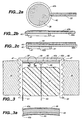
- FIG. 3 is a cross-sectional elevational view depicting a simple embodiment of the microactuator 32.
- the microactuator 32 preferably includes a disk-shaped transducer 45 which is attached to an end of a tube 46.
- the tube 46 is formed with external threads 47 that adapt the tube 46 to be screwed into a fenestration formed through the promontory 18.
- the tube 46 has a diameter of approximately 1.4 mm.
- the fenestration can be made by a mechanical surgical drill, or by present surgical laser techniques.
- the tube 46 may be made out of stainless steel or any other biocompatible metal.
- the transducer 45 is preferably fabricated from a thin circular disk of stress-biased lead lanthanum zirconia titanate (“PLZT”) material. This material is manufactured by Aura Ceramics and sold under the "Rainbow” product designation.
- This PLZT unimorph provides a monolithic structure one side of which is a layer 45a of conventional PLZT material. The other side of the PLZT unimorph is a compositionally reduced layer formed by chemically reducing the oxides in the native PLZT material to produce a conductive cermet layer 45b.
- the conductive cermet layer 45b typically comprises about 30 % of the total disk thickness.
- Removing of the oxide from one side of the unimorph shrinks the conductive cermet layer 45b which bends the whole disk and puts the PLZT layer 45a under compression.
- the PLZT layer 45a is therefore convex while the conductive cermet layer 45b is concave.
- the PLZT layer 45a and the conductive cermet layer 45b are respectively overcoated with a thin metal electrode 48 and a cermet electrode 49.
- the electrodes 48 and 49 may be applied to the transducer 45 in various different ways such as plating, evaporation, metal spraying etc. Application of a potential difference across the electrodes 48 and 49 causes the disk to become either more or less bowed, depending upon the polarity of the applied voltage.
- the electrodes 48 and 49 are made from biocompatible metals such as gold, titanium or platinum.
- the stress-biased transducer 45 is soldered to one end of the tube 46 with indium or with an indium alloy using ultrasonic agitation so the PLZT layer 45a of transducer 45 faces the perilymph fluid 20a.
- dental glue may also be used for securing the transducer 45 to the end of the tube 46.
- the PLZT layer 45a of the transducer 45 and the surrounding end of the tube 46 are then overcoated with a layer 37 of a biocompatible metal using a suitable method such as metal evaporation,
- the layer 37 serves as an electrode for the PLZT layer 45a and also electrically connects the electrode 48 to the surrounding end of the tube 46.
- the conductive cermet layer 45b of the electrode 48 is slightly recessed at its rim by grinding so the conductive cermet layer 45b does not contact the tube 46.
- a gold or precious metal lead 50 wire bonded or attached with conductive epoxy to the cermet electrode 49 within the tube 46, serves as a return lead for the electrode 48.
- Another lead 51 is attached to a surface of the tube 46.
- the leads 50 and 51 are included in the miniature cable 34 which connects the microactuator 32 to signal-processing amplifier 30.
- the layer 37 covering the electrode 48 of the transducer 45 contacts the perilymph fluid 20a.
- the transducer 45 deflects when a voltage is applied across electrodes 48 and 49 thereby generating fluid vibrations within the perilymph fluid 20a at the frequency of the applied voltage.
- the deflections of the transducer 45 are strictly sinusoidal, and the effect of hysteresis in the material is negligible.
- the PLZT layer 45a of the transducer 45 faces the perilymph fluid 20a. This material is biocompatible and poses no problem since it is fully oxidized.
- the conductive cermet layer 45b of the transducer 45 which contains heavy metals, is sealed within the tube 46 by a plug 52 of biocompatible elastomer. Therefore, heavy metal compounds present in the conductive cermet layer 45b have no direct contact with the subject 12.
- the deflection is proportional to a 2 /t 2 , where a is the radius of the disk and t is its thickness.
- the volume of the perilymph fluid 20a displaced by the microactuator 32 is therefore proportional to a 4 , which indicates a very strong dependence on the disk radius a. It is therefore highly advantageous to increase the diameter of the disk-shaped transducer 45 as much as possible.
- the preceding goal is achieved by making the tube 46 as large as possible in diameter, and by minimizing the wall thickness of the tube 46.
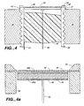
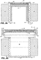
- FIG. 4 A preferred embodiment for the microactuator 32 is illustrated in FIG. 4.
- the embodiment depicted in FIG. 4 differs from the embodiment depicted in FIG. 3 by employing a very thin metallic diaphragm 53 having a rim 54 that is hermetically sealed under slight tension across one end of the threaded tube 46.
- the diaphragm 53 may be formed with a set of small concentric circular corrugations adjacent to the rim 54 to increase the flexibility of the diaphragm 53.
- the diaphragm 53 may be sealed to the tube 46 either by laser beam or electron beam welding, or any other suitable sealing technique.
- the diaphragm 53 may be made out of titanium, stainless steel or aluminum, and may have a thickness of 0.013 mm (0.0005 inches) (in") (12 micron) at the center of the diaphragm 53.
- the rim 54 is somewhat thicker, e.g. 0.076 mm (0.003 in), which provides adequate thickness for welding the diaphragm 53 to the tube 46.
- the diaphragm 53 can be readily fabricated using lithographic etching. Again, the diameter of tube 46 should be as large as can be accommodated by the promontory 18 or the stapes 24.
- the disk-shaped transducer 45 is contained entirely within the tube 46 and is conductively attached to the diaphragm 53 with the conductive cermet layer 45b juxtaposed with the diaphragm 53.
- a very thin layer of conductive epoxy for example of the type used for silicon die attachment in integrated circuit fabrication, may be used for conductively attaching the transducer 45 to the diaphragm 53.
- the threaded tube 46 and diaphragm 53 connect to the cermet electrode 49 for the transducer 45.
- the lead 50 is bonded or attached with conductive epoxy to the electrode 48.
- the transducer 45 is again sealed within the tube 46 by a plug 52 of biocompatible elastomer.
- the diameter of the disk-shaped transducer 45 is slightly less than the respective inner diameters of the thin diaphragm 53 and of the tube 46.
- the diaphragm 53 serves as a support for the disk-shaped transducer 45, deforms conformally with the transducer 45, and at the same time acts as a flexible hinge.
- the rim of disk-shaped transducer 45 is now almost simply supported, rather than clamped.
- a disk simply support at its rim deflects approximately three times as much as a disk having a clamped rim. Consequently, in the embodiment of the microactuator 32 depicted in FIGs.
- the deflection of the transducer 45 and diaphragm 53 is almost three times greater than that of the embodiment depicted in FIG. 3. More significantly, should the disk-shaped transducer 45 break, there can be no contact of the perilymph fluid 20a with heavy metals present in the conductive cermet layer 45b because the transducer 45 is protected by the metal diaphragm 53.
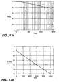
- FIG. 12 depicts several different profilometer measurements of deflection of the flexible diaphragm 53 of the microactuator 32 depicted in FIG. 4.
- a waveform 92 in FIG. 12a records a 0.4 micron deflection measured with a profilometer at the center of the diaphragm 53 in response to the application of a ⁇ 10 volt 1 Hz square wave signal across a 100 micron thick transducer 45.
- Waveforms 94 and 96 in FIGs. 12b and 12c respectively depict corresponding profilometer measurements made near the rim 54 of the diaphragm 53.
- FIG. 12c depicts profilometer measurements of deflection of the flexible diaphragm 53 in response to the application of a ⁇ 10 volt sine wave signal across the transducer 45 having a frequency between 5 and 10 Hz applied across the transducer 45.
- Curves 102 and 104 in FIG. 13 present optical displacement measurements respectively of amplitude, FIG. 13a, and phase, FIG. 13b, relationships between the flexible diaphragm 53 of the microactuator 32 and a sine wave voltage applied across the transducer 45 over a frequency range of 10 to 11,000 Hz.
- FIG. 5 depicts an alternative method for securing the transducer 45 within the tube 46.
- a sleeve 55 either threaded or a split compression sleeve that must be electrically insulated from threaded tube 46, is inserted into the tube 46.
- the sleeve 55 pushes against the disk-shaped transducer 45 thereby urging it into contact with the diaphragm 53.
- the PLZT layer 45a should be juxtaposed with the metal diaphragm 53.
- the disk-shaped transducer 45 is not glued to the diaphragm 53. Similar to the embodiment depicted in FIGs.
- the conductive lead 50 is secured to the cermet electrode 49 and the transducer 45 sealed within the tube 46 by the plug 52.
- the sleeve 55 urges the PLZT layer 45a, that is juxtaposed with the diaphragm 53, into mechanical contact with the diaphragm 53 thereby tensioning the diaphragm 53.
- the sleeve 55 also provides a fixed mechanical reference for electrically induced deflections of the disk-shaped transducer 45, and may also provide an electrical contact to the conductive cermet layer 45b.
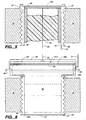
- FIG. 6 Still another embodiment of the microactuator 32 is illustrated in FIG. 6.
- a hydraulic amplifier couples the volumetric displacements created by the transducer 45 to a diaphragm 57.
- the size of the tube 46 which can be implanted in the promontory 18 of the inner ear 17 is limited to about 1.4 mm, which limits the transducer 45 to a maximum diameter of 1.2 mm.
- the PLZT transducer 45 outside the fenestration in the adjacent middle ear cavity 16, its diameter can be almost doubled to about 2.4 mm.
- doubling the diameter of the transducer 45 effectively increases the volumetric displacement for the same applied voltage by a factor of 16 due both to a four fold increase in area of the transducer 45 and to a fourfold increase in deflection of the transducer 45.
- Coupling the motion of the enlarged transducer 45 into the inner ear 17 with a hydraulic amplifier provides a dramatic increase in output.
- the operation of the hydraulic amplifier can be understood as that of a simple piston.
- the threaded tube 46 now has a different cross-sectional shape from the tube 46 respectively depicted in FIGs. 3, 4, 4a and 5.
- a smaller end 46a of the tube 46 contacts the perilymph fluid 20a, while a larger end 46b is located in the middle ear cavity 16.
- the transducer 45 may be used to seal the larger end 46b of the tube 46, preferably very thin metal diaphragms 56 and 57, similar to the diaphragm 53 described above, seal the tube 46 hermetically at both ends 46a and 46b.
- the tube 46 is filled with an incompressible fluid 58 such as silicone oil, saline fluid, etc.
- the fluid 58 must be degassed and free of bubbles so volumetric displacements of the diaphragm 56 are faithfully transmitted to the diaphragm 57. This is done by evacuating the tube 46 and backfilling it through small stainless steel capillaries 59. The capillaries 59 are then sealed with pulsed laser welding which produces an instantaneous seal without bubbles. Alternatively, small copper capillaries 59 may be used for backfilling and then pinched off.
- the disk-shaped transducer 45 is conductively attached to the diaphragm 56 and to the larger end 46b of the tube 46. Alternatively, the transducer 45 may be made small enough to rest entirely on diaphragm 56.
- the conductive cermet layer 45b of the transducer 45 is juxtaposed with the metal diaphragm 56.
- the tube 46 and cermet electrode 49 are preferably grounded.
- the PLZT layer 45a is coated with gold or any other suitable biocompatible material, and the lead 50 attached either through wire bonding or with conductive epoxy.
- a thin layer 36 of a conformal coating may be coated onto the larger end 46b and the transducer 45 to further encapsulate the transducer 45.
- FIG. 7 depicts an alternative embodiment of the microactuator 32 depicted in FIG. 6.
- the microactuator 32 illustrated in FIG. 7 uses a metal cap 60 to press an insulating spacer 61 against the stress-biased PLZT disk-shaped transducer 45. Force thus applied by the spacer 61 urges the transducer 45 against the diaphragm 56 thereby tensioning the diaphragm 57.
- the PLZT layer 45a of the transducer 45 should be juxtaposed with, but not secured to, the diaphragm 56.
- the cap 60 and the cermet electrode 49 are insulated from each other, and respectively connect to leads 51 and 50.
- the transducer 45 may rest on the larger end 46b of tube 46 if necessary. In the embodiment depicted in FIG. 7, it is undesirable to glue the transducer 45 to the tube 46.
- the cap 60 seals the transducer 45 completely thus minimizing exposure of the subject 12 to the conductive cermet layer 45b.
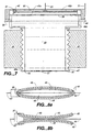
- disk-shaped transducer 45 Since the disk-shaped transducer 45 is stress-biased, curved, and very thin, two disk-shaped transducers 45 can be advantageously arranged to double the amount of excursion for a specified applied voltage without significantly increasing the size of the microactuator 32.
- Two such disk-shaped transducers 45 can be assembled as illustrated in FIG. 8a or FIG. 8b.
- inner electrodes respectively the cermet electrodes 49 in FIG. 8a and the PLZT electrodes 48 in FIG. 8b
- outer electrodes respectively the PLZT electrodes 48 in FIG 8a and the cermet electrodes 49 in FIG.
- rims 35 of the disk-shaped transducers 45 are preferably lapped flat to increase the load surface and to avoid breakage.
- the rims 35 of the disk-shaped transducers 45 of FIG. 8a may be glued together to improve stability.
- FIG. 8a is to be preferred. In principle, it is possible to arrange stacks having more than 2 disk-shaped transducers 45.
- the stacked arrangement for the transducers 45 can be used in the embodiments depicted in FIGs. 5 and 7 as respectively depicted in FIGs. 9a and 9b.
- the disk-shaped transducer 45 are preferably arranged as in FIG. 8a, and are urged against the diaphragm 53 or the diaphragm 56 respectively by a sleeve 55 having a closed end 31 juxtaposed with the stacked transducers 45, or by the cap 60. Note that the closed end 31 of the sleeve 55 must contact the middle of the stacked disk-shaped transducers 45 to obtain the full advantage of the doubling arrangement.
- the sleeve 55 need no longer be insulated from the tube 46.
- the sleeve 55 provides an electrical contact for the outer lead 63 or 50.
- the spacer 61 illustrated in FIG. 7 is omitted from the embodiment depicted in FIG. 9b, and the cap 60 together with the tube 46 provide electrical contacts for the outer lead 63 or 50.
- the lead 51 connects to the inner lead 62 of the stacked transducers 45.
- microactuator 32 implanted into a fenestration formed through the promontory 18 of the inner ear 17 opposite the scala vestibuli.
- the microactuator 32 may also be located and attached in a manner depicted in FIGs. 10, 11, 12 and 13 of the Lesinski et al. patent application.
- Intermediate structures consisting of small barbed hooks, pins, screws etc. may be relatively easily attached to or formed on an exterior surface of the metal diaphragm 53 or 57, and/or the tube 46.
- a diaphragm 53 or 57 can push and pull a bone in the ossicular chain 21, the ear drum 15, the oval window 19, as described in the Lesinski et al. patent application, or the round window 29.
- the phase of the driving signal must be compatible with the phase of the normally functioning vibrations of the ossicular chain 21.
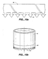
- Stainless steel sheet 65 1 to 3 mils thick, is etched along its border, as depicted in FIG. 10a, to form a pattern of numerous, lithographically defined barbs 64 a few mils wide and 4 to 8 mils long.
- the sheet 65 is then wrapped around and secured to the tube 46, as depicted in FIG. 10b, with the barbs 64 protruding away from the tube 46. When pressed against tissue, the barbs 64 attach the sheet 65 together with the tube 46 to the tissue.
- the strength of attachment is determined by the length and size of the barbs 64.
- the length of the barbs 64 is preferably selected so the microactuator 32 can be removed with minimal damage to the tissue.
- a larger diameter microactuator 32 does not form part of the claimed invention and is described by way of background only. It is approximately 8-10 mm in diameter and may be implanted into the external auditory canal 14 in a subject 12 having a damaged ear drum 15. Such a microactuator 32 must include an external protective membrane to seal the microactuator 32 within the external auditory canal 14. The larger diameter transducer 45 of such a microactuator 32 compensates for the larger displacement needed at the ear drum 15, while the external protective membrane, which seals the microactuator 32 within the external auditory canal 14, permits activities such as playing contact sports, swimming, showering, etc.
- the microactuator 32 is useful as a hearing aid 10 only if it generates sufficiently large vibrations in the perilymph fluid 20a in response to low voltage signals and with very low power dissipation thus permitting the microactuator 32 to be powered for 5 to 6 years by an implantable battery.
- the disk-shaped transducer 45 responds electrically as a capacitor. Consequently, power dissipation in the transducer 45 is due to charging and discharging the capacitance. Therefore, power dissipation increases with increasing frequency.
- the dielectric constant of stress-biased PLZT is about 1700. Therefore the capacitance of a stress-biased PLZT disk 1.2 mm in diameter and 100 microns thick is about 240 pico-Farads ("pF").
- Such a transducer supported at its rim produces approximately a 0.2 micron PTP displacement for a voltage change of 10 V (or ⁇ 5 V).
- Such a displacement in the perilymph fluid 20a which for a 1,000 Hz sinusoidal voltage supplied to the transducer 45 requires a 2.4 microampere current, corresponds to a sound level approaching 100 dB.
- the transducer 45 in accordance with the present invention in response to the application of a sinusoidal electric signal at a frequency of 1000 Hz, displaces at least 1.0 ⁇ 10 -4 microliters of the perilymph fluid 20a for an electrical power input to the microactuator 32 of approximately 25 microwatts, i.e. less than 50 microwatts.
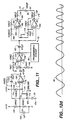
- FIG. 11 depicts an amplifier circuit, referred to by the general reference character 70, adapted for driving any of the disclosed embodiments of the microactuator 32.
- the amplifier 70 includes a low-noise 2N5196 JFET 72 which has a gate 112 that is coupled to the electrode 42b to receive the signal produced by the microphone 28.
- a drain 114 of the JFET 72 is coupled through a 100 K ⁇ resistor 116 to a +3.0 V supply voltage from a battery not depicted in any of the FIGs.
- the drain 114 of the JFET 72 is also coupled to a non-inverting input 118 of a Max 491CPD micropower intermediate stage operational amplifier 74 included in the amplifier 70.
- An inverting input 122 of the operational amplifier 74 is coupled to common terminals of a series connected 20 M ⁇ resistor 124 and 40 M ⁇ resistor 126. Coupling of another terminal of the resistor 124 to the +3.0 V battery supply voltage and another terminal of the resistor 126 to circuit ground provides the inverting input 122 of the operational amplifier 74 with a bias voltage.
- a 1 ⁇ F capacitor 128 is connected in parallel with the resistor 126.
- a parallel connected 40 M ⁇ resistor 132 and 50 pF capacitor 134 are connected between an output 136 of the operational amplifier 74 and the gate 112 of the JFET 72. The resistor 132 and the capacitor 134 cause the combined JFET 72 and operational amplifier 74 to operate as a charge-sensitive input stage for the amplifier 70.
- a 470 pF capacitor 142 couples an output signal from the output 136 of the operational amplifier 74 to a non-inverting input 144 of a second Max 491CPD micropower operational amplifier 76.
- a 1 M ⁇ resistor 146 connects the non-inverting input 144 to circuit ground.
- An inverting input 152 of the operational amplifier 76 is coupled to common terminals of a series connected 10 M ⁇ resistor 154 and 1 M ⁇ resistor 156. Coupling of another terminal of the resistor 154 to an output 158 of the operational amplifier 76 and another terminal of the resistor 156 to circuit ground establishes a fixed gain for the operational amplifier 76.
- a 470 pF capacitor 162 couples an output signal from the output 158 of the operational amplifier 76 in parallel both to a non-inverting input 164 of a third Max 491CPD micropower operational amplifier 82, and through a 9.09 M ⁇ resistor 166 to an inverting input 168 of a fourth Max 491CPD micropower operational amplifier 84.
- An inverting input 172 of the operational amplifier 84 is coupled to common terminals of a series connected 10 M ⁇ resistor 174 and 1 M ⁇ resistor 176. Coupling of another terminal of the resistor 174 to an output 178 of the operational amplifier 82 and another terminal of the resistor 176 to circuit ground establishes a fixed gain for the operational amplifier 82.
- a typical output signal from a 1.0 cm 2 PVDF microphone 28 exposed to a 100 dB sound level is approximately 3.0 mV PTP. Consequently, the gain required for the amplifier 70 to reproduce such a 100 dB sound level in the perilymph fluid 20a using microactuator 32 is approximately 4000.
- the amplifier 70 depicted in FIG. 11 draws approximately 20 uA of current. Therefore, using an implantable battery having a capacity of 1.0 ampere hour ("AH") to power the hearing aid 10 16 hours per day provides an anticipated battery life of more than 5 years.
- the circuit depicted in FIG. 11 has no special provisions for signal processing, either in analog or digital form, such as appear to be required for the hearing aid 10. Rather, the amplifier 70 merely demonstrates that adequate battery life is feasible for the signal-processing amplifier 30 needed to power the operation of the microactuator 32. Special signal processing circuits, such as those described by Killion in "The K-Amp Hearing Aid: An Attempt to Present High Fidelity for Persons With Impaired Hearing," American Journal of Audiology, vol. 2, no. 2, July 1993, may be used to process and amplify the signal from the microphone 28 for driving the microactuator 32. Accordingly, frequency amplification characteristics of the signal-processing amplifier 30 can be "customized" to meet the unique requirements of each subject's particular hearing loss.
- the signal-processing amplifier 30 For programming the operation of the signal-processing amplifier 30, for example setting the amplification, selecting passbands or their degree of emphasis, etc., the signal-processing amplifier 30 preferably uses a scheme similar to that employed in programming a computer modem. That is, a programmable transmitter, not illustrated in any of the FIGs., held close to the microphone 28 produces a pre-defined sequence of acoustical tones, for example tones analogous to the Dual-Tone Multi-Frequency ("DTMF”) signals used for touch-tone telephone dialing.
- DTMF Dual-Tone Multi-Frequency
- the programming circuit 86 appropriately modifies signal processing characteristics of the signal-processing amplifier 30.
- an audiologist uses the transmitter to adjust the hearing aid 10 for optimum performance.
- the subject 12 uses a simplified, hand-held, battery operated transmitter to set the hearing aid 10 into a sleep mode, or to adjust the operation of the hearing aid 10 to the prevailing sound environment.
- Such acoustical tones for programming the hearing aid 10 may be transmitted at higher than audio frequencies, since both the PVDF microphone 28 and the signal-processing amplifier 30 are capable of accepting and processing such signals.
- the hearing aid 10 is adaptable for implantation in a subject 12 with either conductive hearing loss or sensorineural hearing impairment. It is particularly advantageous over conventional hearing aids in treating subjects with conductive hearing loss from external or middle ear abnormalities, since the external and middle ear are bypassed with the fully implantable hearing aid 10. In subjects with sensorineural hearing impairment, the hearing aid 10 is advantageous over a conventional hearing aid because the hearing aid 10 does not obstruct the normal conduction of sound to the inner ear, but rather acts as a booster to amplify sound directly into the cochlea.
- FIG. 14 consisting of FIGs. 14a and 14b, depicts disposing an oval-shaped transducer 45 at an oblique angle with respect to a longitudinal axis 202 of the tube 46.
- the transducer 45 may be disposed at an oblique angle either by having a tapered end 204 on the tube 46 as depicted in FIG.
- Disposing the transducer 45 at an oblique angle with respect to the longitudinal axis 202 increases the area of the transducer 45. Increasing the area of the transducer 45 is advantageous because, as set forth previously, the quantity of fluid displaced by the microactuator 32 increases rapidly as transducer area increases.
- a microactuator 32 for use in the present invention may be fabricated using other types of piezoelectric systems.
- a microactuator 32 for use in the present invention may be fabricated using a metal laminated unimorph 212, depicted in FIG. 15.
- the laminated unimorph 212 consists of a plate 214 of piezoelectric material, e.g. lead zirconia titanate ("PZT"), onto which is deposited a conductive metallic layer 216.
- PZT lead zirconia titanate
- the piezoelectric plate 214 may be lapped down to a thickness of 1 mil (0,0254 mm), and then coated with a thin chromium layer 218 onto which is plated a thin nickel layer 219.
- the thin nickel layer 219 stresses the piezoelectric plate 214 thereby mimicking the stress-bias of the conductive cermet layer 45b in the preferred PLZT unimorph transducer 45.
- a metal laminated unimorph 212 may be fabricated by applying a thin layer 219 of a memory alloy, such as 5 to 20 microns of Nitinol, Ni-Ti-Cu or Cu-Zn-Al, to the piezoelectric plate 214. After a layer 219 of such material has been applied to the piezoelectric plate 214, heating or cooling the memory alloy establishes a phase in which the memory alloy layer 219 applies compressive or tensile stress to the plate 214. As is apparent to those skilled in the art of memory alloys, hysteresis in a phase transition of a memory alloy maintains that stress upon removal of the heating or cooling.
- a memory alloy such as 5 to 20 microns of Nitinol, Ni-Ti-Cu or Cu-Zn-Al
- the laminated unimorph 212 stressed biased either with the plated nickel layer 219 or with the memory alloy layer 219 appears to be inferior to the preferred stress-biased PLZT unimorph transducer 45, it is possible that the performance of the laminated unimorph 212 might approach that of the preferred unimorph transducer 45.
- a disk-shaped bimorph 222 illustrated in FIG. 16, might also be substituted for the preferred transducer 45.
- the bimorph 222 consists of two lapped plates 224 and 226 of a piezoelectric material, such as PZT, 1 mil (0,0254 mm) thick.
- the plates 224 and 226 are bonded to each other by a layer 228 of electrically conductive material such as a metal. If the piezoelectric plates 224 and 226 of the bimorph 222 are properly poled as indicated by the "+" and "-" symbols in FIG. 16, applying an alternating current voltage from the conductive middle layer 228 to both outer surfaces 232a and 232b causes the bimorph 222 to alternatively bend back and forth similar to the preferred stress-biased PLZT unimorph transducer 45.
Claims (12)
- Hörhilfe (10) zum Implantieren in eine Person, die sowohl eine Paukenhöhle, in der sich eine Gehörknöchelchenkette bestehend aus Hammer, Amboss und Steigbügel befindet, der in einer Steigbügelplatte endet, als auch ein fluidgefülltes Innenohr hat, das von einer knöchernen Ohrkapsel mit einem Promontorium, einem ovalen Fenster, an dem die Steigbügelplatte befestigt ist, und einem runden Fenster umschlossen ist; wobei die genannte Hörhilfe Folgendes umfasst:dadurch gekennzeichnet, dass der Wandler so konfiguriert ist, dass er Vibrationen erzeugt, die proportional zur Verdrängung, als Reaktion auf ein sinusförmiges verarbeitetes elektrisches Signal mit einer Frequenz von 1000 Hz, von wenigstens 1,0 x 10⁻⁴ Mikrolitern des Fluids für einen elektrischen Energieeingang von weniger als 50 Mikrowatt sind, und wobei der Mikroaktuator ein starres röhrenförmiges Element (46) mit einer Länge von höchstens 2 mm aufweist, das so gestaltet ist, dass es starr in eine Fensterung implantiert werden kann, die die Ohrkapsel durchbohrt.ein Mikrofon (28) zum subkutanen Implantieren in die Person und zum Erzeugen eines elektrischen Signals als Reaktion auf das Auftreffen von Schallwellen auf die Person;Signalverarbeitungsmittel (30) zum Empfangen des elektrischen Signals von dem Mikrofon und zum Verarbeiten und Weiterleiten eines verarbeiteten elektrischen Signals, wobei das genannte Signalverarbeitungsmittel ebenfalls für eine Implantation in die Person gestaltet ist;eine Batterie zum Zuführen von elektrischer Energie zu dem genannten Signalverarbeitungsmittel, wobei die genannte Batterie ebenfalls für eine Implantation in die Person gestaltet ist; undeinen Mikroaktuator (32) zum Implantieren in die Person an einem Ort, von dem ein Wandler (45) in dem genannten Mikroaktuator mechanisch Vibrationen in dem Fluid im Innenohr der Person erzeugt, wobei der Wandler mit dem Signalverarbeitungsmittel gekoppelt ist, um das verarbeitete elektrische Signal von dem genannten Signalverarbeitungsmittel zu empfangen und als Reaktion darauf die Vibrationen in dem im Innenohr vorhandenen Fluid zu erzeugen, so dass die Hörhilfe nach der Implantation des Mikroaktuators Hörnervenfasern stimuliert, wobei die Person eine solche Stimulation als Schall wahrnimmt,
- Hörhilfe nach Anspruch 1, bei der der Wandler eine erste Platte aus einem piezoelektrischen Material aufweist, das an dem röhrenförmigen Element (46) befestigt ist, wobei das piezoelektrische Material elektrisch mit dem Signalverarbeitungsmittel verbunden ist, um das verarbeitete elektrische Signal von dem genannten Verarbeitungsmittel zu empfangen.
- Hörhilfe nach Anspruch 2, bei der das genannte Mikrofon eine PVDF-Folie aufweist, die mit biokompatiblen Elektroden überzogen ist.
- Hörhilfe nach Anspruch 3, bei der die genannte PVDF-Folie von einem flexiblen Ring getragen wird, der die genannte PVDF-Folie umgibt und spannt.
- Hörhilfe nach Anspruch 2, bei der in das genannte Mikrofon ein fluidgefülltes Hydrophon mikrogearbeitet ist.
- Hörhilfe nach Anspruch 2, bei der das genannte Mikrofon zum Implantieren an einem Ort distal von dem genannten Mikroaktuator gestaltet ist, um dadurch akustische Kopplung zwischen dem genannten Mikrofon und dem genannten Mikroaktuator zu reduzieren.
- Hörhilfe nach Anspruch 2, ferner umfassend Montagemittel zum Befestigen des genannten Mikroaktuators in einer Fensterung, die durch das Promontorium ausgebildet ist, so dass der Wandler nach der Implantation direkten Kontakt mit Fluid im Innenohr erhält.
- Hörhilfe nach Anspruch 7, wobei das Montagemittel ein Gewinde auf einer Außenfläche des Rohres hat, so dass der Mikroaktuator in die Fensterung geschraubt werden kann.
- Hörhilfe nach Anspruch 2, wobei eine Außenfläche des Rohrs und des Wandlers, die für einen direkten Kontakt des Fluids mit dem Innenohr gestaltet ist, aus einem elektronisch leitenden Material gebildet sind und eine Elektrode für den Wandler bilden.
- Hörhilfe nach Anspruch 2, wobei die erste Platte aus vorgespanntem PLZT-Material eines Rainbow-Keramiktyps gebildet ist, das so bearbeitet ist, dass eine Seitenfläche davon in seiner Zusammensetzung reduziert wurde, um ein Material mit einer Cermet-Zusammensetzung zu erhalten, so dass die erste Platte ein monolithisches Unimorph bildet.
- Hörhilfe nach Anspruch 2, wobei die erste Platte ein laminiertes Metallunimorph ist.
- Hörhilfe nach Anspruch 2, wobei die erste Platte ein Bimorph ist.
Applications Claiming Priority (3)
| Application Number | Priority Date | Filing Date | Title |
|---|---|---|---|
| US08/532,398 US5772575A (en) | 1995-09-22 | 1995-09-22 | Implantable hearing aid |
| US532398 | 1995-09-22 | ||
| PCT/US1996/015087 WO1997011575A1 (en) | 1995-09-22 | 1996-09-19 | Implantable hearing aid |
Publications (3)
| Publication Number | Publication Date |
|---|---|
| EP0873668A1 EP0873668A1 (de) | 1998-10-28 |
| EP0873668A4 EP0873668A4 (de) | 2004-03-31 |
| EP0873668B1 true EP0873668B1 (de) | 2005-05-04 |
Family
ID=24121613
Family Applications (1)
| Application Number | Title | Priority Date | Filing Date |
|---|---|---|---|
| EP96935881A Expired - Lifetime EP0873668B1 (de) | 1995-09-22 | 1996-09-19 | Implantierbares hörhilfegerät |
Country Status (7)
| Country | Link |
|---|---|
| US (1) | US5772575A (de) |
| EP (1) | EP0873668B1 (de) |
| JP (1) | JP3710483B2 (de) |
| AU (1) | AU7366496A (de) |
| CA (1) | CA2232553C (de) |
| DE (1) | DE69634700T2 (de) |
| WO (1) | WO1997011575A1 (de) |
Families Citing this family (145)
| Publication number | Priority date | Publication date | Assignee | Title |
|---|---|---|---|---|
| US5772575A (en) * | 1995-09-22 | 1998-06-30 | S. George Lesinski | Implantable hearing aid |
| JP2000504913A (ja) * | 1996-02-15 | 2000-04-18 | アーマンド ピー ニューカーマンス | 改良された生体共存型トランスデューサー |
| US6161046A (en) * | 1996-04-09 | 2000-12-12 | Maniglia; Anthony J. | Totally implantable cochlear implant for improvement of partial and total sensorineural hearing loss |
| DE19738587C1 (de) * | 1997-09-03 | 1999-05-27 | Implex Gmbh | Anordnung zum Einstellen und Fixieren der Relativlage zweier Elemente eines aktiven oder passiven Hör-Implantats |
| DE19840212C2 (de) * | 1998-09-03 | 2001-08-02 | Implex Hear Tech Ag | Wandleranordnung für teil- oder vollimplantierbare Hörgeräte |
| US6473651B1 (en) | 1999-03-02 | 2002-10-29 | Advanced Bionics Corporation | Fluid filled microphone balloon to be implanted in the middle ear |
| US6687547B2 (en) * | 1999-09-14 | 2004-02-03 | Medtronic, Inc. | Method and apparatus for communicating with an implantable medical device with DTMF tones |
| US6554761B1 (en) | 1999-10-29 | 2003-04-29 | Soundport Corporation | Flextensional microphones for implantable hearing devices |
| US6629922B1 (en) | 1999-10-29 | 2003-10-07 | Soundport Corporation | Flextensional output actuators for surgically implantable hearing aids |
| DE10018361C2 (de) | 2000-04-13 | 2002-10-10 | Cochlear Ltd | Mindestens teilimplantierbares Cochlea-Implantat-System zur Rehabilitation einer Hörstörung |
| DE10018360C2 (de) | 2000-04-13 | 2002-10-10 | Cochlear Ltd | Mindestens teilimplantierbares System zur Rehabilitation einer Hörstörung |
| DE10018334C1 (de) | 2000-04-13 | 2002-02-28 | Implex Hear Tech Ag | Mindestens teilimplantierbares System zur Rehabilitation einer Hörstörung |
| US6517476B1 (en) | 2000-05-30 | 2003-02-11 | Otologics Llc | Connector for implantable hearing aid |
| US6648813B2 (en) | 2000-06-17 | 2003-11-18 | Alfred E. Mann Foundation For Scientific Research | Hearing aid system including speaker implanted in middle ear |
| US6572531B2 (en) * | 2000-06-17 | 2003-06-03 | Alfred E. Mann Foundation For Scientific Reseach | Implantable middle ear implant |
| DE10031832C2 (de) | 2000-06-30 | 2003-04-30 | Cochlear Ltd | Hörgerät zur Rehabilitation einer Hörstörung |
| CA2411782A1 (en) * | 2000-06-30 | 2002-01-17 | Cochlear Limited | Cochlear implant |
| DE10046938A1 (de) | 2000-09-21 | 2002-04-25 | Implex Ag Hearing Technology I | Mindestens teilimplantierbares Hörsystem mit direkter mechanischer Stimulation eines lymphatischen Raums des Innenohres |
| DE10062236C2 (de) * | 2000-12-14 | 2003-11-27 | Phonak Ag Staefa | Fixationselement für ein implantierbares Mikrofon |
| US6542777B1 (en) * | 2001-01-19 | 2003-04-01 | Advanced Bionics Corporation | Spiral shield for a flexible high-Q implantable inductively coupled device |
| AU2002252676A1 (en) * | 2001-04-12 | 2002-10-28 | Otologics Llc | Hearing aid with internal acoustic middle ear transducer |
| US7616771B2 (en) * | 2001-04-27 | 2009-11-10 | Virginia Commonwealth University | Acoustic coupler for skin contact hearing enhancement devices |
| US6537201B1 (en) | 2001-09-28 | 2003-03-25 | Otologics Llc | Implantable hearing aid with improved sealing |
| AU2002342150A1 (en) | 2001-10-30 | 2003-05-12 | George S. Lesinski | Implantation method for a hearing aid microactuator implanted into the cochlea |
| US6620094B2 (en) | 2001-11-21 | 2003-09-16 | Otologics, Llc | Method and apparatus for audio input to implantable hearing aids |
| US6712754B2 (en) | 2002-02-26 | 2004-03-30 | Otologics Llc | Method and system for positioning implanted hearing aid actuators |
| US6879693B2 (en) * | 2002-02-26 | 2005-04-12 | Otologics, Llc. | Method and system for external assessment of hearing aids that include implanted actuators |
| US20030163021A1 (en) * | 2002-02-26 | 2003-08-28 | Miller Douglas Alan | Method and system for external assessment of hearing aids that include implanted actuators |
| US7197152B2 (en) * | 2002-02-26 | 2007-03-27 | Otologics Llc | Frequency response equalization system for hearing aid microphones |
| US20030161481A1 (en) * | 2002-02-26 | 2003-08-28 | Miller Douglas Alan | Method and system for external assessment of hearing aids that include implanted actuators |
| US7033313B2 (en) | 2002-12-11 | 2006-04-25 | No. 182 Corporate Ventures Ltd. | Surgically implantable hearing aid |
| EP1435757A1 (de) * | 2002-12-30 | 2004-07-07 | Andrzej Zarowski | Implantat für eine Knochenwand des Innenohres |
| DE10301723B3 (de) * | 2003-01-15 | 2004-09-16 | Med-El Elektromedizinische Geräte GmbH | Implantierbarer elektromechanischer Wandler |
| US7442164B2 (en) * | 2003-07-23 | 2008-10-28 | Med-El Elektro-Medizinische Gerate Gesellschaft M.B.H. | Totally implantable hearing prosthesis |
| US7252005B2 (en) * | 2003-08-22 | 2007-08-07 | Alfred E. Mann Foundation For Scientific Research | System and apparatus for sensing pressure in living organisms and inanimate objects |
| JP2005111631A (ja) * | 2003-10-09 | 2005-04-28 | Star Micronics Co Ltd | Nc自動旋盤 |
| US7580754B2 (en) * | 2003-11-14 | 2009-08-25 | Cochlear Limited | Implantable acoustic sensor |
| US8412342B2 (en) | 2003-11-14 | 2013-04-02 | Hearworks Pty, Limited | Implantable acoustic sensor |
| US7137946B2 (en) * | 2003-12-11 | 2006-11-21 | Otologics Llc | Electrophysiological measurement method and system for positioning an implantable, hearing instrument transducer |
| WO2005060306A1 (en) * | 2003-12-12 | 2005-06-30 | Medical Research Products-B, Inc. | Surgical instrument set and procedure for implanting sound transducer proximate to patient's outer ear canal |
| US20050218052A1 (en) * | 2004-04-06 | 2005-10-06 | Houts Christina M | Abient noise power generator |
| US7778434B2 (en) * | 2004-05-28 | 2010-08-17 | General Hearing Instrument, Inc. | Self forming in-the-ear hearing aid with conical stent |
| US20060098833A1 (en) * | 2004-05-28 | 2006-05-11 | Juneau Roger P | Self forming in-the-ear hearing aid |
| US7955249B2 (en) * | 2005-10-31 | 2011-06-07 | Earlens Corporation | Output transducers for hearing systems |
| US8295523B2 (en) | 2007-10-04 | 2012-10-23 | SoundBeam LLC | Energy delivery and microphone placement methods for improved comfort in an open canal hearing aid |
| US7668325B2 (en) | 2005-05-03 | 2010-02-23 | Earlens Corporation | Hearing system having an open chamber for housing components and reducing the occlusion effect |
| US7867160B2 (en) | 2004-10-12 | 2011-01-11 | Earlens Corporation | Systems and methods for photo-mechanical hearing transduction |
| US8142344B2 (en) * | 2005-02-25 | 2012-03-27 | Advanced Bionics Ag | Fully implantable hearing aid system |
| US7290953B2 (en) * | 2005-03-08 | 2007-11-06 | Everyday Innovations Inc. | Pocketable note holder with writing instrument |
| CA2600396C (en) * | 2005-03-22 | 2014-09-02 | S. George Lesinski | Implanting a therapeutic appliance into the cochlea |
| US7582052B2 (en) * | 2005-04-27 | 2009-09-01 | Otologics, Llc | Implantable hearing aid actuator positioning |
| US8836513B2 (en) | 2006-04-28 | 2014-09-16 | Proteus Digital Health, Inc. | Communication system incorporated in an ingestible product |
| US8802183B2 (en) | 2005-04-28 | 2014-08-12 | Proteus Digital Health, Inc. | Communication system with enhanced partial power source and method of manufacturing same |
| US8912908B2 (en) | 2005-04-28 | 2014-12-16 | Proteus Digital Health, Inc. | Communication system with remote activation |
| CN101287411B (zh) | 2005-04-28 | 2013-03-06 | 普罗秋斯生物医学公司 | 药物信息系统及其用途 |
| AU2006283905B2 (en) * | 2005-08-22 | 2009-12-03 | 3Win N.V. | A combined set comprising a vibrator actuator and an implantable device |
| US7753838B2 (en) * | 2005-10-06 | 2010-07-13 | Otologics, Llc | Implantable transducer with transverse force application |
| US8014871B2 (en) * | 2006-01-09 | 2011-09-06 | Cochlear Limited | Implantable interferometer microphone |
| US7801319B2 (en) | 2006-05-30 | 2010-09-21 | Sonitus Medical, Inc. | Methods and apparatus for processing audio signals |
| US7720542B2 (en) * | 2006-07-17 | 2010-05-18 | Med-El Elektromedizinische Geraete Gmbh | Remote sensing and actuation of fluid in cranial implants |
| WO2008112578A1 (en) | 2007-03-09 | 2008-09-18 | Proteus Biomedical, Inc. | In-body device having a deployable antenna |
| SE0701242L (sv) * | 2007-05-24 | 2008-12-02 | Cochlear Ltd | Vibrator |
| DK2208367T3 (da) | 2007-10-12 | 2017-11-13 | Earlens Corp | Multifunktionssystem og fremgangsmåde til integreret lytning og kommunikation med støjannullering og feedback-håndtering |
| KR100931209B1 (ko) | 2007-11-20 | 2009-12-10 | 경북대학교 산학협력단 | 간편 설치가 가능한 정원창 구동 진동 트랜스듀서 및 이를이용한 이식형 보청기 |
| US7822479B2 (en) * | 2008-01-18 | 2010-10-26 | Otologics, Llc | Connector for implantable hearing aid |
| DE102008009284B4 (de) † | 2008-02-15 | 2009-10-22 | Siemens Audiologische Technik Gmbh | Wasserresistentes Hörgerät |
| CN101978518A (zh) * | 2008-03-21 | 2011-02-16 | 日本碍子株式会社 | 压电/电致伸缩元件及其制造方法 |
| US8526641B2 (en) * | 2008-03-31 | 2013-09-03 | Cochlear Limited | Customizable mass arrangements for bone conduction devices |
| US8019431B2 (en) * | 2008-06-02 | 2011-09-13 | University Of Washington | Enhanced signal processing for cochlear implants |
| WO2009155361A1 (en) | 2008-06-17 | 2009-12-23 | Earlens Corporation | Optical electro-mechanical hearing devices with combined power and signal architectures |
| KR101568452B1 (ko) | 2008-06-17 | 2015-11-20 | 이어렌즈 코포레이션 | 개별 전원과 신호 구성요소들을 구비한 광 전자-기계적 청력 디바이스 |
| US8396239B2 (en) | 2008-06-17 | 2013-03-12 | Earlens Corporation | Optical electro-mechanical hearing devices with combined power and signal architectures |
| EP2313003B1 (de) | 2008-08-13 | 2016-08-03 | Proteus Digital Health, Inc. | Einnehmbarer schaltkreis |
| US8301260B2 (en) * | 2008-08-13 | 2012-10-30 | Daglow Terry D | Method of implanting a medical implant to treat hearing loss in a patient, devices for faciliting implantation of such devices, and medical implants for treating hearing loss |
| DK3509324T3 (da) | 2008-09-22 | 2023-10-02 | Earlens Corp | Balancerede armaturindretninger og fremgangsmåder til at høre |
| WO2010111403A2 (en) | 2009-03-25 | 2010-09-30 | Proteus Biomedical, Inc. | Probablistic pharmacokinetic and pharmacodynamic modeling |
| DE102009014770A1 (de) * | 2009-03-25 | 2010-09-30 | Cochlear Ltd., Lane Cove | Schwingungserzeuger |
| USRE48797E1 (en) | 2009-03-25 | 2021-10-26 | Cochlear Limited | Bone conduction device having a multilayer piezoelectric element |
| SG175388A1 (en) | 2009-04-28 | 2011-12-29 | Proteus Biomedical Inc | Highly reliable ingestible event markers and methods for using the same |
| WO2010132331A2 (en) | 2009-05-12 | 2010-11-18 | Proteus Biomedical, Inc. | Ingestible event markers comprising an ingestible component |
| DK2438768T3 (en) | 2009-06-05 | 2016-06-06 | Earlens Corp | Optically coupled acoustically mellemøreimplantatindretning |
| US9544700B2 (en) | 2009-06-15 | 2017-01-10 | Earlens Corporation | Optically coupled active ossicular replacement prosthesis |
| US8401214B2 (en) | 2009-06-18 | 2013-03-19 | Earlens Corporation | Eardrum implantable devices for hearing systems and methods |
| EP2443773B1 (de) | 2009-06-18 | 2017-01-11 | Earlens Corporation | Systeme für optisch gekoppeltes cochleamplantat |
| EP2446645B1 (de) | 2009-06-22 | 2020-05-06 | Earlens Corporation | Optisch gekoppelte knochenleitungssysteme und -verfahren |
| BRPI1016075A2 (pt) | 2009-06-22 | 2016-05-10 | SoundBeam LLC | dispositivo para transmitir som para um ouvido de um usuário e métodos associados. |
| US8845705B2 (en) | 2009-06-24 | 2014-09-30 | Earlens Corporation | Optical cochlear stimulation devices and methods |
| US8715154B2 (en) | 2009-06-24 | 2014-05-06 | Earlens Corporation | Optically coupled cochlear actuator systems and methods |
| US8774930B2 (en) * | 2009-07-22 | 2014-07-08 | Vibrant Med-El Hearing Technology Gmbh | Electromagnetic bone conduction hearing device |
| EP2484125B1 (de) | 2009-10-02 | 2015-03-11 | Sonitus Medical, Inc. | Intraorale vorrichtung zur klangübertragung über eine knochenleitung |
| CN104581592B (zh) | 2009-11-24 | 2019-01-29 | Med-El电气医疗器械有限公司 | 用于听觉系统的可植入麦克风 |
| SG184494A1 (en) | 2010-04-07 | 2012-11-29 | Proteus Biomedical Inc | Miniature ingestible device |
| US20130223028A1 (en) * | 2010-07-29 | 2013-08-29 | Proteus Digital Health, Inc. | Hybrid housing for implantable medical device |
| CA2806540A1 (en) * | 2010-08-03 | 2012-02-09 | Sonitus Medical, Inc. | Implantable piezoelectric polymer film microphone |
| AU2011295787B2 (en) | 2010-09-03 | 2015-11-19 | Med-El Elektromedizinische Geraete Gmbh | Middle ear implantable microphone |
| US9155887B2 (en) | 2010-10-19 | 2015-10-13 | Cochlear Limited | Relay interface for connecting an implanted medical device to an external electronics device |
| WO2012055436A1 (en) * | 2010-10-27 | 2012-05-03 | Advanced Bionics Ag | Implantable actuator for hearing stimulation |
| US9131323B2 (en) | 2010-11-03 | 2015-09-08 | Cochlear Limited | Hearing prosthesis having an implantable actuator system |
| EP2642983A4 (de) | 2010-11-22 | 2014-03-12 | Proteus Digital Health Inc | Einnehmbare vorrichtung mit einem pharmazeutischen produkt |
| DK2656639T3 (da) | 2010-12-20 | 2020-06-29 | Earlens Corp | Anatomisk tilpasset øregangshøreapparat |
| EP2663231A1 (de) * | 2011-01-10 | 2013-11-20 | Advanced Bionics AG | System und verfahren zur in-situ-auswertung eines aktuators eines implantierbaren hörgeräts |
| US20120245408A1 (en) * | 2011-03-22 | 2012-09-27 | University Of Washington Through Its Center For Commercialization | Methods and systems for improving actuator performance by reducing tensile stresses in piezoelectric thin films |
| US9107013B2 (en) | 2011-04-01 | 2015-08-11 | Cochlear Limited | Hearing prosthesis with a piezoelectric actuator |
| US9313589B2 (en) * | 2011-07-01 | 2016-04-12 | Cochlear Limited | Method and system for configuration of a medical device that stimulates a human physiological system |
| US9756874B2 (en) | 2011-07-11 | 2017-09-12 | Proteus Digital Health, Inc. | Masticable ingestible product and communication system therefor |
| WO2015112603A1 (en) | 2014-01-21 | 2015-07-30 | Proteus Digital Health, Inc. | Masticable ingestible product and communication system therefor |
| US9554222B2 (en) | 2011-12-07 | 2017-01-24 | Cochlear Limited | Electromechanical transducer with mechanical advantage |
| US8828002B2 (en) | 2012-01-20 | 2014-09-09 | Otokinetics Inc. | Fenestration burr |
| AU2013252520B2 (en) * | 2012-04-26 | 2015-06-11 | Med-El Elektromedizinische Geraete Gmbh | Non-pressure sensitive implantable microphone |
| US20130303835A1 (en) * | 2012-05-10 | 2013-11-14 | Otokinetics Inc. | Microactuator |
| BR112015001388A2 (pt) | 2012-07-23 | 2017-07-04 | Proteus Digital Health Inc | técnicas para fabricar marcadores de eventos ingeríveis que compreendem um componente ingerível |
| ES2683193T3 (es) | 2012-08-20 | 2018-09-25 | Better Hearing S.A.A.K. Technologies Ltd | Dispositivo de audífono |
| US9167362B2 (en) | 2012-09-13 | 2015-10-20 | Otokinetics Inc. | Implantable receptacle for a hearing aid component |
| ES2683709T3 (es) | 2012-10-18 | 2018-09-27 | Proteus Digital Health, Inc. | Aparato, sistema, y procedimiento para optimizar de manera adaptativa la disipación de energía y la energía de difusión en una fuente de energía para un dispositivo de comunicación |
| US11149123B2 (en) | 2013-01-29 | 2021-10-19 | Otsuka Pharmaceutical Co., Ltd. | Highly-swellable polymeric films and compositions comprising the same |
| JP5941240B2 (ja) | 2013-03-15 | 2016-06-29 | プロテウス デジタル ヘルス, インコーポレイテッド | 金属検出器装置、システム、および方法 |
| US9796576B2 (en) | 2013-08-30 | 2017-10-24 | Proteus Digital Health, Inc. | Container with electronically controlled interlock |
| US10084880B2 (en) | 2013-11-04 | 2018-09-25 | Proteus Digital Health, Inc. | Social media networking based on physiologic information |
| US10034103B2 (en) | 2014-03-18 | 2018-07-24 | Earlens Corporation | High fidelity and reduced feedback contact hearing apparatus and methods |
| WO2016011044A1 (en) | 2014-07-14 | 2016-01-21 | Earlens Corporation | Sliding bias and peak limiting for optical hearing devices |
| US9924276B2 (en) | 2014-11-26 | 2018-03-20 | Earlens Corporation | Adjustable venting for hearing instruments |
| US11051543B2 (en) | 2015-07-21 | 2021-07-06 | Otsuka Pharmaceutical Co. Ltd. | Alginate on adhesive bilayer laminate film |
| US10348891B2 (en) | 2015-09-06 | 2019-07-09 | Deborah M. Manchester | System for real time, remote access to and adjustment of patient hearing aid with patient in normal life environment |
| EP3888564A1 (de) | 2015-10-02 | 2021-10-06 | Earlens Corporation | Angepasste gehörgangvorrichtung zur arzneimittelabgabe |
| US10178483B2 (en) | 2015-12-30 | 2019-01-08 | Earlens Corporation | Light based hearing systems, apparatus, and methods |
| US10492010B2 (en) | 2015-12-30 | 2019-11-26 | Earlens Corporations | Damping in contact hearing systems |
| US11350226B2 (en) | 2015-12-30 | 2022-05-31 | Earlens Corporation | Charging protocol for rechargeable hearing systems |
| WO2017139891A1 (en) * | 2016-02-17 | 2017-08-24 | Dalhousie University | Piezoelectric inertial actuator |
| US10842531B2 (en) | 2016-06-22 | 2020-11-24 | Cochlear Limited | Electrode insertion tool with additional functionality |
| US10477332B2 (en) | 2016-07-18 | 2019-11-12 | Cochlear Limited | Integrity management of an implantable device |
| EP3487393A4 (de) | 2016-07-22 | 2020-01-15 | Proteus Digital Health, Inc. | Elektromagnetische erfassung und detektion von einnehmbaren ereignismarkern |
| US11285314B2 (en) | 2016-08-19 | 2022-03-29 | Cochlear Limited | Advanced electrode array insertion |
| CN112738700A (zh) | 2016-09-09 | 2021-04-30 | 伊尔兰斯公司 | 智能镜系统和方法 |
| CA3041041A1 (en) | 2016-10-26 | 2018-05-03 | Proteus Digital Health, Inc. | Methods for manufacturing capsules with ingestible event markers |
| US11432084B2 (en) | 2016-10-28 | 2022-08-30 | Cochlear Limited | Passive integrity management of an implantable device |
| WO2018093733A1 (en) | 2016-11-15 | 2018-05-24 | Earlens Corporation | Improved impression procedure |
| US10897677B2 (en) | 2017-03-24 | 2021-01-19 | Cochlear Limited | Shock and impact management of an implantable device during non use |
| US11223912B2 (en) | 2017-07-21 | 2022-01-11 | Cochlear Limited | Impact and resonance management |
| US10292675B2 (en) * | 2017-10-10 | 2019-05-21 | Ingen1, L.L.C. | Stethoscope |
| WO2019173470A1 (en) | 2018-03-07 | 2019-09-12 | Earlens Corporation | Contact hearing device and retention structure materials |
| WO2019199680A1 (en) | 2018-04-09 | 2019-10-17 | Earlens Corporation | Dynamic filter |
| US11223913B2 (en) | 2018-10-08 | 2022-01-11 | Nanoear Corporation, Inc. | Compact hearing aids |
| AU2019356768A1 (en) * | 2018-10-08 | 2021-04-22 | Nanoear Corporation, Inc. | Compact hearing aids |
| DE102018126387A1 (de) * | 2018-10-23 | 2020-04-23 | Tdk Electronics Ag | Schallwandler und Verfahren zum Betrieb des Schallwandlers |
| CN115103283B (zh) * | 2022-05-17 | 2023-03-14 | 中国矿业大学 | 一种用于辅助佩戴耳膜激振式人工中耳的装置 |
Family Cites Families (72)
| Publication number | Priority date | Publication date | Assignee | Title |
|---|---|---|---|---|
| US3557775A (en) * | 1963-12-27 | 1971-01-26 | Jack Lawrence Mahoney | Method of implanting a hearing aid |
| US3346704A (en) * | 1963-12-27 | 1967-10-10 | Jack L Mahoney | Means for aiding hearing |
| US3594514A (en) * | 1970-01-02 | 1971-07-20 | Medtronic Inc | Hearing aid with piezoelectric ceramic element |
| US3712962A (en) * | 1971-04-05 | 1973-01-23 | J Epley | Implantable piezoelectric hearing aid |
| US3764748A (en) * | 1972-05-19 | 1973-10-09 | J Branch | Implanted hearing aids |
| GB1440724A (en) * | 1972-07-18 | 1976-06-23 | Fredrickson J M | Implantable electromagnetic hearing aid |
| US3882285A (en) * | 1973-10-09 | 1975-05-06 | Vicon Instr Company | Implantable hearing aid and method of improving hearing |
| FR2307357A1 (fr) * | 1975-04-11 | 1976-11-05 | Thomson Csf | Structure monolithique de stockage de charges electriques, procede de mise en charge de cette structure et composants electroniques d'application |
| USRE31031E (en) * | 1977-03-16 | 1982-09-14 | Implantable electronic hearing aid | |
| US4063048A (en) * | 1977-03-16 | 1977-12-13 | Kissiah Jr Adam M | Implantable electronic hearing aid |
| DE2825233A1 (de) * | 1977-06-21 | 1979-01-04 | Georges Ducommun | Hoergeraet |
| US4078160A (en) * | 1977-07-05 | 1978-03-07 | Motorola, Inc. | Piezoelectric bimorph or monomorph bender structure |
| JPS5544239A (en) * | 1978-09-22 | 1980-03-28 | Rion Co Ltd | Converter for hearing-aid of implanted type |
| NL7903964A (nl) * | 1979-05-21 | 1980-11-25 | Philips Nv | Pieezo-elektrisch lichaam voor een elektromechanisch omvormingselement. |
| US4284856A (en) * | 1979-09-24 | 1981-08-18 | Hochmair Ingeborg | Multi-frequency system and method for enhancing auditory stimulation and the like |
| JPS56131979A (en) * | 1980-03-19 | 1981-10-15 | Hitachi Ltd | Piezoelectric material for transparent vibrator and transparent vibrator |
| US4419995A (en) * | 1981-09-18 | 1983-12-13 | Hochmair Ingeborg | Single channel auditory stimulation system |
| US4419495A (en) * | 1981-09-21 | 1983-12-06 | The Dow Chemical Company | Epoxy resin powder coatings having low gloss |
| SE431705B (sv) * | 1981-12-01 | 1984-02-20 | Bo Hakansson | Koppling, foretredesvis avsedd for mekanisk overforing av ljudinformation till skallbenet pa en horselskadad person |
| JPS58147400U (ja) * | 1982-03-30 | 1983-10-04 | 工業技術院長 | 植込形補聴器用駆動トランスジユ−サ |
| US4756312A (en) * | 1984-03-22 | 1988-07-12 | Advanced Hearing Technology, Inc. | Magnetic attachment device for insertion and removal of hearing aid |
| US4617913A (en) * | 1984-10-24 | 1986-10-21 | The University Of Utah | Artificial hearing device and method |
| US4850962A (en) * | 1984-12-04 | 1989-07-25 | Medical Devices Group, Inc. | Implantable hearing aid and method of improving hearing |
| US4729366A (en) * | 1984-12-04 | 1988-03-08 | Medical Devices Group, Inc. | Implantable hearing aid and method of improving hearing |
| AU5481786A (en) * | 1985-03-20 | 1986-09-25 | Hochmair, E.S. | Transcutaneous power and signal transmission system |
| US4606329A (en) * | 1985-05-22 | 1986-08-19 | Xomed, Inc. | Implantable electromagnetic middle-ear bone-conduction hearing aid device |
| US5015225A (en) * | 1985-05-22 | 1991-05-14 | Xomed, Inc. | Implantable electromagnetic middle-ear bone-conduction hearing aid device |
| US4612915A (en) * | 1985-05-23 | 1986-09-23 | Xomed, Inc. | Direct bone conduction hearing aid device |
| US4817607A (en) * | 1986-03-07 | 1989-04-04 | Richards Medical Company | Magnetic ossicular replacement prosthesis |
| US4800884A (en) * | 1986-03-07 | 1989-01-31 | Richards Medical Company | Magnetic induction hearing aid |
| GB2188290B (en) * | 1986-03-26 | 1989-11-29 | Williams Professor John Ffowcs | Waterborne vessel |
| NL8602043A (nl) * | 1986-08-08 | 1988-03-01 | Forelec N V | Werkwijze voor het verpakken van een implantaat, bijvoorbeeld een electronisch circuit, verpakking en implantaat. |
| US4726099A (en) * | 1986-09-17 | 1988-02-23 | American Cyanamid Company | Method of making piezoelectric composites |
| SU1551371A1 (ru) * | 1987-01-29 | 1990-03-23 | 1-Й Московский Медицинский Институт Им.И.М.Сеченова | Протез слуховых косточек |
| US5091820A (en) * | 1987-03-18 | 1992-02-25 | Tdk Corporation | Ceramic piezoelectric element with electrodes formed by reduction |
| US4943750A (en) * | 1987-05-20 | 1990-07-24 | Massachusetts Institute Of Technology | Electrostatic micromotor |
| US4817609A (en) * | 1987-09-11 | 1989-04-04 | Resound Corporation | Method for treating hearing deficiencies |
| US4985926A (en) * | 1988-02-29 | 1991-01-15 | Motorola, Inc. | High impedance piezoelectric transducer |
| DE3821970C1 (de) * | 1988-06-29 | 1989-12-14 | Ernst-Ludwig Von Dr. 8137 Berg De Wallenberg-Pachaly | |
| US5085628A (en) * | 1988-09-09 | 1992-02-04 | Storz Instrument Company | Implantable hearing aid coupler device |
| US4988333A (en) * | 1988-09-09 | 1991-01-29 | Storz Instrument Company | Implantable middle ear hearing aid system and acoustic coupler therefor |
| US4957478A (en) * | 1988-10-17 | 1990-09-18 | Maniglia Anthony J | Partially implantable hearing aid device |
| US5015224A (en) * | 1988-10-17 | 1991-05-14 | Maniglia Anthony J | Partially implantable hearing aid device |
| US4908509A (en) * | 1988-10-27 | 1990-03-13 | Massachusetts Institute Of Technology | Traction and reaction force microsensor |
| WO1990007915A1 (de) * | 1989-01-20 | 1990-07-26 | Klaus Schumann | Gehörprothesen für das mittelohr von lebewesen, insbesondere menschen |
| DE3918086C1 (de) * | 1989-06-02 | 1990-09-27 | Hortmann Gmbh, 7449 Neckartenzlingen, De | |
| US4928264A (en) * | 1989-06-30 | 1990-05-22 | The United States Of America As Represented By The Secretary Of The Navy | Noise-suppressing hydrophones |
| US5095904A (en) * | 1989-09-08 | 1992-03-17 | Cochlear Pty. Ltd. | Multi-peak speech procession |
| US5271397A (en) * | 1989-09-08 | 1993-12-21 | Cochlear Pty. Ltd. | Multi-peak speech processor |
| US5061282A (en) * | 1989-10-10 | 1991-10-29 | Jacobs Jared J | Cochlear implant auditory prosthesis |
| US5033999A (en) * | 1989-10-25 | 1991-07-23 | Mersky Barry L | Method and apparatus for endodontically augmenting hearing |
| US5498226A (en) * | 1990-03-05 | 1996-03-12 | Lenkauskas; Edmundas | Totally implanted hearing device |
| US4999819A (en) * | 1990-04-18 | 1991-03-12 | The Pennsylvania Research Corporation | Transformed stress direction acoustic transducer |
| JP2905257B2 (ja) * | 1990-04-25 | 1999-06-14 | 本田技研工業株式会社 | 船外機の弾性マウントを介した連結構造 |
| JP2761970B2 (ja) * | 1990-07-09 | 1998-06-04 | 住友特殊金属株式会社 | 透明スピーカー |
| US5176620A (en) * | 1990-10-17 | 1993-01-05 | Samuel Gilman | Hearing aid having a liquid transmission means communicative with the cochlea and method of use thereof |
| US5191559A (en) * | 1990-12-05 | 1993-03-02 | The United States Of America As Represented By The Secretary Of The Navy | Piezoelectric ceramic hydrostatic sound sensor |
| DE4104358A1 (de) * | 1991-02-13 | 1992-08-20 | Implex Gmbh | Implantierbares hoergeraet zur anregung des innenohres |
| US5282858A (en) * | 1991-06-17 | 1994-02-01 | American Cyanamid Company | Hermetically sealed implantable transducer |
| US5338287A (en) * | 1991-12-23 | 1994-08-16 | Miller Gale W | Electromagnetic induction hearing aid device |
| US5276657A (en) * | 1992-02-12 | 1994-01-04 | The Pennsylvania Research Corporation | Metal-electroactive ceramic composite actuators |
| US5408534A (en) * | 1992-03-05 | 1995-04-18 | Knowles Electronics, Inc. | Electret microphone assembly, and method of manufacturer |
| FR2688132B1 (fr) * | 1992-03-06 | 1994-05-27 | Tem Audio Implant System | Prothese passive pour chaine tympano-ossiculaire. |
| DE4210235C1 (de) * | 1992-03-28 | 1993-11-18 | Heinz Kurz | Gehörknöchelprothese |
| US5306299A (en) * | 1992-09-21 | 1994-04-26 | Smith & Nephew Richards, Inc. | Middle ear prosthesis |
| US5344387A (en) * | 1992-12-23 | 1994-09-06 | Lupin Alan J | Cochlear implant |
| US5531787A (en) * | 1993-01-25 | 1996-07-02 | Lesinski; S. George | Implantable auditory system with micromachined microsensor and microactuator |
| US5471721A (en) * | 1993-02-23 | 1995-12-05 | Research Corporation Technologies, Inc. | Method for making monolithic prestressed ceramic devices |
| JP3151644B2 (ja) * | 1993-03-08 | 2001-04-03 | 日本碍子株式会社 | 圧電/電歪膜型素子 |
| US5554096A (en) * | 1993-07-01 | 1996-09-10 | Symphonix | Implantable electromagnetic hearing transducer |
| US5456654A (en) * | 1993-07-01 | 1995-10-10 | Ball; Geoffrey R. | Implantable magnetic hearing aid transducer |
| US5772575A (en) * | 1995-09-22 | 1998-06-30 | S. George Lesinski | Implantable hearing aid |
-
1995
- 1995-09-22 US US08/532,398 patent/US5772575A/en not_active Expired - Lifetime
-
1996
- 1996-09-19 EP EP96935881A patent/EP0873668B1/de not_active Expired - Lifetime
- 1996-09-19 DE DE69634700T patent/DE69634700T2/de not_active Expired - Lifetime
- 1996-09-19 CA CA002232553A patent/CA2232553C/en not_active Expired - Fee Related
- 1996-09-19 JP JP51291397A patent/JP3710483B2/ja not_active Expired - Fee Related
- 1996-09-19 AU AU73664/96A patent/AU7366496A/en not_active Abandoned
- 1996-09-19 WO PCT/US1996/015087 patent/WO1997011575A1/en active IP Right Grant
Also Published As
| Publication number | Publication date |
|---|---|
| EP0873668A1 (de) | 1998-10-28 |
| CA2232553C (en) | 2007-12-04 |
| JP3710483B2 (ja) | 2005-10-26 |
| AU7366496A (en) | 1997-04-09 |
| DE69634700T2 (de) | 2006-01-19 |
| CA2232553A1 (en) | 1997-03-27 |
| US5772575A (en) | 1998-06-30 |
| JPH11511625A (ja) | 1999-10-05 |
| DE69634700D1 (de) | 2005-06-09 |
| WO1997011575A1 (en) | 1997-03-27 |
| EP0873668A4 (de) | 2004-03-31 |
Similar Documents
| Publication | Publication Date | Title |
|---|---|---|
| EP0873668B1 (de) | Implantierbares hörhilfegerät | |
| EP0963683B1 (de) | Verbesserte mikrophone für implantierbares hörhilfegerät | |
| US6005955A (en) | Middle ear transducer | |
| US5707338A (en) | Stapes vibrator | |
| AU710983B2 (en) | Improved biocompatible transducers | |
| US8150083B2 (en) | Piezoelectric bone conduction device having enhanced transducer stroke | |
| US5997466A (en) | Implantable hearing system having multiple transducers | |
| US10129660B2 (en) | Implantable middle ear transducer having improved frequency response | |
| AU2006205655B2 (en) | Hearing implant | |
| US5879283A (en) | Implantable hearing system having multiple transducers | |
| US7524278B2 (en) | Hearing aid system and transducer with hermetically sealed housing | |
| EP2533738A1 (de) | Hörhilfe mit einem intracochleabetätiger | |
| WO1999008480A2 (en) | Middle ear transducer | |
| CA2479822C (en) | Improved microphones for an implantable hearing aid | |
| EP1596629A2 (de) | Elektronikmodul für ein implantierbares Hörgerät | |
| CA2246281C (en) | Improved biocompatible transducers |
Legal Events
| Date | Code | Title | Description |
|---|---|---|---|
| PUAI | Public reference made under article 153(3) epc to a published international application that has entered the european phase |
Free format text: ORIGINAL CODE: 0009012 |
|
| 17P | Request for examination filed |
Effective date: 19980319 |
|
| AK | Designated contracting states |
Kind code of ref document: A1 Designated state(s): DE ES FR GB IT |
|
| A4 | Supplementary search report drawn up and despatched |
Effective date: 20040212 |
|
| 17Q | First examination report despatched |
Effective date: 20040405 |
|
| GRAP | Despatch of communication of intention to grant a patent |
Free format text: ORIGINAL CODE: EPIDOSNIGR1 |
|
| GRAS | Grant fee paid |
Free format text: ORIGINAL CODE: EPIDOSNIGR3 |
|
| GRAA | (expected) grant |
Free format text: ORIGINAL CODE: 0009210 |
|
| AK | Designated contracting states |
Kind code of ref document: B1 Designated state(s): DE ES FR GB IT |
|
| PG25 | Lapsed in a contracting state [announced via postgrant information from national office to epo] |
Ref country code: IT Free format text: LAPSE BECAUSE OF FAILURE TO SUBMIT A TRANSLATION OF THE DESCRIPTION OR TO PAY THE FEE WITHIN THE PRE;WARNING: LAPSES OF ITALIAN PATENTS WITH EFFECTIVE DATE BEFORE 2007 MAY HAVE OCCURRED AT ANY TIME BEFORE 2007. THE CORRECT EFFECTIVE DATE MAY BE DIFFERENT FROM THE ONE RECORDED.SCRIBED TIME-LIMIT Effective date: 20050504 |
|
| REG | Reference to a national code |
Ref country code: GB Ref legal event code: FG4D |
|
| REF | Corresponds to: |
Ref document number: 69634700 Country of ref document: DE Date of ref document: 20050609 Kind code of ref document: P |
|
| PG25 | Lapsed in a contracting state [announced via postgrant information from national office to epo] |
Ref country code: ES Free format text: LAPSE BECAUSE OF FAILURE TO SUBMIT A TRANSLATION OF THE DESCRIPTION OR TO PAY THE FEE WITHIN THE PRESCRIBED TIME-LIMIT Effective date: 20050815 |
|
| PLBE | No opposition filed within time limit |
Free format text: ORIGINAL CODE: 0009261 |
|
| STAA | Information on the status of an ep patent application or granted ep patent |
Free format text: STATUS: NO OPPOSITION FILED WITHIN TIME LIMIT |
|
| ET | Fr: translation filed | ||
| 26N | No opposition filed |
Effective date: 20060207 |
|
| PGFP | Annual fee paid to national office [announced via postgrant information from national office to epo] |
Ref country code: GB Payment date: 20130923 Year of fee payment: 18 Ref country code: FR Payment date: 20130920 Year of fee payment: 18 |
|
| PGFP | Annual fee paid to national office [announced via postgrant information from national office to epo] |
Ref country code: DE Payment date: 20131016 Year of fee payment: 18 |
|
| REG | Reference to a national code |
Ref country code: DE Ref legal event code: R119 Ref document number: 69634700 Country of ref document: DE |
|
| GBPC | Gb: european patent ceased through non-payment of renewal fee |
Effective date: 20140919 |
|
| REG | Reference to a national code |
Ref country code: FR Ref legal event code: ST Effective date: 20150529 |
|
| PG25 | Lapsed in a contracting state [announced via postgrant information from national office to epo] |
Ref country code: GB Free format text: LAPSE BECAUSE OF NON-PAYMENT OF DUE FEES Effective date: 20140919 Ref country code: DE Free format text: LAPSE BECAUSE OF NON-PAYMENT OF DUE FEES Effective date: 20150401 |
|
| PG25 | Lapsed in a contracting state [announced via postgrant information from national office to epo] |
Ref country code: FR Free format text: LAPSE BECAUSE OF NON-PAYMENT OF DUE FEES Effective date: 20140930 |