US11432084B2 - Passive integrity management of an implantable device - Google Patents
Passive integrity management of an implantable device Download PDFInfo
- Publication number
- US11432084B2 US11432084B2 US15/336,910 US201615336910A US11432084B2 US 11432084 B2 US11432084 B2 US 11432084B2 US 201615336910 A US201615336910 A US 201615336910A US 11432084 B2 US11432084 B2 US 11432084B2
- Authority
- US
- United States
- Prior art keywords
- component
- housing
- transducer
- seismic mass
- piezoelectric
- Prior art date
- Legal status (The legal status is an assumption and is not a legal conclusion. Google has not performed a legal analysis and makes no representation as to the accuracy of the status listed.)
- Active, expires
Links
- 210000000988 bone and bone Anatomy 0.000 claims abstract description 117
- 239000000306 component Substances 0.000 claims description 395
- 230000006835 compression Effects 0.000 claims description 43
- 238000007906 compression Methods 0.000 claims description 43
- 238000000034 method Methods 0.000 claims description 41
- 230000001133 acceleration Effects 0.000 claims description 36
- 238000013016 damping Methods 0.000 claims description 22
- 230000009471 action Effects 0.000 claims description 13
- 230000005611 electricity Effects 0.000 claims description 13
- 238000005452 bending Methods 0.000 claims description 6
- 238000004891 communication Methods 0.000 claims description 4
- 230000004044 response Effects 0.000 claims description 4
- 239000008358 core component Substances 0.000 claims description 2
- 238000007667 floating Methods 0.000 claims description 2
- 230000000717 retained effect Effects 0.000 claims description 2
- 230000003068 static effect Effects 0.000 claims description 2
- 210000001519 tissue Anatomy 0.000 claims 1
- 239000000463 material Substances 0.000 description 50
- 229920003266 Leaf® Polymers 0.000 description 20
- 230000005291 magnetic effect Effects 0.000 description 15
- 230000035939 shock Effects 0.000 description 15
- 238000010586 diagram Methods 0.000 description 13
- 230000002829 reductive effect Effects 0.000 description 11
- 210000003477 cochlea Anatomy 0.000 description 9
- 239000007943 implant Substances 0.000 description 8
- 210000000883 ear external Anatomy 0.000 description 7
- 210000000959 ear middle Anatomy 0.000 description 7
- 210000003625 skull Anatomy 0.000 description 6
- 239000011248 coating agent Substances 0.000 description 5
- 238000000576 coating method Methods 0.000 description 5
- 210000000613 ear canal Anatomy 0.000 description 5
- 210000002768 hair cell Anatomy 0.000 description 5
- 238000002513 implantation Methods 0.000 description 5
- 238000013519 translation Methods 0.000 description 5
- 230000014616 translation Effects 0.000 description 5
- 230000008859 change Effects 0.000 description 4
- 230000002939 deleterious effect Effects 0.000 description 4
- 230000007246 mechanism Effects 0.000 description 4
- 230000005236 sound signal Effects 0.000 description 4
- PCTMTFRHKVHKIS-BMFZQQSSSA-N (1s,3r,4e,6e,8e,10e,12e,14e,16e,18s,19r,20r,21s,25r,27r,30r,31r,33s,35r,37s,38r)-3-[(2r,3s,4s,5s,6r)-4-amino-3,5-dihydroxy-6-methyloxan-2-yl]oxy-19,25,27,30,31,33,35,37-octahydroxy-18,20,21-trimethyl-23-oxo-22,39-dioxabicyclo[33.3.1]nonatriaconta-4,6,8,10 Chemical compound C1C=C2C[C@@H](OS(O)(=O)=O)CC[C@]2(C)[C@@H]2[C@@H]1[C@@H]1CC[C@H]([C@H](C)CCCC(C)C)[C@@]1(C)CC2.O[C@H]1[C@@H](N)[C@H](O)[C@@H](C)O[C@H]1O[C@H]1/C=C/C=C/C=C/C=C/C=C/C=C/C=C/[C@H](C)[C@@H](O)[C@@H](C)[C@H](C)OC(=O)C[C@H](O)C[C@H](O)CC[C@@H](O)[C@H](O)C[C@H](O)C[C@](O)(C[C@H](O)[C@H]2C(O)=O)O[C@H]2C1 PCTMTFRHKVHKIS-BMFZQQSSSA-N 0.000 description 3
- 208000000781 Conductive Hearing Loss Diseases 0.000 description 3
- 206010010280 Conductive deafness Diseases 0.000 description 3
- 210000000860 cochlear nerve Anatomy 0.000 description 3
- 208000023563 conductive hearing loss disease Diseases 0.000 description 3
- 230000003247 decreasing effect Effects 0.000 description 3
- 210000003027 ear inner Anatomy 0.000 description 3
- 238000004519 manufacturing process Methods 0.000 description 3
- 210000005036 nerve Anatomy 0.000 description 3
- 238000001356 surgical procedure Methods 0.000 description 3
- 206010011878 Deafness Diseases 0.000 description 2
- 206010011891 Deafness neurosensory Diseases 0.000 description 2
- 208000009966 Sensorineural Hearing Loss Diseases 0.000 description 2
- 238000010521 absorption reaction Methods 0.000 description 2
- 230000006378 damage Effects 0.000 description 2
- 239000012530 fluid Substances 0.000 description 2
- 210000003128 head Anatomy 0.000 description 2
- 231100000888 hearing loss Toxicity 0.000 description 2
- 230000010370 hearing loss Effects 0.000 description 2
- 208000016354 hearing loss disease Diseases 0.000 description 2
- 230000000670 limiting effect Effects 0.000 description 2
- 230000008569 process Effects 0.000 description 2
- 230000000284 resting effect Effects 0.000 description 2
- 230000002441 reversible effect Effects 0.000 description 2
- 231100000879 sensorineural hearing loss Toxicity 0.000 description 2
- 208000023573 sensorineural hearing loss disease Diseases 0.000 description 2
- 238000003462 Bender reaction Methods 0.000 description 1
- 241000878128 Malleus Species 0.000 description 1
- 208000003028 Stuttering Diseases 0.000 description 1
- RTAQQCXQSZGOHL-UHFFFAOYSA-N Titanium Chemical compound [Ti] RTAQQCXQSZGOHL-UHFFFAOYSA-N 0.000 description 1
- 230000004913 activation Effects 0.000 description 1
- 210000003484 anatomy Anatomy 0.000 description 1
- 230000008901 benefit Effects 0.000 description 1
- 210000004556 brain Anatomy 0.000 description 1
- 210000004027 cell Anatomy 0.000 description 1
- 230000008602 contraction Effects 0.000 description 1
- 230000008878 coupling Effects 0.000 description 1
- 238000010168 coupling process Methods 0.000 description 1
- 238000005859 coupling reaction Methods 0.000 description 1
- 238000001514 detection method Methods 0.000 description 1
- 238000011161 development Methods 0.000 description 1
- 230000000694 effects Effects 0.000 description 1
- 230000008030 elimination Effects 0.000 description 1
- 238000003379 elimination reaction Methods 0.000 description 1
- 239000003302 ferromagnetic material Substances 0.000 description 1
- 230000006870 function Effects 0.000 description 1
- 230000005484 gravity Effects 0.000 description 1
- 210000001785 incus Anatomy 0.000 description 1
- 210000002331 malleus Anatomy 0.000 description 1
- 229910052751 metal Inorganic materials 0.000 description 1
- 239000002184 metal Substances 0.000 description 1
- 230000037361 pathway Effects 0.000 description 1
- 230000000149 penetrating effect Effects 0.000 description 1
- 230000008447 perception Effects 0.000 description 1
- 210000004049 perilymph Anatomy 0.000 description 1
- 229920001296 polysiloxane Polymers 0.000 description 1
- 230000009467 reduction Effects 0.000 description 1
- 230000002207 retinal effect Effects 0.000 description 1
- 238000004513 sizing Methods 0.000 description 1
- 239000007787 solid Substances 0.000 description 1
- 241000894007 species Species 0.000 description 1
- 210000001323 spiral ganglion Anatomy 0.000 description 1
- 210000001050 stape Anatomy 0.000 description 1
- 230000000638 stimulation Effects 0.000 description 1
- 238000003860 storage Methods 0.000 description 1
- 239000010936 titanium Substances 0.000 description 1
- 229910052719 titanium Inorganic materials 0.000 description 1
- 238000012546 transfer Methods 0.000 description 1
- 210000003454 tympanic membrane Anatomy 0.000 description 1
Images


Classifications
-
- H—ELECTRICITY
- H04—ELECTRIC COMMUNICATION TECHNIQUE
- H04R—LOUDSPEAKERS, MICROPHONES, GRAMOPHONE PICK-UPS OR LIKE ACOUSTIC ELECTROMECHANICAL TRANSDUCERS; DEAF-AID SETS; PUBLIC ADDRESS SYSTEMS
- H04R25/00—Deaf-aid sets, i.e. electro-acoustic or electro-mechanical hearing aids; Electric tinnitus maskers providing an auditory perception
- H04R25/60—Mounting or interconnection of hearing aid parts, e.g. inside tips, housings or to ossicles
- H04R25/604—Mounting or interconnection of hearing aid parts, e.g. inside tips, housings or to ossicles of acoustic or vibrational transducers
- H04R25/606—Mounting or interconnection of hearing aid parts, e.g. inside tips, housings or to ossicles of acoustic or vibrational transducers acting directly on the eardrum, the ossicles or the skull, e.g. mastoid, tooth, maxillary or mandibular bone, or mechanically stimulating the cochlea, e.g. at the oval window
-
- H—ELECTRICITY
- H04—ELECTRIC COMMUNICATION TECHNIQUE
- H04R—LOUDSPEAKERS, MICROPHONES, GRAMOPHONE PICK-UPS OR LIKE ACOUSTIC ELECTROMECHANICAL TRANSDUCERS; DEAF-AID SETS; PUBLIC ADDRESS SYSTEMS
- H04R17/00—Piezoelectric transducers; Electrostrictive transducers
- H04R17/005—Piezoelectric transducers; Electrostrictive transducers using a piezoelectric polymer
-
- H—ELECTRICITY
- H04—ELECTRIC COMMUNICATION TECHNIQUE
- H04R—LOUDSPEAKERS, MICROPHONES, GRAMOPHONE PICK-UPS OR LIKE ACOUSTIC ELECTROMECHANICAL TRANSDUCERS; DEAF-AID SETS; PUBLIC ADDRESS SYSTEMS
- H04R23/00—Transducers other than those covered by groups H04R9/00 - H04R21/00
- H04R23/02—Transducers using more than one principle simultaneously
-
- H—ELECTRICITY
- H04—ELECTRIC COMMUNICATION TECHNIQUE
- H04R—LOUDSPEAKERS, MICROPHONES, GRAMOPHONE PICK-UPS OR LIKE ACOUSTIC ELECTROMECHANICAL TRANSDUCERS; DEAF-AID SETS; PUBLIC ADDRESS SYSTEMS
- H04R2217/00—Details of magnetostrictive, piezoelectric, or electrostrictive transducers covered by H04R15/00 or H04R17/00 but not provided for in any of their subgroups
- H04R2217/01—Non-planar magnetostrictive, piezoelectric or electrostrictive benders
-
- H—ELECTRICITY
- H04—ELECTRIC COMMUNICATION TECHNIQUE
- H04R—LOUDSPEAKERS, MICROPHONES, GRAMOPHONE PICK-UPS OR LIKE ACOUSTIC ELECTROMECHANICAL TRANSDUCERS; DEAF-AID SETS; PUBLIC ADDRESS SYSTEMS
- H04R2460/00—Details of hearing devices, i.e. of ear- or headphones covered by H04R1/10 or H04R5/033 but not provided for in any of their subgroups, or of hearing aids covered by H04R25/00 but not provided for in any of its subgroups
- H04R2460/13—Hearing devices using bone conduction transducers
Definitions
- Hearing loss which may be due to many different causes, is generally of two types: conductive and sensorineural.
- Sensorineural hearing loss is due to the absence or destruction of the hair cells in the cochlea that transduce sound signals into nerve impulses.
- Various hearing prostheses are commercially available to provide individuals suffering from sensorineural hearing loss with the ability to perceive sound.
- cochlear implants use an electrode array implanted in the cochlea of a recipient to bypass the mechanisms of the ear. More specifically, an electrical stimulus is provided via the electrode array to the auditory nerve, thereby causing a hearing percept.
- Conductive hearing loss occurs when the normal mechanical pathways that provide sound to hair cells in the cochlea are impeded, for example, by damage to the ossicular chain or the ear canal. Individuals suffering from conductive hearing loss may retain some form of residual hearing because the hair cells in the cochlea may remain undamaged.
- Hearing aids rely on principles of air conduction to transmit acoustic signals to the cochlea.
- a hearing aid typically uses an arrangement positioned in the recipient's ear canal or on the outer ear to amplify a sound received by the outer ear of the recipient. This amplified sound reaches the cochlea causing motion of the perilymph and stimulation of the auditory nerve.
- Bone conduction devices In contrast to hearing aids, which rely primarily on the principles of air conduction, certain types of hearing prostheses commonly referred to as bone conduction devices, convert a received sound into vibrations. The vibrations are transferred through the skull to the cochlea causing generation of nerve impulses, which result in the perception of the received sound. Bone conduction devices are suitable to treat a variety of types of hearing loss and may be suitable for individuals who cannot derive sufficient benefit from acoustic hearing aids, cochlear implants, etc., or for individuals who suffer from stuttering problems.
- a prosthetic medical device comprising: a housing; and a piezoelectric component, wherein the piezoelectric component is supported in the housing via at least one spring.
- a component of a bone conduction device comprising: a housing; and a transducer-seismic mass assembly, wherein the component is configured to enable permanent shock-proofing of the assembly beyond that which results from damping.
- a component of a transcutaneous bone conduction device comprising: a housing; and a transducer-seismic mass assembly including a piezoelectric component, wherein the transducer-seismic mass assembly of the transcutaneous bone conduction device is configured to translate in its entirety within the when the housing is closed.
- a method comprising: obtaining a component of a medical device prosthesis including a piezoelectric bender; operating the component in a first mechanical state such that the piezoelectric bender bends in a manner that at least one of consumes or generates electricity, wherein the component is configured to experience an acceleration of 100 Gs in the first mechanical state in both directions normal to a plane of extension of the piezoelectric bender and subsequently operate in the first mechanical state.
- FIG. 1 is a perspective view of an exemplary bone conduction device in which at least some embodiments can be implemented
- FIG. 2 is a schematic diagram conceptually illustrating a passive transcutaneous bone conduction device
- FIG. 3 is a schematic diagram conceptually illustrating an active transcutaneous bone conduction device in accordance with at least some exemplary embodiments
- FIG. 4 is a schematic diagram of an outer portion of an implantable component of a bone conduction device
- FIG. 5 is a schematic diagram of a cross-section of an exemplary implantable component of a bone conduction device
- FIG. 6 is a schematic diagram of a cross-section of the exemplary implantable component of FIG. 5 in operation
- FIG. 7 is a schematic diagram of a cross-section of the exemplary implantable component of FIG. 5 in a failure mode
- FIG. 8 is a schematic diagram of a cross-section of an exemplary embodiment that prevents the failure mode conceptually represented in FIG. 7 ;
- FIG. 9 is a schematic diagram of a portion of the cross-section of the exemplary embodiment depicted in FIG. 8 ;
- FIG. 10-14B are schematic diagrams depicting features of the embodiment of FIG. 7 and variations thereof;
- FIGS. 15 and 16 depict an exemplary embodiment of an alternate implementation of the teachings detailed herein;
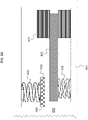
- FIG. 17 depicts an exemplary graph containing data associated with the exemplary embodiment of FIGS. 15 and 16 ;
- FIGS. 18 and 19 are schematic diagrams depicting various alternative embodiments of the teachings detailed herein;
- FIGS. 20 and 21 are schematic diagrams depicting an alternate embodiment according to the teachings detailed herein;
- FIGS. 22 and 23 are schematic diagrams depicting an alternative embodiment according to the teachings detailed herein;
- FIG. 24 presents an exemplary flowchart for an exemplary method according to an exemplary embodiment.
- FIGS. 25 and 26 are schematic diagrams of alternative embodiments according to an exemplary embodiment.
- Embodiments herein are described primarily in terms of a bone conduction device, such as an active transcutaneous bone conduction device. However, it is noted that the teachings detailed herein and/or variations thereof are also applicable to a cochlear implant and/or a middle ear implant. Accordingly, any disclosure herein of teachings utilized with an active transcutaneous bone conduction device also corresponds to a disclosure of utilizing those teachings with respect to a cochlear implant and utilizing those teachings with respect to a middle ear implant. Moreover, at least some exemplary embodiments of the teachings detailed herein are also applicable to a passive transcutaneous bone conduction device.
- FIG. 1 is a perspective view of a bone conduction device 100 in which embodiments may be implemented.
- the recipient has an outer ear 101 , a middle ear 102 , and an inner ear 103 .
- Elements of outer ear 101 , middle ear 102 , and inner ear 103 are described below, followed by a description of bone conduction device 100 .
- outer ear 101 comprises an auricle 105 and an ear canal 106 .
- a sound wave or acoustic pressure 107 is collected by auricle 105 and channeled into and through ear canal 106 .
- Disposed across the distal end of ear canal 106 is a tympanic membrane 104 which vibrates in response to acoustic wave 107 .
- This vibration is coupled to oval window or fenestra ovalis 210 through three bones of middle ear 102 , collectively referred to as the ossicles 111 and comprising the malleus 112 , the incus 113 and the stapes 114 .
- the ossicles 111 of middle ear 102 serve to filter and amplify acoustic wave 107 , causing oval window 210 to vibrate. Such vibration sets up waves of fluid motion within cochlea 139 . Such fluid motion, in turn, activates hair cells (not shown) that line the inside of cochlea 139 . Activation of the hair cells causes appropriate nerve impulses to be transferred through the spiral ganglion cells and auditory nerve 116 to the brain (not shown), where they are perceived as sound.
- FIG. 1 also illustrates the positioning of bone conduction device 100 relative to outer ear 101 , middle ear 102 , and inner ear 103 of a recipient of device 100 .
- Bone conduction device 100 comprises an external component 140 and implantable component 150 .
- bone conduction device 100 is positioned behind outer ear 101 of the recipient and comprises a sound input element 126 to receive sound signals.
- Sound input element 126 may comprise, for example, a microphone.
- sound input element 126 may be located, for example, on or in bone conduction device 100 , or on a cable extending from bone conduction device 100 .
- sound input device 126 e.g., a microphone converts received sound signals into electrical signals. These electrical signals are processed by the sound processor.
- the sound processor generates control signals which cause the actuator to vibrate. In other words, the actuator converts the electrical signals into mechanical motion to impart vibrations to the recipient's skull.
- sound input element 126 may be subcutaneously implanted in the recipient, or positioned in the recipient's ear. Sound input element 126 may also be a component that receives an electronic signal indicative of sound, such as, for example, from an external audio device. For example, sound input element 126 may receive a sound signal in the form of an electrical signal from an MP3 player electronically connected to sound input element 126 .
- Bone conduction device 100 comprises a sound processor (not shown), an actuator (also not shown), and/or various other operational components.
- the sound processor converts received sounds into electrical signals. These electrical signals are utilized by the sound processor to generate control signals that cause the actuator to vibrate.
- the actuator converts the electrical signals into mechanical vibrations for delivery to the recipient's skull.
- a fixation system 162 may be used to secure implantable component 150 to skull 136 .
- fixation system 162 may be a bone screw fixed to skull 136 , and also attached to implantable component 150 .
- bone conduction device 100 can be a passive transcutaneous bone conduction device. That is, no active components, such as the actuator, are implanted beneath the recipient's skin 132 .
- the active actuator is located in external component 140
- implantable component 150 includes a magnetic plate, as will be discussed in greater detail below. The magnetic plate of the implantable component 150 vibrates in response to vibration transmitted through the skin, mechanically and/or via a magnetic field, that is generated by an external magnetic plate.
- bone conduction device 100 can be an active transcutaneous bone conduction device where at least one active component, such as the actuator, is implanted beneath the recipient's skin 132 and is thus part of the implantable component 150 .
- active component such as the actuator
- external component 140 may comprise a sound processor and transmitter
- implantable component 150 may comprise a signal receiver and/or various other electronic circuits/devices.
- FIG. 2 depicts an exemplary transcutaneous bone conduction device 300 that includes an external device 340 (corresponding to, for example, element 140 of FIG. 1 ) and an implantable component 350 (corresponding to, for example, element 150 of FIG. 1 ).
- the transcutaneous bone conduction device 300 of FIG. 2 is a passive transcutaneous bone conduction device in that a vibrating electromagnetic actuator 342 is located in the external device 340 .
- Vibrating electromagnetic actuator 342 is located in housing 344 of the external component, and is coupled to plate 346 .
- Plate 346 may be in the form of a permanent magnet and/or in another form that generates and/or is reactive to a magnetic field, or otherwise permits the establishment of magnetic attraction between the external device 340 and the implantable component 350 sufficient to hold the external device 340 against the skin of the recipient.
- the vibrating electromagnetic actuator 342 is a device that converts electrical signals into vibration.
- sound input element 126 converts sound into electrical signals.
- the transcutaneous bone conduction device 300 provides these electrical signals to vibrating electromagnetic actuator 342 , or to a sound processor (not shown) that processes the electrical signals, and then provides those processed signals to vibrating electromagnetic actuator 342 .
- the vibrating electromagnetic actuator 342 converts the electrical signals (processed or unprocessed) into vibrations. Because vibrating electromagnetic actuator 342 is mechanically coupled to plate 346 , the vibrations are transferred from the vibrating electromagnetic actuator 342 to plate 346 .
- Implanted plate assembly 352 is part of the implantable component 350 , and is made of a ferromagnetic material that may be in the form of a permanent magnet, that generates and/or is reactive to a magnetic field, or otherwise permits the establishment of a magnetic attraction between the external device 340 and the implantable component 350 sufficient to hold the external device 340 against the skin of the recipient. Accordingly, vibrations produced by the vibrating electromagnetic actuator 342 of the external device 340 are transferred from plate 346 across the skin to plate 355 of plate assembly 352 . This can be accomplished as a result of mechanical conduction of the vibrations through the skin, resulting from the external device 340 being in direct contact with the skin and/or from the magnetic field between the two plates. These vibrations are transferred without penetrating the skin with a solid object, such as an abutment, with respect to a percutaneous bone conduction device.
- a solid object such as an abutment
- the implanted plate assembly 352 is substantially rigidly attached to a bone fixture 341 in this embodiment.
- Plate screw 356 is used to secure plate assembly 352 to bone fixture 341 .
- the portions of plate screw 356 that interface with the bone fixture 341 substantially correspond to an abutment screw discussed in some additional detail below, thus permitting plate screw 356 to readily fit into an existing bone fixture used in a percutaneous bone conduction device.
- plate screw 356 is configured so that the same tools and procedures that are used to install and/or remove an abutment screw (described below) from bone fixture 341 can be used to install and/or remove plate screw 356 from the bone fixture 341 (and thus the plate assembly 352 ).
- FIG. 3 depicts an exemplary embodiment of a transcutaneous bone conduction device 400 according to another embodiment that includes an external device 440 (corresponding to, for example, element 140 B of FIG. 1 ) and an implantable component 450 (corresponding to, for example, element 150 of FIG. 1 ).
- the transcutaneous bone conduction device 400 of FIG. 3 is an active transcutaneous bone conduction device in that the vibrating electromagnetic actuator 452 is located in the implantable component 450 .
- a vibratory element in the form of vibrating electromagnetic actuator 452 is located in housing 454 of the implantable component 450 .
- the vibrating electromagnetic actuator 452 is a device that converts electrical signals into vibration.
- External component 440 includes a sound input element 126 that converts sound into electrical signals.
- the transcutaneous bone conduction device 400 provides these electrical signals to vibrating electromagnetic actuator 452 , or to a sound processor (not shown) that processes the electrical signals, and then provides those processed signals to the implantable component 450 through the skin of the recipient via a magnetic inductance link.
- a transmitter coil 442 of the external component 440 transmits these signals to implanted receiver coil 456 located in housing 458 of the implantable component 450 .
- Components (not shown) in the housing 458 such as, for example, a signal generator or an implanted sound processor, then generate electrical signals to be delivered to vibrating electromagnetic actuator 452 via electrical lead assembly 460 .
- the vibrating electromagnetic actuator 452 converts the electrical signals into vibrations.
- the vibrating electromagnetic actuator 452 is mechanically coupled to the housing 454 .
- Housing 454 and vibrating electromagnetic actuator 452 collectively form a vibratory apparatus 453 .
- the housing 454 is substantially rigidly attached to bone fixture 341 .
- FIGS. 4 and 5 depict another exemplary embodiment of an implantable component usable in an active transcutaneous bone conduction device, here, implantable component 550 .
- FIG. 4 depicts a side view of the implantable component 550 which includes housing 554 which entails two housing bodies made of titanium in an exemplary embodiment, welded together at seam 444 to form a hermetically sealed housing.
- FIG. 5 depicts a cross-sectional view of the implantable component 550 .
- the implantable component 550 is used in the embodiment of FIG. 3 in place of implantable component 450 .
- implantable component 550 combines an actuator 552 (corresponding with respect to functionality to actuator 452 detailed above).
- the vibrating actuator 552 includes a so-called counterweight/mass 553 that is supported by piezoelectric components 555 .
- the piezoelectric components 555 flex upon the exposure of an electrical current thereto, thus moving the counterweight 553 . In an exemplary embodiment, this movement creates vibrations that are ultimately transferred to the recipient to evoke a hearing percept.
- the housing 554 entirely and completely encompasses the vibratory apparatus 552 , but includes feedthrough 505 , so as to permit the electrical lead assembly 460 to communicate with the vibrating actuator 452 therein. It is briefly noted at this time that some and/or all of the components of the embodiment of FIG. 5 are at least generally rotationally symmetric about the longitudinal axis 559 . In this regard, the screw 356 A is circular about the longitudinal axis 559 . Back lines have been omitted for purposes of clarity in some instances.
- FIG. 5 there is a space 577 located between the housing 554 in general, and the inside wall thereof in particular, and the counterweight 553 .
- This space has utilitarian value with respect to enabling the implantable component 550 to function as a transducer in that, in a scenario where the implantable component is an actuator, the piezoelectric material 555 can flex, which can enable the counterweight 553 to move within the housing 554 so as to generate vibrations to evoke a hearing percept.
- FIG. 6 depicts an exemplary scenario of movement of the piezoelectric material 555 when subjected to an electrical current along with the movement of the counterweight 553 .
- space 577 provides for the movement of the actuator 552 within housing 554 so that the counterweight 553 does not come into contact with the inside wall of the housing 554 .
- the inventors of the present application have identified a failure mode associated with such an implantable component 550 .
- the housing and the components therein are subjected to an acceleration above certain amounts and/or a deceleration above certain amounts, the piezoelectric material 555 will be bent or otherwise deformed beyond its operational limits, which can, in some instances, have a deleterious effect on the piezoelectric material.
- FIG. 7 depicts an exemplary failure mode, where implantable sub component 551 (without bone fixture 541 ) prior to implantation into a recipient (and thus prior to attachment to the bone fixture 541 ) is dropped from a height of 1.25 m onto a standard operating room floor or the like.
- the resulting deceleration causes the piezoelectric material 555 , which is connected to the counterweight 553 , to deform as seen in FIG. 7 .
- This can break or otherwise plastically deform the piezoelectric material 555 (irrespective of whether the counterweight 553 contacts the housing walls, in some embodiments—indeed, in many embodiments, the piezoelectric material 555 will fail prior to the counterweights contacting the walls—thus, FIG. 7 is presented for purposes of conceptual illustration).
- the teachings detailed herein are directed towards avoiding such a scenario when associated with such decelerations and/or accelerations.
- FIG. 8 depicts an exemplary embodiment of an exemplary implantable sub component 851 having utilitarian value in that such can reduce or otherwise eliminate the failure mode associated with that depicted in FIG. 7 .
- FIG. 8 depicts a cross-section through the geometric center of the subcomponent 851 .
- Implantable subcomponent 851 includes a housing 854 that encases an actuator 852 , which actuator includes a piezoelectric material 855 corresponding to material 555 of FIG. 7 , and a counterweight 853 that corresponds to the counterweight 553 of FIG. 7 .
- the housing 854 includes a core 859 .
- the core 859 is an integral part with the bottom of the housing.
- the core 859 has a passage through which screw 856 extends, which screw is configured to screw into the bone fixture implanted into the bone of the recipient so as to fix the implantable subcomponent 851 to bone of the recipient.
- the core 859 is such that the screw 856 can extend therethrough while maintaining a hermetically sealed environment within the housing (e.g., the housing subcomponent that forms the top of the housing 854 can be laser welded at the seams with the housing subcomponent that forms the bottom of the housing 854 and the core 859 ).
- FIG. 9 depicts a larger view of a portion of the embodiment of FIG. 8 .
- the piezoelectric material 855 is coated with a coating, thereby establishing the piezoelectric component.
- the piezoelectric material has no coating.
- any use of the phrase piezoelectric material corresponds to a disclosure of piezoelectric material with coating, and thus a disclosure of a piezoelectric component, as well as a disclosure of a piezoelectric material without a coating (which still can be a piezoelectric component—there is just no coating), unless otherwise specified.
- the piezoelectric component 855 is clamped between two springs 910 and 920 .
- a washer 930 is interposed between the top spring 910 and the piezoelectric material 855 .
- the clamping of the piezoelectric component is in part, indirect by the springs. Where there is a washer at the bottom, as is the case in some embodiments, the clamping would be totally indirect by the springs, whereas in some exemplary embodiments, where there is no washer 930 , and the springs directly contact the piezoelectric component, the clamping is totally direct. It is briefly noted that in some exemplary embodiments, a portion of the piezoelectric component 855 located proximate the core 859 does not bend or otherwise flex or otherwise actuate when electricity is supplied thereto.
- the piezoelectric component 855 is configured such that the bending portion is located beyond/outboard the outer boundaries of the washer 930 .
- more than or less than 10%, 15%, 20%, 25%, 30%, 35%, 40%, 45%, 50%, 55%, 60%, 65%, 70%, 75%, 80% or more, or any value or range of values therebetween in 0.1% increments (22.3% to 34.2%, 25.7%, etc.) of the distance to the end of the piezoelectric component 855 (the most outboard portion) is a portion that does not bend or flex or move when exposed to electricity.
- the phrase piezoelectric component as used herein includes both the portion that flexes or otherwise moves when exposed to electricity, as well as the portion thereof that does not flex or otherwise move when exposed to electricity.
- the springs 910 and 920 provide shock-proofing to the implantable subcomponent 851 .
- the springs permit the entire piezoelectric component 855 to move upwards and/or downwards when subjected to a high acceleration and/or a high deceleration. This is as opposed to the scenario where only a portion of the piezoelectric component moves when exposed to these high accelerations.
- the combination of the piezoelectric component and the counterweight creates a transducer-seismic mass assembly.
- the springs permit the entire transducer-seismic mass assembly to move upwards and/or downwards when subjected to a high acceleration and/or a high deceleration. Again, this is as opposed to a scenario where only a portion of that transducer-seismic mass assembly moves.
- the configuration utilizing apparatuses to allow the piezoelectric component to move when subjected to an acceleration and/or deceleration is sometimes referred to herein for purposes of linguistic economy as a shock-proof assembly.
- springs 910 and 920 have been depicted as coil springs, as will be seen below, in some exemplary embodiments, other types of springs can be utilized, such as leaf springs and Belleville springs.
- FIG. 10 depicts an exemplary principle of operation of the shock-proof assembly of the embodiment of FIG. 8 , in somewhat functional/black box schematic.
- the transducer-seismic mass assembly in general, and the piezoelectric component 855 in particular has moved from the position present in the state depicted in FIGS. 8 and 9 to the state depicted in FIG. 10 .
- the state depicted in FIGS. 8 and 9 are referred to herein as the first mechanical state of the implantable subcomponent, and the state depicted in FIG. 10 is referred to herein as the second mechanical state of the implantable subcomponent.
- the implantable subcomponent has been subjected to an upward acceleration or a downward deceleration (upward acceleration means that it has a velocity component upward which is increasing per second, and downward deceleration means that it has a velocity component downward which is decreasing per second).
- upward acceleration means that it has a velocity component upward which is increasing per second
- downward deceleration means that it has a velocity component downward which is decreasing per second.
- the second mechanical state depicted in FIG. 10 can be that which exists when the implantable subcomponent is dropped from a height of one meter or so in a one G environment at the time that it contacts a concrete floor or the like.
- the bottom of the housing 854 will strike the floor, and thus will stop further movement of the housing downwards towards the center of the earth.
- the resulting deceleration could be 10, 20, 30, 40, 50, 60, 70, 80, 90, 100, 125, 150, 175, 200, 225, 250, 275, 300, 350, 400, 450, or 500 or more Gs.
- a 5, 6, 7, 8, 9, 10, 11, 12, 13, 14, 15 or more gram counterweight 853 10, 11, 12, 13, 14, 15, 16, 17, 18, 19, 20, 21, 22, 23, 24, 25, 26, 27, 28, 29 or 30 or more Newtons of downward force could be experienced at the center of mass of the counterweight 853 , and thus the outer ends of the piezoelectric component 855 .
- the piezoelectric component 855 is not hard mounted or rigidly mounted to the core 859 , or hard mounted or rigidly mounted directly or indirectly to the housing for that matter, but instead is mounted in a manner such that the piezoelectric component can move relative to the housing, the forces imparted on to the counterweight 853 , which forces are transferred to the piezoelectric component 855 , results in the piezoelectric component 855 moving downward upon those forces resulting in forces at the spring 920 being greater than the compression force of the spring in the first mechanical state of FIG. 8 .
- FIG. 8 In the embodiment depicted in FIG.
- the spring constant of the spring 920 is such that the forces imparted onto spring 920 in the deceleration scenario just described above are sufficient to compress the spring as shown in a manner that results in the counterweight 853 striking the bottom of the housing 854 .
- this stops any substantial further motion of the piezoelectric component 855 there can be some further movement of the inboard portions of the piezoelectric component 855 (e.g., most prominently, the portions of the piezoelectric component 855 that face the core 859 , at least in some embodiments), owing to the fact that the inboard portions are still free to move downward, subject to the counterforce of the spring 920 , but this downward movement is negligible with respect to preserving the structural integrity of the piezoelectric component 855 ).
- the piezoelectric component 855 is free to move along the core 859 .
- the piezoelectric component 855 is slip fit around the core 859 (looking from above, the piezoelectric component 855 is in the form of a non-square rectangle with a hole at the geometric center thereof, through which the core 859 extends).
- the piezoelectric material 855 is offset from the core 859 .
- this offset can be about 0.05 mm, 0.075 mm, 0.1 mm, 0.15 mm, 0.2 mm, 0.3 mm, 0.4 mm, 0.5 mm, 0.6 mm, 0.7 mm, 0.8 mm, 0.9 mm, 1.0 mm, 1.1 mm, 1.2 mm, 1.3 mm, 1.4 mm, or 1.5 mm (on any one side or all sides, can be an average space when taken about the circumference of the core 859 , can be a total gap of the inner diameter of the hole through the piezoelectric component and the outer diameter of the core 859 when at the first mechanical state—all of these aforementioned values are in the first mechanical state—etc.) or any value or range of values therebetween in 0.001 mm increments.
- the piezoelectric component 855 is configured to move relative to the housing 854 in general, and the core 859 in particular. It is also noted that in an exemplary embodiment, the aforementioned values can also be applicable to a bushing or the like that is interposed between the piezoelectric component 855 and the core 859 . Any arrangement that will enable the piezoelectric component 855 to move according to the teachings detailed herein and/or variations thereof can be utilized in at least some exemplary embodiments.
- FIG. 11 depicts an exemplary principle of operation of the shock-proof assembly of the embodiment of FIG. 8 , in somewhat functional/black box schematic.
- the transducer-seismic mass assembly in general, and the piezoelectric component 855 in particular has moved from the position present in the state depicted in FIGS. 8 and 9 to the state depicted in FIG. 11 .
- the state depicted in FIG. 11 is referred to herein as the third mechanical state of the implantable subcomponent.
- the implantable subcomponent has been subjected to a downward acceleration or an upward deceleration.
- the third mechanical state depicted in FIG. 11 can be that which exists when the implantable subcomponent is dropped upside down from a height of one meter or so in a one G environment at the time that it contacts a concrete floor or the like.
- the top of the housing 854 will strike the floor, and thus will stop further movement of the housing downwards towards the center of the earth. This will stop suddenly, as concrete tends to be a material that has poor shock absorption properties.
- the resulting deceleration could be 10, 20, 30, 40, 50, 60, 70, 80, 90, 100, 125, 150, 175, 200, 225, 250, 275, 300, 350, 400, 450 or 500 or more Gs.
- an exemplary scenario of the upward deceleration scenario could be a scenario associated with horseplay where the implantable component is thrown upwards and the top of the housing strikes a ceiling made of concrete—such an exemplary scenario could happen in a scenario where the teachings detailed herein are utilized for an external component of a passive transcutaneous bone conduction device, as will be described in greater detail below) because the piezoelectric component 855 is not hard mounted or rigidly mounted to the core 859 , or hard mounted or rigidly mounted directly or indirectly to the housing for that matter, but instead is mounted in a manner such that the piezoelectric component can move relative to the housing, the forces imparted onto the counterweight 853 , which forces are transferred to the piezoelectric component 855 , results in the piezoelectric component 855 moving upward upon those forces resulting in
- the spring constant of the spring 910 is such that the forces imparted onto spring 910 in the deceleration scenario (an upward velocity component that reduces per second) sufficient to compress the spring 910 as shown in a manner that results in the counterweight 853 moving upwards with the entire piezoelectric component 855 , thus preventing the over stressing of the piezoelectric component that could result in the failure mode detailed above.
- FIG. 11 depicts the counterweight 853 stopping or otherwise halting with respect to upward movement relative to the housing prior to contacting the housing 854 . Accordingly, it is noted that in at least some exemplary embodiments, utilitarian shock-proof features detailed herein can be utilized without the counterweight 853 striking the housing 854 . That said, it is to be understood that in at least some exemplary embodiments, there can be a deceleration and/or an acceleration scenario where the counterweight 853 strikes the inside of the housing 854 , thus further compressing spring 910 beyond that which is depicted in FIG. 11 . As will be understood from the relative locations of the components of FIG. 11 , it can be seen that the bottom of the piezoelectric component 855 would rise above the shoulder 940 .
- stops 1254 can be included as part of the housing 854 (e.g. dimples formed in the upper and/or lower shell), as is depicted by way of example only and not by way of limitation, in FIG. 12 . Such exemplary stops 1254 would stop further upward movement of the counterweight 853 .
- FIG. 13 depicts an alternate exemplary embodiment where the shockproof according to the exemplary embodiment of FIG. 8 is combined with a damping component 1360 .
- damping component 1360 is a silicone gel component that extends from the inside of the housing to the upper surface of the counterweight 853 (the schematic of FIG. 13 is the implantable subcomponent in the third mechanical state, and thus the damping component 1360 is depicted in its compressed state).
- a damping component is located in between the bottom of the counterweight 853 and the housing 854 as well.
- the damping component(s) can be configured such that they are adhered to both the housing and the counterweight.
- the damping component can be adhered to only one of the housing and the counterweight, where contact between the other and the damping component occurs upon sufficient movement of the counterweight relative to the housing. Any arrangement that can enable damping according to the teachings detailed herein can be utilized in at least some exemplary embodiments.
- the damping component is also configured to limit the upward travel of the counterweight 853 in a manner analogous to the stop of FIG. 12 .
- the damping component 1360 can be configured so as to compress no more than a certain amount when exposed to sufficiently high deceleration, beyond which sufficiently high deceleration, other failure modes would occur (e.g., other than the failure mode where the piezoelectric material breaks).
- the damping component 1360 can be combined with the stops of FIG. 12 .
- the damping component 1360 can correspond to one or more of the embodiments detailed in U.S. patent application Ser. No. 14/555,899, entitled MEDICAL DEVICE HAVING AN IMPULSE FORCE-RESISTANT COMPONENT, filed Nov. 28, 2014, listing Wim Bervoets as an inventor.
- the effective “damping” can be reduced relative to that which is the case in the absence of the teachings detailed herein vis-à-vis enabling the piezoelectric component 855 to move relative to the housing.
- FIG. 12 depicts a stop only at the top of the housing
- a stop can be located on the bottom of the housing alternatively and/or in addition to this.
- the top of the housing can be lower such that the utilitarian value of the stop is negated (e.g., the transducer-seismic mass cannot travel upwards a sufficient distance such that the bottom of the piezoelectric component 855 rise above the shoulder 940 ).
- a bushing or the like can be utilized which extends downward a sufficient amount such that the bottom surface of the bushing will not rise above the shoulder 940 with respect to movement of the transducer-seismic mass a distance that results in the counterweight 853 striking the top of the housing. Any arrangement that can prevent the failure mode where the piezoelectric component 855 becomes hung up on the shoulder 940 can be utilized in at least some exemplary embodiments.
- stop and the dampener component have been depicted as present on the top of the implantable subcomponent, in an alternate embodiment, the stop and/or the damper can be located on the bottom (and such component can be located at both places).
- FIG. 14B depicts another alternate embodiment where the counterweight 853 has a height dimension above the piezoelectric component 855 that is greater than that which is the case below the piezoelectric component 855 .
- the extra height of the counterweight 853 prevents the upward movement of the piezoelectric material 855 beyond that where the bottom surface of the piezoelectric material 855 would rise above the shoulder 940 .
- shoulder 940 prevents further extension of spring 910 in the downward direction. (It is briefly noted that in the exemplary embodiments detailed herein, there are two springs 910 located on either side of the core 859 .
- three or four or five or six or more springs 910 are arrayed about core 859 —for purposes of linguistic economy, reference will be made to only one spring on one side—all references to one spring on one side correspond to references to the other springs on the other side unless otherwise specified.) That is, the downward force on washer 930 by spring 910 owing to its compression relative to the relaxed state of spring 910 is constant and limited to that which results from the distance between the top of the washer 930 and the inside surface of the top of the housing 840 . In an exemplary embodiment, in the first mechanical state, this is F1.
- F1 equals the force which results from the distance that the spring 910 is compressed from its relaxed state times the k value of the spring (in this exemplary embodiment, spring 910 is a traditional spring where the k value is constant, and the force required to compress the spring increases linearly with increasing compression). Because washer 930 becomes hung up on shoulder 940 , accurate tolerancing and/or positioning of the springs need not be necessary. In at least some exemplary embodiments, all that is necessary is that the bottom spring 920 not exert an upward force on the piezoelectric component 855 that exceeds F1 to maintain the piezoelectric material in the first mechanical state.
- the upward force on the piezoelectric component 855 by spring 920 owing to its compression relative to the relaxed state of spring 920 is constant and limited to that which results from the distance between the bottom surface of the piezoelectric component 855 and the inside surface of the bottom of the housing 840 .
- this is F2, where F2 equals the force which results from the distance that the spring 920 is compressed from its relaxed state times the k value of the spring (as with the spring 910 , the spring 920 is a linear spring—as will be described below, springs having nonlinear characteristics can be utilized—in some embodiments, both springs have such characteristics, while in other embodiments, only one of the two springs—the upper or the lower —has these characteristics).
- F2 is less than F1
- washer 930 will always be resting on shoulder 940
- piezoelectric component 855 will always be located at a specified/constant height above the bottom interior surface of the housing and below the top interior surface of the housing in a 1 G environment.
- the washer 930 has no impact on this because the weight thereof is supported by shoulder 940 . That said, in an alternate embodiment, such as where washer 930 is replaced with a component that can articulate relative to the core and the piezoelectric material 855 , as will be described in greater detail below, the mass would include at least a portion of this component. In any event, for the purposes of this discussion, the washer 930 does not contribute to the mass of the transducer-seismic mass assembly.
- the downward force F3 will increase 2 or 3 times from that which exists in the first mechanical state in a 1 G environment. If the downward force F3 is less than the upward force F2 resulting from spring 920 being compressed from its relaxed state, the piezoelectric component 855 will not move from the first mechanical state. However, if the downward force F3 is greater than the upward force F2, the piezoelectric component 855 will move from the first mechanical state, and thus the piezoelectric component 855 will move downward. If F3 and F2 should be in equilibrium with increasing values of F3 until the counterweight 853 strikes the housing, thus preventing further downward movement of the transducer-seismic mass assembly.
- F1 is greater than F2, so as to maintain the position of the piezoelectric material 855 .
- a stop can be included in, for example, spring 920 , that prevents the spring from extending beyond an extension point, wherein further movement of the piezoelectric component 855 upward is not subject to the force F2 imparted by spring 920 . That said, embodiments according to the teachings detailed herein can be practiced without such stops.
- the medical device includes a housing, and a piezoelectric component located therein.
- the piezoelectric component is supported within the housing via at least one spring.
- the spring is a coiled spring.
- the spring can be a leaf spring.
- the spring can be a Belleville spring. Any spring that can enable the teachings detailed herein and/or variations thereof can be utilized in at least some exemplary embodiments.
- the piezoelectric component is directly supported in the housing by the at least one spring.
- the piezoelectric component can also be indirectly supported in the housing by the at least one spring (e.g., via the washer 930 ).
- this medical device is configured to permit the piezoelectric component to move inside the housing beyond that which is due to electricity applied to the piezoelectric component.
- the application of electricity to the piezoelectric component at a maximum current and/or a maximum voltage that can be applied by the medical device, will cause the piezoelectric component to bend upward or downward, and the application of an alternating current will cause the piezoelectric component to bend upward or downward and vice versa.
- the piezoelectric component is such that in a de-energized/non-energized state, the piezoelectric component is bent downward (or upward), and the application of electrical current there to cause the piezoelectric component to bend upward (or downward), and the removal of the current there from causes the piezoelectric component to return to its de-energized/non-energized state, thus causing vibrations.
- the maximum bending that can result from application of the maximum current applyable by the medical device will cause the piezoelectric component to move (bend).
- the medical device is configured to permit the piezoelectric component to move inside the housing beyond that which is due to electricity applied to the piezoelectric component, and, in some embodiments, beyond that which results from the maximum amount of electricity with respect current and/or voltage that is applicable to the piezoelectric component by the medical device.
- FIG. 14B depicts a schematic of the implantable subcomponent in the first mechanical state.
- Energizement of piezoelectric component 855 (or de-energizement in the embodiment where the piezoelectric component 855 is bent downward in its de-energized state) with a first current polarity (of a system with a current regime that changes to have an opposite polarity) causes the distance D 1 , the distance of the outboard bottom tip of the counterweight 853 (the portion of the transducer-seismic mass assembly that comes closest to the bottom of the housing during normal actuation thereof/when the piezoelectric component 855 is energized or de-energized) when the piezoelectric component is not energized in a 1 G environment with the direction of gravity acting downward, to decrease (or increase) by about X, and energizement of the piezoelectric component 855 with a second current polarity opposite the first current polarity (or energizement in the embodiment where the piezoelectric component 855 is bent downward in its de-energize
- X is about 0.1, 0.2, 0.3, 0.4, 0.5, 0.6, 0.7, 0.8, 0.9, 1.0, 1.1, 1.2, 1.3, 1.4, 1.5, 1.6, 1.7, 1.8, 1.9, 2.0, 2.5, 3.0, 3.5, 4.0, 4.5, 5.0, 5.5, 6.0, 6.5, or 7.0 microns, or any value or range of values therebetween in 0.01 micron increments.
- X can be greater than that.
- the shock-proofing can enable the piezoelectric component to move such that the value of D 1 is reduced by at least 10%, 25%, 50%, 75%, or 100%, or any value or range of values therebetween in 0.1% increments, when subjected to a given acceleration and/or deceleration, as noted above.
- the shock-proofing detailed herein can enable the piezoelectric component to move such that the value of D 1 is reduced by an amount that is at least Y times the amount that D 1 is reduced (or increased) as a result of energizement of the piezoelectric component (e.g., at the maximum current and/or voltage appliable to the piezoelectric component by the medical device), where Y is 5, 6, 7, 8, 9, 10, 11, 12, 13, 14, 15, 20, 25, 30, 35, 40, 45, 50, 55, 60, 65, 70, 80, 90, 100, 110, 120, 130, 140, 150, 175, 200, 225, 250, 375, 400, 450, 500, 550, 600, 650, 700, 750, 800, 850, 900, 950, 1000, 1100, 1200, 1300, 1400, 1500, 1600, 1700, 1800, 1900, 2000, 2250, 2500, 2750, 3000, 3500, 4000, 4500, 5000, 5500, 6000, 7000, 8000, 9000
- the medical device is configured to permit a seismic mass, such as the counterweight, supported by the piezoelectric component to strike a housing wall of the housing, thus halting further downward movement and/or upward movement.
- a seismic mass such as the counterweight
- the piezoelectric component supported by the piezoelectric component to strike a housing wall of the housing, thus halting further downward movement and/or upward movement.
- D 1 can be applicable to the outboard upper tip of the counterweight 853 as well.
- the medical device is a core component about which the piezoelectric component extends, and the piezoelectric component is configured to move along a longitudinal axis of the core as a result of compression of the at least one spring.
- the piezoelectric component is configured to move along a longitudinal axis of the core in opposite direction as a result of compression of a spring that is when an opposite side of the piezoelectric component 855 from the at least one spring.
- the subcomponent depicted in FIG. 8 is the implantable component of a bone conduction device. That said, in an alternate embodiment, the component of a bone conduction device in which the teachings detailed herein can be applicable can correspond to the external component of a passive transcutaneous bone conduction device, with a vibrator/transducer is located external to the recipient.
- the external component can also include a housing, and the transducer-seismic mass assembly, although in an exemplary embodiment, the housing may not necessarily be hermetically sealed, whereas in the implantable component depicted in FIG.
- the housing is hermetically sealed from the external environment (although in other embodiments, this may not necessarily be the case, either).
- the teachings detailed herein with respect to shock-proofing the transducer-seismic mass assembly can also be applicable to the vibrator of a percutaneous bone conduction device, which also will include a housing, although, as with the housing of the passive transcutaneous bone conduction device containing the transducer-seismic mass assembly, that housing may not necessarily be hermetically sealed as well.
- the component of the bone conduction device containing the transducer-seismic mass assembly is configured to permanently shock-proof the assembly beyond that which results from damping.
- the permanently shock-proofing is a result of the component being configured to automatically at least partially decouple a vibratory path extending from the transducer-seismic mass assembly to the housing upon the hosing experiencing a G force above a certain level.
- the G force level that results in the decoupling is 3, 4, 5, 6, 7, 8, 9, 10, 11, 12, 13, 14, 15, 16, 17, 18, 19, 20, 21, 22, 23, 24, 25, 26, 27, 28, 29, 30, 35, 40, 45, 50, 55, 60, 65, 70, 75, 80, 85, 90, 100, 125, 150, 175, 200, 250, 300, 350, 400 Gs or more, or any value or range of values therebetween in 0.1 G increments.
- FIG. 14A depicts an exemplary vibratory path 1495 extending from the piezoelectric material 855 to the washer/bridge 930 to the core 859 of the housing 854 , from which the vibrations then transfer into the bone of the recipient and/or into the bone fixture of the recipient, or any other intermediate component, and then into the bone of the recipient to evoke a hearing percept via bone conduction. It is also noted that in an alternate embodiment, where the divisive FIG. 14A is being utilized as a sensor transducer, the vibratory path 1495 would be in the opposite direction from that represented by the arrow tip.
- the entire vibratory path from the piezoelectric material to the bone travels through the bridge 930 to the core 859 , bypassing the springs 910 and/or 920 . That said, in some alternate embodiments, at least a portion of the vibratory path from the piezoelectric material 855 extends through one or both of the springs 910 and 920 to the housing, as represented by the arrows of 1496 and 1497 in FIG. 14A . In some embodiments, the entire vibratory path extends through the springs, bypassing the connection between the bridge 930 and the core 859 . In any event, in the second mechanical state, as represented by FIG.
- the vibrational path 1495 is decoupled because the bridge 930 is no longer in contact with any part of the housing (no longer in direct contact with any part of the housing).
- the vibrational path is entirely made up of the path that extends from the bridge 930 to the housing, the vibratory path extending from the transducer-seismic mass assembly to the housing is completely decoupled.
- the vibrational path is only partially made up of the path that extends from the bridge 930 to the housing, the vibrational path extending from the transducer-sized mass assembly to the housing is partially decoupled.
- the decoupling is automatic as it occurs without user input upon the component experiencing the G force above a certain level. This is contrasted to a situation where the recipient or some other person affirmatively takes an action to decouple the vibrational path.
- the implantable components or any other components for that matter including a device that locks the vibrational path in place, so that the vibrational path will not be decoupled when the component is exposed to a given G force level.
- the ability to lock the vibrational path in place from an unlocked state does not mean that the component is not configured to permanently shockproof the assembly beyond that which results from damping.
- such a component meets the feature of having the permanent shock proofing detailed herein, even though at that time the component is not shock proofed. It is also the case that such a component meets the other feature detailed herein regarding the ability of a component to enable the transducer-seismic mass assembly to translate within the housing, etc. That is, even in the presence of such a lock, because the device, prior to the locking, meets these features, such a device meets these features after the locking.
- the implantable component is configured to automatically reestablish the vibratory path extending from the transducer-seismic mass assembly to the housing upon the housing being relieved from exposure of the G force above the certain level. It is noted that in an alternate embodiment, this return can be a result of a relief from exposure to G forces different than the forces which resulted in the decoupling and the first instance. That is, in an exemplary embodiment, the threshold level that resulted in the decoupling can be different than the threshold level that results in the recoupling.
- the decoupling associated with downward movement of the transducer-seismic mass assembly can have a different threshold value than that which results in decoupling with respect to upward movement of the transducer-seismic mass assembly, owing to, for example, the difference in the spring pretensions, etc.
- a device such as a medical device, such as a bone conduction device, where the piezoelectric component is configured to vibrate in response to a captured sound, and the medical device is configured such that at least some of the vibrations generated by the piezoelectric component travel from the piezoelectric component to the core via a vibration bridge (e.g., bridge 930 ).
- a vibration bridge e.g., bridge 930
- the transducer-seismic mass assembly includes a counterweight (e.g., 853 ), and the permanent shock-proofing is a result of the implantable component being configured to enable the counterweight to strike an interior of the housing upon subjecting the housing to a G force that would otherwise break the transducer-seismic mass assembly in the absence of the shock-proofing.
- a counterweight e.g. 853
- the permanent shock-proofing is a result of the implantable component being configured to enable the counterweight to strike an interior of the housing upon subjecting the housing to a G force that would otherwise break the transducer-seismic mass assembly in the absence of the shock-proofing.
- the G force can be 3, 4, 5, 6, 7, 8, 9, 10, 11, 12, 13, 14, 15, 16, 17, 18, 19, 20, 21, 22, 23, 24, 25, 26, 27, 28, 29, 30, 35, 40, 45, 50, 55, 60, 65, 70, 75, 80, 85, 90, 100, 125, 150, 175, 200, 250, 300, 350, 400 Gs, or more, or any value or range of values therebetween in 0.1 G increments.
- the transducer-seismic mass assembly can include a piezoelectric bender ( 855 is a bender) and one or more counterweights 853 located at ends of the piezoelectric bender.
- the implantable component is configured to apply an electrical current to the piezoelectric bender to cause the piezoelectric bender to bend in a vibratory manner, thereby moving the one or more counterweights towards and away from a surface of the housing in a vibratory manner. In some exemplary embodiments, such results in the evocation of a bone conduction hearing percept per the teachings detailed herein.
- the piezoelectric bender is non-rigidly connected to the housing (e.g., such as the embodiment of FIG. 8 ), and the implantable component is configured such that vibrations from the piezoelectric bender travel therefrom to the housing to evoke a hearing percept (again, such as the embodiment of FIG. 8 ).
- the piezoelectric material clamped to the housing or the like.
- the transducer-seismic mass assembly includes a piezoelectric bender and one or more counterweights located at ends of the piezoelectric bender, and the implantable component is configured to apply an electrical current to the piezoelectric bender to cause the piezoelectric bender to bend in a vibratory manner, thereby moving the one or more counterweights towards and away from a surface of the housing in a vibratory manner.
- the piezoelectric bender is springingly clamped within the housing (e.g., as is the case with respect to the embodiment of FIG. 8 ).
- the bender surrounds a core of a housing.
- the piezoelectric bender looks like a non-square rectangle (e.g., “Hershey bar”), with a hole through the center through which the core 859 extends.
- portions of the piezoelectric bender that are directly adjacent the core can move in a direction parallel to a longitudinal axis of the core (i.e., with respect to the frame of reference of FIG. 8 , up and down) when the piezoelectric bender is subjected to a force greater than XXX Newtons in a direction parallel to the longitudinal direction, thereby permanently shock-proofing the assembly.
- XXX is 3, 4, 5, 6, 7, 8, 9, 10, 11, 12, 13, 14, 15, 16, 17, 18, 19, 20, 21, 22, 23, 24, 25, 26, 27, 28, 29, 30, or more Newtons, or any value or range of values therebetween in 0.01 Newtons.
- such movement can be automatic upon experiencing such forces.
- the implantable component or any other components that matter configured such that portions of the piezoelectric bender that are directly adjacent the core will not move in the aforementioned parallel direction to the longitudinal axis when the bender is subjected to a force that is not greater than YYY, where YYY is 1, 2, 3, 4, 5, 6, 7, 8, 9, 10, 11, 12, 13, 14, 15, 16, 17, 18, 19, 20, 21, 22, 23, 24, 25, 26, 27, 28, 29, 30 Newtons, or any value or range of values therebetween in 0.01 N.
- the implantable component can be configured such that a force of 8.75 Newtons in one direction will cause the bender to move relative to the core, while a force of 8.74 N in that same direction will not cause the bender to move relative to the core.
- a component of a transcutaneous bone conduction device comprising a housing, such as any of the housing's detailed herein and/or variations thereof, and a transducer-seismic mass assembly.
- the transducer-seismic mass assembly of the transcutaneous bone conduction device is configured to translate in its entirety within the housing. By “in its entirety,” this means that every portion thereof can translate.
- the transducer-seismic mass assembly is supported within the housing via at least two separate springs, both of which are in compression.
- the springs are in compression such that the springs provide a clamping force on either side of the piezoelectric bender.
- the compression forces are opposite one another (in some instances, the compression forces are equal, while in other instances, the compression forces need not be equal (relative to each spring).
- the transducer-seismic mass assembly in some embodiments, is at least indirectly sandwiched between a first spring under a first compression force and a second spring under a second compression force on an opposite side of the transducer-seismic mass assembly from the first spring.
- the transducer-seismic mass assembly is configured to translate in the direction of the first spring upon the transducer-seismic mass assembly applying a force against the first spring greater than the first force
- the transducer-seismic mass assembly is configured to translate in the direction of the second spring upon the transducer-seismic mass applying a force against the second spring greater than the second force.
- the transducer-seismic mass assembly is configured to only translate in the direction of the first spring upon the transducer-seismic mass assembly applying a force against the first spring greater than XYZ times the first force
- the transducer-seismic mass assembly is configured to only translate in the direction of the second spring upon the transducer-seismic mass applying a force against the second spring greater than ABC times the second force.
- XYZ and/or ABC is 1.01, 1.05, 1.1, 1.15, 1.2, 1.25, 1.3, 1.35, 1.4, 1.45, 1.5, 1.55, 1.6, 1.65, 1.7, 1.75, 1.8, 1.85, 1.9.
- XYZ is equal to ABC.
- the first compression force is greater than the second compression force when the entirely of the transducer-seismic mass is static relative to the housing.
- the first compression force is 1.01, 1.05, 1.1, 1.15, 1.2, 1.25, 1.3, 1.35, 1.4, 1.45, 1.5, 1.55, 1.6, 1.65, 1.7, 1.75, 1.8, 1.85, 1.9.
- the transducer-seismic mass assembly is in vibrational communication with the housing via a vibration bridge, such as by way of example only and not by way of limitation, washer 930 , extending from the transducer-seismic mass assembly to the housing and in contact with both the transducer-seismic mass and the housing.
- a vibration bridge such as by way of example only and not by way of limitation, washer 930 , extending from the transducer-seismic mass assembly to the housing and in contact with both the transducer-seismic mass and the housing.
- the vibration bridge is not secured to the housing or the transducer-seismic mass.
- the vibration bridge can translate relative to the housing and/or relative to the piezoelectric material.
- an energizement regime of the piezoelectric bender that results in a frequency of 1000 Hz and an output force of 1 Newton, as measured at the bone fixture when the bone fixture is rigidly coupled to the housing 854 , such that nothing else contacts the housing 854 , of the energy that reaches the bone fixture, at least 20%, 30%, 35%, 40%, 45%, 50%, 55%, 60%, 65%, 70%, 75%, 80%, 85%, 90%, 95%, or 100%, or any value or range of values therebetween in 0.1% increments travels through the vibration bridge (as opposed to through the springs).
- the component is configured to force the vibration bridge into full contact with the transducer-seismic mass and vis-a-versa when the transducer-seismic mass is actuated to evoke a bone conduction hearing when subject to less than a XXXX G environment.
- XXXX is 3, 4, 5, 6, 7, 8, 9, 10, 11, 12, 13, 14, 15, 16, 17, 18, 19, 20, 21, 22, 23, 24, 25, 26, 27, 28, 29 or 30 or any value or range of values therebetween in 0.1 increments.
- the component is configured to enable the transducer-seismic mass to move away from a substantial portion (which includes all) of the vibration bridge when the transducer-seismic mass is subject to an acceleration greater than YYYY G in a first direction.
- YYYY is i3, 4, 5, 6, 7, 8, 9, 10, 11, 12, 13, 14, 15, 16, 17, 18, 19, 20, 21, 22, 23, 24, 25, 26, 27, 28, 29, 30, 31, 32, 33, 34, 35, 36, 37, 38, 39, 40, 41, 42, 43, 44, 45, 46, 47, 48, 49, or 50, or any value or range of values therebetween in 0.1 increments.
- any disclosure of movement occurring at or above a certain value also corresponds to a disclosure of a lack of movement below that value.
- any disclosure of lack of movement occurring below or at a certain value also corresponds to a disclosure of movement above that value.
- the component (whether that be part of an active transcutaneous bone conduction device or a passive transcutaneous bone conduction device) that contains or otherwise includes the vibration bridge is configured such that the vibration bridge is held against the transducer-seismic mass assembly when the transducer-seismic mass is subject to an acceleration greater than YYYY G in a second direction opposite the first direction, with YYYY as detailed above.
- FIGS. 15 and 16 depict a cross-sectional view of another exemplary implantable component 1551 according to an exemplary embodiment.
- the principles of operation of the embodiment of FIG. 5 correspond to that of FIG. 8 detailed above.
- springs 1610 and 1620 are conical springs, or, more accurately, springs in the form of a truncated hollow cone, such that a hole exists in the base and the top.
- the springs are rotationally symmetric about the longitudinal axis thereof.
- FIG. 16 close-up view of the spring system.
- the embodiments of FIGS. 15 and 16 utilize a bridge 1630 that functionally and/or structurally corresponds to the bridge 930 detailed above.
- the upward movement of the transducer-seismic mass is variously permitted and resisted by the spring 1610 in a manner analogous to and/or the same as the spring 910 detailed above. This is also the case with respect to spring 1620 vis-à-vis spring 920 .
- any spring that will enable the teachings detailed herein and variations thereof to be practiced can be utilized in at least some exemplary embodiments.
- any type of mechanism, spring or otherwise, that can enable the teachings detailed herein and/or variations thereof, to be practiced can be utilized in at least some exemplary embodiments.
- springs 1620 and/or 1610 are so-called Belleville springs. It is briefly noted that in at least some exemplary embodiments, the various types of springs herein can be intermixed.
- the bottom spring can be 1620
- the top spring can be spring 910 , or vice versa.
- the top spring system can include a combination of spring 1610 and spring 910 (e.g., such that the spring 910 extends to the top housing wall inboard of the inner diameter of the spring 1610 ) and/or the bottom spring system can include a combination of spring 1620 and spring 920 .
- the springs have a spring constant k that is linear with compression.
- k linear with compression.
- compression of the spring by 5% of its relaxed length will require a first force
- compression of the spring by 10% of its relaxed length will require a second force that is twice the first force, and so on.
- compression of the spring by 5% of its length will require a first force
- compression of the spring by 10% of its length require a second force which could be less than 2 times the first force.
- the first spring is configured to compress with increasing resistance to compression within a range of first spring constants when the spring is compressed a first percentage range and the first spring is configured to compress with decreasing resistance to compression within a range of second spring constants when the spring is compressed a second percentage range larger than the first percentage range and adjacent to the first compression range.
- the initial resistance to movement can, in some instances, be higher than the resistance to movement at a later point in the translation of the transducer-seismic mass from the first mechanical state.
- this can have utilitarian value with respect to maintaining the transducer-seismic mass in the first state during normal operation, and permitting relatively easier movement of the transducer-seismic mass to the second state after the transducer-seismic mass “begins moving.” That is, once the initial force required to begin movement/translation of the transducer-seismic mass is met, the subsequent force can potentially be less to move the transducer-seismic mass such that it will ultimately contact the housing walls.
- the spring can have non-linear characteristics.
- a coil spring can be utilized that extends about the core (e.g., is coaxial with the longitudinal axis of the core or the screw 856 , etc.).
- FIG. 17 depicts an exemplary graph of some exemplary springs that exhibit the nonlinear characteristics.
- these curves are presented for springs according to FIG. 15 .
- the vertical axis represents the loading on the spring in a unitized value
- the horizontal axis represents the deflection of the spring, also one a unitized value.
- the curves are for springs having the same bottom diameter and top diameter and thickness (wall thickness), but for springs having a different height H (the distance in the longitudinal direction).
- H1 is the lowest height value
- H5 is the highest height value.
- a spring such as spring H4, can be utilized.
- the spring has a relatively high initial stiffness, which can have utilitarian value with respect to avoiding deleterious effect associated with the normal vibrating mode/operation of the component in the first mechanical state, such as operation for purposes of invoking a bone conduction hearing percept, in a 1 G or a 1.1, 1.2, 1.3, 1.4 G environment, or thereabouts.
- the spring is such that it has a spring constant that gradually reduces with increased deflection. In an exemplary embodiment, this can have utilitarian value with respect to avoiding relatively high stresses imparted onto the piezoelectric material. However, such can have utilitarian value with respect to the ability to still absorb a lot of energy.
- the dashboard of a modern automobile is designed in a somewhat similar manner.
- the structure that is utilized to support the transducer-seismic mass assembly can be analogous to an energy absorbing structure on a car that has the initial stiffness, but reduces stiffness with further compression.
- This exemplary embodiment of utilizing a spring having nonlinear k values can differ with regard to the embodiments detailed above that utilize springs having constant k values. Still, this embodiment has some relationship to the embodiments detailed above in that those embodiments also have a varying effective k value. That is, as is to be understood and as detailed above, in an exemplary embodiment, the transducer-seismic mass will not begin to move until the force applied to the spring overcomes the compression force.
- the curve will appear initially to be infinite (in that there can be no movement whatsoever by the transducer-seismic mass for a first range of forces), and then after the force corresponding to the value required to compress the spring in the first mechanical state is surpassed, the force/resistance to further compression follows a conventional spring constant.
- the embodiments utilizing the nonlinear spring could also have this first initial feature (no movement until the force equals/passes the force required to compress the spring at the first mechanical state), but, after the force equals/passes the force required to compress the spring of the first mechanical state, and upward movement commences, the force required to continue upward movement could be reduced owing to the nonlinearity of the spring constant.
- the bridge 1630 is slightly longer than the bridge 930 detailed above. It is also noted that in at least some exemplary embodiments, the bridge is longer than that depicted in FIG. 16 , at least relative to the lateral maximum boundary of spring 1610 in the state depicted in FIG. 16 , so as to accommodate outward/outboard extension of the outer boundary of the spring 1610 upon upward movement of the bridge 1630 upon upward movement of the piezoelectric material 855 . That is, in an exemplary embodiment, the bottommost edge of spring 1610 is maintained on the upper surface of the bridge 1630 , at least during the expected reasonable translations in the upward direction of the bridge 1630 owing to the various accelerations that may be exposed thereto.
- the bridge 1630 is sized as accurately depicted in FIG. 16 , at least relative to the spring 1610 , and in some embodiments, the outer boundary of the spring 1610 extends past the outer boundaries of the bridge 1630 .
- the bottom inner surface of the spring 1610 rides on the outer upper edge of the washer 1630 when the washer 1630 is thrust upward when the implantable component 1551 is exposed to a given acceleration and/or deceleration.
- FIG. 18 which also depicts an exemplary embodiment where the bottom spring 920 is different than the top spring 610 .
- the upper outer edge of the bridge 1630 can be beveled, curved, chamfered, etc., so as to create a smoother edge for the spring to slide there against.
- the bridge 1630 can be an assembly that includes a roller component or ball bearing device or the like that interfaces between the spring 1610 and the bridge 1630 so as to further facilitate relative movement between the two components.
- the bridge 930 and 1630 as a single component that extends about the core 859 .
- the bridge 930 is circular washer having a hole therethrough that extends about the core 859 , but which hole has a diameter that is smaller than the outer diameter of the core 859 below the shoulder 940 .
- FIG. 19 depicts an alternate embodiment where the bridge is not a single component that extends completely about the core 859 , but instead is a component that articulates relative to the core 859 and remains at least partially in contact with the piezoelectric component 855 , or a wear plate or the like located thereon positioned between the bridge and the piezoelectric material 855 . More particularly, FIG.
- bridge 1930 depicts bridge 1930 , which is in the form of a plate that extends from the piezoelectric component 855 to the shoulder 940 , and is held in place by arm 1911 and pin 1912 .
- the pin 1912 holds the bridge 1930 in place while permitting the bridge to articulate thereabout.
- the bridge 1930 tilts downward to remain in contact with the piezoelectric component 855 .
- this portion is located directly above the outer diameter of the shoulder 940 , at least almost all of the spring force is resisted by the shoulder through the bridge 1930 . That is, the spring 910 imparts little, if any, force on to the piezoelectric component 855 via bridge 1930 when the bridge 1930 rotates as depicted in FIG. 19 .
- FIGS. 20 and 21 depict an alternate embodiment of an implantable component 2051 which does not utilize a bridge. Instead, springs 1610 and 1620 are both in direct contact with the piezoelectric component 855 (or a wear plate located there between (not shown)).
- the implantable component 2051 is sized and dimensioned such that the piezoelectric component 855 will not become hung up on the shoulder 940 throughout the movements of the piezoelectric component relative to the core 859 . That said, in an alternate embodiment, there is no shoulder 940 (because there is no bridge).
- the piezoelectric bender is springingly clamped within the housing (e.g., as is the case with respect to the embodiment of FIG. 8 ).
- FIG. 22 depicts a portion of an implantable component 2250 of an active transcutaneous bone conduction device, with the outer top housing removed for purposes of clarity, but the bottom housing portion 854 depicted.
- This exemplary embodiment utilizes a leaf springs 2210 and 2220 instead of coil springs or the beveled springs/conical springs.
- FIG. 23 depicts an isolated view of spring 2210 .
- leafs 2213 extend above the plane of the leaf 2214 , where leaf 2214 , in use, is located against the piezoelectric component 855 or against the bridge in embodiments that utilize such (not shown).
- Leafs 2213 directly or indirectly contact the top portion of the housing. When the transducer-seismic mass is forced upward, leafs 2213 bend towards leafs 2214 .
- the contours of the leafs 2213 enable the nonlinear features detailed above.
- the leafs 2213 are curved at the ends such that as the leafs 2213 are bent towards the leafs 2214 , the leverage length associated therewith is reduced. That is, instead of the tips of the leafs 2213 being in direct contact with the housing, bearing the load, portions inboard of the tips of the leafs 2213 come into direct contact with the housing, thus bearing the load instead of the portions at the tip and/or in addition to the portions of the tip.
- the effective distance from the bend at the base of the leaf 2213 to the contact of the leaf 2213 with the housing is a second length different than the first length (less than the first length).
- the spring constant k should increase with increased deflection.
- an alternate arrangement can be established, such as by utilizing a contoured housing surface, where with increasing deflection, the contact location between the leafs 2213 and the housing, where the load is borne, move outboard, thus reducing the effective spring constant.
- FIG. 24 depicts a flowchart for an exemplary method 2400 according to an exemplary embodiment.
- Method 2400 includes method action 2410 , which includes obtaining a component of a medical device prosthesis including a piezoelectric bender. In an exemplary embodiment, this medical device prosthesis can correspond to any of those detailed herein and/or variations thereof.
- Method 2400 further includes method action 2420 (it is noted that in some embodiments, method action 2420 is not part of method 2400 ), which includes attaching the component to a recipient. This can be done via a surgical procedure in the case of an active transcutaneous bone conduction device.
- Method 2400 further includes method action 2430 , which includes operating the component in a first mechanical state such that the piezoelectric bender bends in a manner that at least one of consumes or generates electricity.
- the component is configured to experience an acceleration of 100 Gs in the first mechanical state in both directions normal to a plane of extension of the piezoelectric bender (parallel to the longitudinal axis of the component of FIG. 8 , for example) and subsequently operate in the first mechanical state.
- the piezoelectric bender floats in its entirety within the housing. Further, in an exemplary embodiment, the method 2400 is further executed with the action of operating the component in the first mechanical state with the piezoelectric bender floating in its entirety within the housing. Still further, in an exemplary embodiment of method 2400 , the piezoelectric bender is at least indirectly sandwiched between at least two springs (in some embodiments, the bender is directly sandwiched between the two springs) while the component is in the first mechanical state, the at least two springs collectively applying a compressive force onto the piezoelectric bender. In some examples, the at least two springs are compressible in opposite directions to enable the piezoelectric bender to move within the housing, in its entirety, in the respective direction of compression.
- the piezoelectric bender utilized to execute method 2400 encompasses a core of a housing of the medical device in which the piezoelectric bender is located, and the piezoelectric bender is slidably retained to the core when in the first mechanical state.
- the component that is utilized in method 2400 is a bone conduction device.
- the bone conduction device includes at least one seismic mass supported in its entirety by the piezoelectric bender.
- the component utilized to execute method 2400 is configured such that the seismic mass moves a distance that is at least ABCD times a distance greater than the distance (e.g., maximum distance) that the seismic mass moves from a rest position when energized with maximum electrical current and voltage producible by the component when subjected to XYZ Gs.
- ABCD is 5, 6, 7, 8, 9, 10, 11, 12, 13, 14, 15, 16, 17, 18, 19, 20, 21, 22, 23, 24, 25, 30, 35, 40, 45, 50, 55, 60, 65, 70, 75, 80, 85, 90, 95, 100, 125, 150, 175, 200, 250, 300, 350, 400, 450, 500, 550, 600, 700, 800, 900, 1000, 1250, 1500, 1750, 2000, 2500, 3000, 3500, 4000, 4500, 5000, or any value or range of values therebetween in 1 increment
- XYZ is 10, 15, 20, 25, 30, 35, 40, 45, 50, 60, 70, 80, 90, 100, 110, 120, 130, 140, 150, 175, 200, 225, 250, 275, 300, 350, 400, 450, 500, or more Gs, or any value or range of values therebetween in 1 G increments.
- the aforementioned movement associated with this feature of method 2400 can correspond to the change in D 1 discussed above. That is, for example, if ABCD is 10, and XYZ is 100 G, movement of the seismic mass can reduce the dimension D 1 by, for example, a first unit value, and method 2400 is such that in the 100 G environment, movement of the seismic mass is ten times that first unit value (e.g., D 1 is reduced by ten times the about that D 1 is reduced with respect to the first unit).
- the component of method 2400 can be an implantable portion of an active transcutaneous bone conduction device, and the method further comprises the action of subjecting the component to an acceleration of at least 100 Gs, wherein the action of attaching the component to a recipient includes implanting the component in the recipient after subjecting the component to an acceleration of at least XYZ Gs.
- FIGS. 25 and 26 depict an exemplary embodiment in which the ability of the piezoelectric component 855 to translate relative to the housing can be alternatively engaged and disengaged.
- the implantable component (or other applicable component) includes levers 2520 that are hinged to bracket 2540 via pin 2530 .
- levers 2520 prior to implantation and/or interfacing of the prosthetic component with a recipient, or even after such interfacing, levers 2520 are maintained in the “stowed” position as seen in FIG. 25 .
- the piezoelectric component 855 can translate according to the teachings detailed herein vis-à-vis the compression of the springs. Conversely, when the levers 2520 are placed into the un-stowed position, as seen in FIG.
- the piezoelectric component 855 cannot translate according to the teachings detailed herein (or, more specifically, the entire piezoelectric component 855 cannot translate).
- the embodiment of FIGS. 25 and 26 is configured such that the levers 2520 clamp the piezoelectric component therebetween, such that the result is analogous to the results of a traditional piezoelectric transducer that is clamped, such as, to the core 859 . That is, the piezoelectric transducer, in the bender form here, can bend up words and/or downwards when supplied with an electrical current, etc., at locations outboard of the levers 2520 , with the locations at the levers 2520 not moving.
- the levers 2520 are un-stowed prior to, during, and/or subsequent to implantation and/or attachment and/or interfacing of the component with the recipient.
- Such can have utilitarian value with respect to eliminating any damping and/or any signal losses associated with supporting the piezoelectric component 855 via the springs. That is, in at least some instances, the output of the piezoelectric component 855 with respect to outputting vibrations to evoke a hearing percept might be less than that which would otherwise be the case in the absence of the springs and in the presence of a rigid clamping system. This could also be the case in some instances even where the bridge 930 is utilized. By utilizing the levers 2520 to clamp the piezoelectric component 855 , at least some of this loss is reduced.
- the configurations of FIGS. 25 and 26 can have utilitarian value with respect to providing the shock proofing detailed herein during transportation of the component and/or during storage of the component and/or during handling of the component prior to interfacing with the recipient and/or even after interfacing with the recipient, while also permitting the performance characteristics of the component to be improved by eliminating or otherwise disabling the shock proofing during a period when the component is utilized.
- the component is configured such that upon the tightening of the screw 856 into a bone fixture during implantation, a portion of the housing expand slightly so as to un-stow the levers 2520 .
- the component prior to tightening of the screw 856 , the component is in the configuration of FIG. 25 .
- a portion of the housing could expand or otherwise buckle in an acceptable manner such that retaining components that retain the levers 2520 in the stowed position move so as to permit the levers to move to their un-stowed position.
- the levers 2520 can be spring loaded.
- a removable component such as a percutaneous bone conduction device removable component (sometimes referred to as the sound processor) or a passive transcutaneous bone conduction device removable component (also sometimes referred to as the sound processor) configured such that levers 2520 or any other embodiment having an equivalent functionality thereof are automatically placed in the stowed position upon the removal of the removable component from contact and/or attachment with the recipient.
- a percutaneous bone conduction device removable component sometimes referred to as the sound processor
- a passive transcutaneous bone conduction device removable component also sometimes referred to as the sound processor
- the removable component is configured such that upon the recipient removing the removable component from the recipient (e.g., from the abutment in the case of a percutaneous bone conduction device, and from direct contact with the skin in the case of a transcutaneous bone conduction device), the levers 2520 automatically revert to the stowed position as seen in FIG. 25 .
- the shock proofing is automatically enabled upon removal of the removable component from the recipient.
- a sensor can be provided as part of the removable component that detects whether or not the removable component is attached to the recipient.
- the sensor can sense a change in the magnetic field that holds the removable component against the skin of the recipient that results in the removable component being moved away from the skin of the recipient, and thus away from the magnet implanted in the recipient, and upon such sensing, a control system of the removable component (e.g., a microprocessor or the like) can activate actuators to automatically stow the levers 2520 .
- the automatic system can be mechanical.
- a linkage assembly of the removable component can be configured such that upon the removable component being removed from the abutment, and thus the snap coupling teeth of the removable component move so as to release the removable component from the abutment, and this movement of the teeth can be transferred via the linkage to the levers 2520 to place them in the stowed position of FIG. 25 .
- a pressure sensor or the like can be utilized to sense the movements of the teeth, and the pressure sensor can provide a signal to electromagnetic actuator the like to move the levers 2520 to the stowed position.
- Any arrangement that can enable the automatic stowing of the levers 2520 or any other equivalent system to enable or otherwise more fully engage the shock proofing system can utilize in at least some exemplary embodiments. Any arrangement that can enable the detection and/or sensing of the removal of the removable component from the recipient so as to implement automatic stowing can be utilized at least some exemplary embodiments.
- a feedback system or the like can be utilized to determine whether or not the prosthesis is attached to or otherwise connected to a recipient.
- a resident frequency of the system can change upon the removable component being removed from the recipient.
- an onboard microprocessor or the like can be utilized to sense a change in the resident frequency, and thus automatically move the levers to the stowed position by outputting a signal to an actuator or the like that moves the levers.
- the automated system is a system that is configured to automatically activate if the removable component falls off the recipient (e.g., unintentional removal).
- the teachings detailed herein with respect to the automatic stowing of the levers can be implemented in the event of an accidental “dropping” of the external component, which could otherwise damaged the external component.
- some exemplary embodiments can be applicable to a transcutaneous bone conduction device that is in the form of a BTE component, where, for example, there is no magnetic field that holds the vibrator in place against the skin of the recipient.
- a feedback regime can be utilized to determine or otherwise estimate that the removable component has been removed from the recipient.
- pressure sensor can be utilized that determines that the BTE device or any other device for that matter has been removed from skin of the recipient.
- the pressure sensor can be located on the arch of the BTE device on the inside thereof facing the top of the pinna (the point where the pinna merges with the skin covering the skull).
- the weights of the BTE device thus activates the pressure sensor due to the contact of the BTE device with the top of the pinna.
- the pressure generated by the skin and the weight of the BTE device is thus reduced and/or eliminated.
- This activates the pressure sensor or otherwise output a signal to a microprocessor or the like that analyzes the signal and determines that the reading is indicative of a reduction and/or elimination in the pressure, and thus the microprocessor outputs a signal to the levers 2520 to place the levers in the stowed position to thus enable the shock proofing.
- the component is configured to permit the levers to be stowed and un-stowed after implantation and/or after/during interfacing with the recipient.
- a recipient may experience scenarios of use where the component is more likely to experience the accelerations detailed herein that can have a deleterious effect on the piezoelectric component 855 then that which might otherwise be the case.
- the recipient may find that when the shock proofing is engaged, which could result by re-stowing the levers 2520 , the signal loss/the vibrational output losses associated with the shock proofing is acceptable at least for limited periods of time, at least relative to the utilitarian value of having the component shockproof during those periods.
- the recipient could re-stow the levers 2520 to engage the shock proofing. After completing the football game, the recipient could then again un-stow the levers to disengage the shock proofing.
- the levers can be stowed and un-stowed via the utilization of a magnetic field or the like.
- the recipient could place a magnet against his or her head proximate the implanted component, with a magnetic field moves the levers from the stowed position to the un-stowed position and/or vice versa, to engage and/or disengage the shock proofing.
- actuators can be located on the levers 2520 .
- a signal can be provided to these actuators (the signal can be provided through the feedthrough or the like that enables the electrical signals to be fed into the housing and to the piezoelectric component 855 so as to actuate the piezoelectric component 855 ) to actuate the actuator to move the levers.
- the signal can be interleaved with the signals that are provided to the piezoelectric component 855 to cause the piezoelectric component to actuate.
- the housing can be flexible or the like so that the housing can be pushed on to stow the levers and then pushed on again to un-stow the levers. Any arrangement that can enable the stowing and/or the un-stowing of the levers can be utilized in at least some exemplary embodiments.
- levers have been depicted in the embodiment of FIGS. 25 and 26 , other types of components can be utilized, such as by way of example only and not by way of limitation, expanding and retracting actuators, movable balls, etc. Still further, in an exemplary embodiment, the springs can be configured so as to increase and/or decrease stiffness. Any arrangement that can enable the controlled enabling and/or disabling of the shock proofing can be utilized in at least some exemplary embodiments.
- the medical device is configured to controllably at least partially limit the functionality of the at least one spring relative to that which was the case prior to the at least partially limiting of the functionality of the spring.
- the component can be configured so as to simply provide a more rigid system/mitigate or otherwise reduce any vibrational loss is due to the springs.
- the locking mechanism detailed above can be applied or otherwise activated and/or deactivated when the housing is closed (e.g., as is the case when the component containing the transducer is an operational state).
- the locking mechanism detailed above can be applied or otherwise activated and/or deactivated when the housing is hermetically sealed. It is also noted that any of the teachings detailed herein and/or variations thereof can be applicable to the case where the housing is closed and/or hermetically sealed.
- a prosthetic medical device comprising a housing; and a piezoelectric component, wherein the piezoelectric component is supported in the housing via at least one spring.
- a medical device as described above and/or below, wherein the device is configured to controllably at least partially limit the functionality of the at least one spring relative to that which was the case prior to the at least partially limiting of the functionality of the spring.
- a bone conduction device comprising: a housing; and a transducer-seismic mass assembly including a piezoelectric component, wherein the transducer-seismic mass assembly of the bone conduction device is configured to translate in its entirety within the housing when the housing is closed.
- a bone conduction device as described above and/or below, wherein the first spring is configured to compress with increasing resistance to compression within a range of first spring constants when the spring is compressed a first percentage range and the first spring is configured to compress with decreasing resistance to compression within a range of second spring constants when the spring is compressed a second percentage range larger than the first percentage range and adjacent to the first compression range.
- the component is configured to prevent the transducer-seismic mass assembly from translating in its entirety subsequent to the ability to translate in its entirety.
- any disclosure of a device and/or system herein corresponds to a disclosure of a method of utilizing such device and/or system. It is further noted that any disclosure of a device and/or system herein corresponds to a disclosure of a method of manufacturing such device and/or system. It is further noted that any disclosure of a method action detailed herein corresponds to a disclosure of a device and/or system for executing that method action/a device and/or system having such functionality corresponding to the method action. It is also noted that any disclosure of a functionality of a device herein corresponds to a method including a method action corresponding to such functionality. Also, any disclosure of any manufacturing methods detailed herein corresponds to a disclosure of a device and/or system resulting from such manufacturing methods and/or a disclosure of a method of utilizing the resulting device and/or system.
- any one or more teachings detailed herein with respect to one embodiment can be combined with one or more teachings of any other teaching detailed herein with respect to other embodiments.
Abstract
Description
Claims (31)
Priority Applications (4)
| Application Number | Priority Date | Filing Date | Title |
|---|---|---|---|
| US15/336,910 US11432084B2 (en) | 2016-10-28 | 2016-10-28 | Passive integrity management of an implantable device |
| CN201780066802.4A CN109891914B (en) | 2016-10-28 | 2017-10-23 | Prosthetic medical device and method for operating a prosthetic medical device |
| PCT/IB2017/056571 WO2018078510A2 (en) | 2016-10-28 | 2017-10-23 | Passive integrity management of an implantable device |
| US17/896,703 US20230070821A1 (en) | 2016-10-28 | 2022-08-26 | Passive integrity management of an implantable device |
Applications Claiming Priority (1)
| Application Number | Priority Date | Filing Date | Title |
|---|---|---|---|
| US15/336,910 US11432084B2 (en) | 2016-10-28 | 2016-10-28 | Passive integrity management of an implantable device |
Related Child Applications (1)
| Application Number | Title | Priority Date | Filing Date |
|---|---|---|---|
| US17/896,703 Division US20230070821A1 (en) | 2016-10-28 | 2022-08-26 | Passive integrity management of an implantable device |
Publications (2)
| Publication Number | Publication Date |
|---|---|
| US20180124530A1 US20180124530A1 (en) | 2018-05-03 |
| US11432084B2 true US11432084B2 (en) | 2022-08-30 |
Family
ID=62022759
Family Applications (2)
| Application Number | Title | Priority Date | Filing Date |
|---|---|---|---|
| US15/336,910 Active 2040-09-28 US11432084B2 (en) | 2016-10-28 | 2016-10-28 | Passive integrity management of an implantable device |
| US17/896,703 Pending US20230070821A1 (en) | 2016-10-28 | 2022-08-26 | Passive integrity management of an implantable device |
Family Applications After (1)
| Application Number | Title | Priority Date | Filing Date |
|---|---|---|---|
| US17/896,703 Pending US20230070821A1 (en) | 2016-10-28 | 2022-08-26 | Passive integrity management of an implantable device |
Country Status (3)
| Country | Link |
|---|---|
| US (2) | US11432084B2 (en) |
| CN (1) | CN109891914B (en) |
| WO (1) | WO2018078510A2 (en) |
Families Citing this family (7)
| Publication number | Priority date | Publication date | Assignee | Title |
|---|---|---|---|---|
| US20180352348A1 (en) * | 2017-06-06 | 2018-12-06 | Sonitus Technologies Inc. | Bone conduction device |
| US20210321206A1 (en) * | 2018-09-11 | 2021-10-14 | Cochlear Limited | Integrated shock and impact management of a transducer |
| WO2020084420A1 (en) * | 2018-10-22 | 2020-04-30 | Cochlear Limited | Linear transducer in a flapping and bending apparatus |
| CN109788421B (en) * | 2018-12-18 | 2020-08-21 | 中国矿业大学 | Round window excitation type artificial middle ear actuator with monitorable initial pressure |
| CN113660591A (en) * | 2021-09-26 | 2021-11-16 | 苏州登堡电子科技有限公司 | Bone conduction speaker protection architecture, bone conduction device and bone conduction earphone |
| WO2023166486A1 (en) * | 2022-03-03 | 2023-09-07 | Cochlear Limited | Advanced passive integrity management of an implantable device |
| JP2024516469A (en) * | 2022-04-07 | 2024-04-16 | シェンツェン・ショックス・カンパニー・リミテッド | Audio output device |
Citations (55)
| Publication number | Priority date | Publication date | Assignee | Title |
|---|---|---|---|---|
| US2808522A (en) | 1953-02-26 | 1957-10-01 | Gulton Ind Inc | Accelerometer |
| US4498461A (en) | 1981-12-01 | 1985-02-12 | Bo Hakansson | Coupling to a bone-anchored hearing aid |
| US5176620A (en) | 1990-10-17 | 1993-01-05 | Samuel Gilman | Hearing aid having a liquid transmission means communicative with the cochlea and method of use thereof |
| US5702342A (en) | 1993-10-14 | 1997-12-30 | Otologics Llc. | Directionally-controllable mounting apparatus |
| US5772575A (en) | 1995-09-22 | 1998-06-30 | S. George Lesinski | Implantable hearing aid |
| US5800336A (en) | 1993-07-01 | 1998-09-01 | Symphonix Devices, Inc. | Advanced designs of floating mass transducers |
| US5815872A (en) | 1997-08-08 | 1998-10-06 | Optiva Corporation | Pressure overload indicator system for power toothbrushes |
| WO1998055049A1 (en) | 1997-06-06 | 1998-12-10 | P & B Research Ab | A device for anchoring and energy transfer at implants |
| US6005955A (en) | 1996-08-07 | 1999-12-21 | St. Croix Medical, Inc. | Middle ear transducer |
| US6390970B1 (en) | 1999-04-07 | 2002-05-21 | Phonak Ag | Implantable positioning and fixing system for actuator and sensor implants |
| US6438243B1 (en) | 1997-11-28 | 2002-08-20 | Sumitomo Metal Industries Ltd. | Vibration wave detector |
| US6447295B1 (en) | 1999-04-15 | 2002-09-10 | Nobel Biocare Ab | Diamond-like carbon coated dental retaining screws |
| US6473651B1 (en) | 1999-03-02 | 2002-10-29 | Advanced Bionics Corporation | Fluid filled microphone balloon to be implanted in the middle ear |
| US20030012390A1 (en) | 2000-02-16 | 2003-01-16 | Albert Franks | Cochlear implant |
| US20030055311A1 (en) | 1996-02-15 | 2003-03-20 | Neukermans Armand P. | Biocompatible transducers |
| US20030124491A1 (en) | 2001-12-27 | 2003-07-03 | Aichi Steel Corporation | Dental magnetic attachment |
| US6726618B2 (en) | 2001-04-12 | 2004-04-27 | Otologics, Llc | Hearing aid with internal acoustic middle ear transducer |
| US20040097785A1 (en) | 2002-11-20 | 2004-05-20 | Phonak Ag | Implantable transducer for hearing aids and process for tuning the frequency response of one such transducer |
| US6759790B1 (en) | 2001-01-29 | 2004-07-06 | Viking Technologies, L.C. | Apparatus for moving folded-back arms having a pair of opposing surfaces in response to an electrical activation |
| US20040148025A1 (en) | 2003-01-27 | 2004-07-29 | Schneider Robert Edwin | Implantable hearing aid transducer with actuator interface |
| US20050014108A1 (en) | 2003-05-16 | 2005-01-20 | Wohrle Peter S. | Dental implant system |
| EP1501074A2 (en) | 2003-07-24 | 2005-01-26 | Taiyo Yuden Co., Ltd. | Piezoelectric vibrator |
| US20050215852A1 (en) | 2004-03-24 | 2005-09-29 | James Hatami | Portable cyclic orifice penetrating device |
| US20050281432A1 (en) | 2004-06-21 | 2005-12-22 | Minoru Horigome | Speaker device |
| US20060045298A1 (en) | 2004-09-02 | 2006-03-02 | Patrik Westerkull | Vibrator for bone-conduction hearing |
| US20060058573A1 (en) | 2004-09-16 | 2006-03-16 | Neisz Johann J | Method and apparatus for vibrational damping of implantable hearing aid components |
| US20060087203A1 (en) * | 2004-10-27 | 2006-04-27 | Kyungpook National University Industry-Academic Cooperation Foundation | Piezoelectric type vibrator, implantable hearing aid with the same, and method of implanting the same |
| US7065223B2 (en) | 2004-09-09 | 2006-06-20 | Patrik Westerkull | Hearing-aid interconnection system |
| US20060281963A1 (en) | 2003-11-07 | 2006-12-14 | Easter James R | Implantable hearing aid transducer interface |
| US20070041595A1 (en) | 2005-07-07 | 2007-02-22 | Carazo Alfredo V | Bone-conduction hearing-aid transducer having improved frequency response |
| US20070104344A1 (en) | 2004-12-20 | 2007-05-10 | Josh Goldberg | Hearing Aid Mechanism |
| US20070156011A1 (en) * | 2006-01-02 | 2007-07-05 | Patrik Westerkull | Hearing aid system |
| US7242786B2 (en) | 2001-06-21 | 2007-07-10 | P & B Research Ab | Vibrator damping |
| US20080075319A1 (en) | 2004-06-03 | 2008-03-27 | Tymphany Corporation | Magnetic Suspension Transducer |
| US20080112584A1 (en) | 2006-11-09 | 2008-05-15 | Phonak Ag | Support mount for electronic components |
| US20080188707A1 (en) | 2004-11-30 | 2008-08-07 | Hans Bernard | Implantable Actuator For Hearing Aid Applications |
| US20090082817A1 (en) | 2007-07-20 | 2009-03-26 | Cochlear Limited | Coupling apparatus for a bone anchored hearing device |
| US20090115294A1 (en) | 2007-11-02 | 2009-05-07 | Epson Toyocom Corporation | Piezoelectric resonator element, piezoelectric resonator, and acceleration sensor |
| US20090124849A1 (en) | 2007-11-08 | 2009-05-14 | Nicholas Pergola | Spanning connector for implantable hearing instrument |
| KR20090079527A (en) | 2008-01-18 | 2009-07-22 | 지디텍 주식회사 | Bone conduction speaker apparatus having preventing structure a vibration |
| US20090245555A1 (en) | 2008-03-31 | 2009-10-01 | Cochlear Limited | Piezoelectric bone conduction device having enhanced transducer stroke |
| US7840020B1 (en) | 2004-04-01 | 2010-11-23 | Otologics, Llc | Low acceleration sensitivity microphone |
| US20100298626A1 (en) | 2009-03-25 | 2010-11-25 | Cochlear Limited | Bone conduction device having a multilayer piezoelectric element |
| US20110268303A1 (en) | 2010-04-29 | 2011-11-03 | Cochlear Limited | Bone conduction device having limited range of travel |
| US20120108887A1 (en) | 2010-11-03 | 2012-05-03 | Jan Vermeiren | Hearing prosthesis having an implantable actuator system |
| US20130184629A1 (en) | 2003-05-29 | 2013-07-18 | The Board Of Trustees Of The Leland Stanford Junior University | Skin treatment devices and methods with pre-stressed configurations |
| US20130197298A1 (en) | 2011-12-07 | 2013-08-01 | Scott Miller | Electromechanical transducer with mechanical advantage |
| US20140112503A1 (en) | 2012-10-22 | 2014-04-24 | Google Inc. | Compact Bone Conduction Audio Transducer |
| US20140163308A1 (en) | 2011-12-07 | 2014-06-12 | Scott Miller | Electromechanical transducer with mechanical advantage |
| US8761416B2 (en) | 2009-03-24 | 2014-06-24 | Osseofon Ab | Bone conduction transducer with improved high frequency response |
| US20140303688A1 (en) | 2011-11-02 | 2014-10-09 | Haluk Kulah | Energy harvesting cochlear implant |
| US20150141740A1 (en) | 2013-11-21 | 2015-05-21 | Cochlear Limited | Distributed resonator |
| US20150156594A1 (en) | 2013-11-29 | 2015-06-04 | Cochlear Limited | Medical device having an impulse force-resistant component |
| US20160037273A1 (en) | 2014-07-29 | 2016-02-04 | Cochlear Limited | Bone conduction magnetic retention system |
| US9271092B2 (en) | 2009-08-13 | 2016-02-23 | Cochlear Limited | Medical implant system |
Family Cites Families (6)
| Publication number | Priority date | Publication date | Assignee | Title |
|---|---|---|---|---|
| US5388992A (en) * | 1991-06-19 | 1995-02-14 | Audiological Engineering Corporation | Method and apparatus for tactile transduction of acoustic signals from television receivers |
| US6128385A (en) * | 1997-09-30 | 2000-10-03 | Lucent Technologies, Inc. | Impact-tolerant mounting of acoustic components |
| JP2001242871A (en) * | 2000-02-29 | 2001-09-07 | Star Micronics Co Ltd | Electromagnetic acoustic converter |
| JP4662072B2 (en) * | 2004-03-25 | 2011-03-30 | 日本電気株式会社 | Piezoelectric acoustic element, acoustic device, and portable terminal device |
| WO2012132262A1 (en) * | 2011-03-31 | 2012-10-04 | Necカシオモバイルコミュニケーションズ株式会社 | Oscillator |
| CN103276664A (en) * | 2011-04-27 | 2013-09-04 | 清华大学 | Piezoelectric energy-harvesting tuned mass damper |
-
2016
- 2016-10-28 US US15/336,910 patent/US11432084B2/en active Active
-
2017
- 2017-10-23 CN CN201780066802.4A patent/CN109891914B/en active Active
- 2017-10-23 WO PCT/IB2017/056571 patent/WO2018078510A2/en active Application Filing
-
2022
- 2022-08-26 US US17/896,703 patent/US20230070821A1/en active Pending
Patent Citations (58)
| Publication number | Priority date | Publication date | Assignee | Title |
|---|---|---|---|---|
| US2808522A (en) | 1953-02-26 | 1957-10-01 | Gulton Ind Inc | Accelerometer |
| US4498461A (en) | 1981-12-01 | 1985-02-12 | Bo Hakansson | Coupling to a bone-anchored hearing aid |
| US5176620A (en) | 1990-10-17 | 1993-01-05 | Samuel Gilman | Hearing aid having a liquid transmission means communicative with the cochlea and method of use thereof |
| US5800336A (en) | 1993-07-01 | 1998-09-01 | Symphonix Devices, Inc. | Advanced designs of floating mass transducers |
| US5702342A (en) | 1993-10-14 | 1997-12-30 | Otologics Llc. | Directionally-controllable mounting apparatus |
| US5772575A (en) | 1995-09-22 | 1998-06-30 | S. George Lesinski | Implantable hearing aid |
| US20030055311A1 (en) | 1996-02-15 | 2003-03-20 | Neukermans Armand P. | Biocompatible transducers |
| US6005955A (en) | 1996-08-07 | 1999-12-21 | St. Croix Medical, Inc. | Middle ear transducer |
| WO1998055049A1 (en) | 1997-06-06 | 1998-12-10 | P & B Research Ab | A device for anchoring and energy transfer at implants |
| US5815872A (en) | 1997-08-08 | 1998-10-06 | Optiva Corporation | Pressure overload indicator system for power toothbrushes |
| US6438243B1 (en) | 1997-11-28 | 2002-08-20 | Sumitomo Metal Industries Ltd. | Vibration wave detector |
| US6473651B1 (en) | 1999-03-02 | 2002-10-29 | Advanced Bionics Corporation | Fluid filled microphone balloon to be implanted in the middle ear |
| US6390970B1 (en) | 1999-04-07 | 2002-05-21 | Phonak Ag | Implantable positioning and fixing system for actuator and sensor implants |
| US6447295B1 (en) | 1999-04-15 | 2002-09-10 | Nobel Biocare Ab | Diamond-like carbon coated dental retaining screws |
| US20030012390A1 (en) | 2000-02-16 | 2003-01-16 | Albert Franks | Cochlear implant |
| US6759790B1 (en) | 2001-01-29 | 2004-07-06 | Viking Technologies, L.C. | Apparatus for moving folded-back arms having a pair of opposing surfaces in response to an electrical activation |
| US6726618B2 (en) | 2001-04-12 | 2004-04-27 | Otologics, Llc | Hearing aid with internal acoustic middle ear transducer |
| US7242786B2 (en) | 2001-06-21 | 2007-07-10 | P & B Research Ab | Vibrator damping |
| US20030124491A1 (en) | 2001-12-27 | 2003-07-03 | Aichi Steel Corporation | Dental magnetic attachment |
| US20040097785A1 (en) | 2002-11-20 | 2004-05-20 | Phonak Ag | Implantable transducer for hearing aids and process for tuning the frequency response of one such transducer |
| US20040148025A1 (en) | 2003-01-27 | 2004-07-29 | Schneider Robert Edwin | Implantable hearing aid transducer with actuator interface |
| US20050014108A1 (en) | 2003-05-16 | 2005-01-20 | Wohrle Peter S. | Dental implant system |
| US20130184629A1 (en) | 2003-05-29 | 2013-07-18 | The Board Of Trustees Of The Leland Stanford Junior University | Skin treatment devices and methods with pre-stressed configurations |
| EP1501074A2 (en) | 2003-07-24 | 2005-01-26 | Taiyo Yuden Co., Ltd. | Piezoelectric vibrator |
| US7247976B2 (en) | 2003-07-24 | 2007-07-24 | Taiyo Yuden Co., Ltd. | Piezoelectric vibrator |
| US7180225B2 (en) | 2003-07-24 | 2007-02-20 | Taiyo Yuden Co., Ltd. | Piezoelectric vibrator |
| US20060281963A1 (en) | 2003-11-07 | 2006-12-14 | Easter James R | Implantable hearing aid transducer interface |
| US20050215852A1 (en) | 2004-03-24 | 2005-09-29 | James Hatami | Portable cyclic orifice penetrating device |
| US7840020B1 (en) | 2004-04-01 | 2010-11-23 | Otologics, Llc | Low acceleration sensitivity microphone |
| US20080075319A1 (en) | 2004-06-03 | 2008-03-27 | Tymphany Corporation | Magnetic Suspension Transducer |
| US20050281432A1 (en) | 2004-06-21 | 2005-12-22 | Minoru Horigome | Speaker device |
| US20060045298A1 (en) | 2004-09-02 | 2006-03-02 | Patrik Westerkull | Vibrator for bone-conduction hearing |
| US7065223B2 (en) | 2004-09-09 | 2006-06-20 | Patrik Westerkull | Hearing-aid interconnection system |
| US20060058573A1 (en) | 2004-09-16 | 2006-03-16 | Neisz Johann J | Method and apparatus for vibrational damping of implantable hearing aid components |
| US20060087203A1 (en) * | 2004-10-27 | 2006-04-27 | Kyungpook National University Industry-Academic Cooperation Foundation | Piezoelectric type vibrator, implantable hearing aid with the same, and method of implanting the same |
| US20080188707A1 (en) | 2004-11-30 | 2008-08-07 | Hans Bernard | Implantable Actuator For Hearing Aid Applications |
| US20070104344A1 (en) | 2004-12-20 | 2007-05-10 | Josh Goldberg | Hearing Aid Mechanism |
| US20070041595A1 (en) | 2005-07-07 | 2007-02-22 | Carazo Alfredo V | Bone-conduction hearing-aid transducer having improved frequency response |
| US20070156011A1 (en) * | 2006-01-02 | 2007-07-05 | Patrik Westerkull | Hearing aid system |
| US20080112584A1 (en) | 2006-11-09 | 2008-05-15 | Phonak Ag | Support mount for electronic components |
| US20090082817A1 (en) | 2007-07-20 | 2009-03-26 | Cochlear Limited | Coupling apparatus for a bone anchored hearing device |
| US20090115294A1 (en) | 2007-11-02 | 2009-05-07 | Epson Toyocom Corporation | Piezoelectric resonator element, piezoelectric resonator, and acceleration sensor |
| US20090124849A1 (en) | 2007-11-08 | 2009-05-14 | Nicholas Pergola | Spanning connector for implantable hearing instrument |
| KR20090079527A (en) | 2008-01-18 | 2009-07-22 | 지디텍 주식회사 | Bone conduction speaker apparatus having preventing structure a vibration |
| US20090245555A1 (en) | 2008-03-31 | 2009-10-01 | Cochlear Limited | Piezoelectric bone conduction device having enhanced transducer stroke |
| US8761416B2 (en) | 2009-03-24 | 2014-06-24 | Osseofon Ab | Bone conduction transducer with improved high frequency response |
| US20100298626A1 (en) | 2009-03-25 | 2010-11-25 | Cochlear Limited | Bone conduction device having a multilayer piezoelectric element |
| US9271092B2 (en) | 2009-08-13 | 2016-02-23 | Cochlear Limited | Medical implant system |
| US20110268303A1 (en) | 2010-04-29 | 2011-11-03 | Cochlear Limited | Bone conduction device having limited range of travel |
| US20120108887A1 (en) | 2010-11-03 | 2012-05-03 | Jan Vermeiren | Hearing prosthesis having an implantable actuator system |
| US20140303688A1 (en) | 2011-11-02 | 2014-10-09 | Haluk Kulah | Energy harvesting cochlear implant |
| US20140163308A1 (en) | 2011-12-07 | 2014-06-12 | Scott Miller | Electromechanical transducer with mechanical advantage |
| US20130197298A1 (en) | 2011-12-07 | 2013-08-01 | Scott Miller | Electromechanical transducer with mechanical advantage |
| US9554222B2 (en) | 2011-12-07 | 2017-01-24 | Cochlear Limited | Electromechanical transducer with mechanical advantage |
| US20140112503A1 (en) | 2012-10-22 | 2014-04-24 | Google Inc. | Compact Bone Conduction Audio Transducer |
| US20150141740A1 (en) | 2013-11-21 | 2015-05-21 | Cochlear Limited | Distributed resonator |
| US20150156594A1 (en) | 2013-11-29 | 2015-06-04 | Cochlear Limited | Medical device having an impulse force-resistant component |
| US20160037273A1 (en) | 2014-07-29 | 2016-02-04 | Cochlear Limited | Bone conduction magnetic retention system |
Non-Patent Citations (2)
| Title |
|---|
| International Search Report and Written Opinion for PCT/IB2017/056571, dated Feb. 19, 2018. |
| Musil Technology, "MED-4901 Liquid Silicone Rubber," Life Sciences, May 16, 2014. |
Also Published As
| Publication number | Publication date |
|---|---|
| WO2018078510A3 (en) | 2018-07-26 |
| CN109891914A (en) | 2019-06-14 |
| CN109891914B (en) | 2021-10-12 |
| WO2018078510A2 (en) | 2018-05-03 |
| US20230070821A1 (en) | 2023-03-09 |
| US20180124530A1 (en) | 2018-05-03 |
Similar Documents
| Publication | Publication Date | Title |
|---|---|---|
| US20230070821A1 (en) | Passive integrity management of an implantable device | |
| US10897677B2 (en) | Shock and impact management of an implantable device during non use | |
| US20180288539A1 (en) | Medical device having an impulse force-resistant component | |
| US8594356B2 (en) | Bone conduction device having limited range of travel | |
| US9131323B2 (en) | Hearing prosthesis having an implantable actuator system | |
| AU778293B2 (en) | At least partially implantable hearing system for rehabilitation of a hearing disorder | |
| US10129665B2 (en) | Distributed resonator | |
| CN112470494B (en) | Linear transducer in a pendulum and bending device | |
| US20220210582A1 (en) | Impact and resonance management | |
| US20210321206A1 (en) | Integrated shock and impact management of a transducer | |
| CN104902422A (en) | Hearing compensation actuator capable of bidirectional positioning | |
| CN108886663B (en) | S-shaped coupling spring for middle ear implant | |
| US10477332B2 (en) | Integrity management of an implantable device | |
| US11128968B2 (en) | Bone conduction skin interface | |
| WO2023166486A1 (en) | Advanced passive integrity management of an implantable device | |
| WO2023052876A1 (en) | Piezoelectric actuator with slidable coupler | |
| US20100076520A1 (en) | Neutrally buoyant implantable microphone | |
| CN112469467A (en) | Implantable acoustic sensor with non-uniform diaphragm |
Legal Events
| Date | Code | Title | Description |
|---|---|---|---|
| STPP | Information on status: patent application and granting procedure in general |
Free format text: DOCKETED NEW CASE - READY FOR EXAMINATION |
|
| STPP | Information on status: patent application and granting procedure in general |
Free format text: NON FINAL ACTION MAILED |
|
| STPP | Information on status: patent application and granting procedure in general |
Free format text: RESPONSE TO NON-FINAL OFFICE ACTION ENTERED AND FORWARDED TO EXAMINER |
|
| STPP | Information on status: patent application and granting procedure in general |
Free format text: RESPONSE AFTER FINAL ACTION FORWARDED TO EXAMINER |
|
| STCV | Information on status: appeal procedure |
Free format text: NOTICE OF APPEAL FILED |
|
| AS | Assignment |
Owner name: COCHLEAR LIMITED, AUSTRALIA Free format text: ASSIGNMENT OF ASSIGNORS INTEREST;ASSIGNORS:BERGS, TOMMY;VARDFJAELL, MARCUS;ASNES, KRISTIAN GUNNAR;REEL/FRAME:054443/0933 Effective date: 20170111 |
|
| STCV | Information on status: appeal procedure |
Free format text: APPEAL BRIEF (OR SUPPLEMENTAL BRIEF) ENTERED AND FORWARDED TO EXAMINER |
|
| STCV | Information on status: appeal procedure |
Free format text: EXAMINER'S ANSWER TO APPEAL BRIEF MAILED |
|
| STCV | Information on status: appeal procedure |
Free format text: ON APPEAL -- AWAITING DECISION BY THE BOARD OF APPEALS |
|
| STCV | Information on status: appeal procedure |
Free format text: BOARD OF APPEALS DECISION RENDERED |
|
| STPP | Information on status: patent application and granting procedure in general |
Free format text: AMENDMENT / ARGUMENT AFTER BOARD OF APPEALS DECISION |
|
| STPP | Information on status: patent application and granting procedure in general |
Free format text: NOTICE OF ALLOWANCE MAILED -- APPLICATION RECEIVED IN OFFICE OF PUBLICATIONS |
|
| STPP | Information on status: patent application and granting procedure in general |
Free format text: NOTICE OF ALLOWANCE MAILED -- APPLICATION RECEIVED IN OFFICE OF PUBLICATIONS |
|
| STPP | Information on status: patent application and granting procedure in general |
Free format text: PUBLICATIONS -- ISSUE FEE PAYMENT VERIFIED |
|
| STCF | Information on status: patent grant |
Free format text: PATENTED CASE |