EP0873457B1 - Dämpfungsvorrichtung für hoch- und tiefbauelemente - Google Patents
Dämpfungsvorrichtung für hoch- und tiefbauelemente Download PDFInfo
- Publication number
- EP0873457B1 EP0873457B1 EP97900249A EP97900249A EP0873457B1 EP 0873457 B1 EP0873457 B1 EP 0873457B1 EP 97900249 A EP97900249 A EP 97900249A EP 97900249 A EP97900249 A EP 97900249A EP 0873457 B1 EP0873457 B1 EP 0873457B1
- Authority
- EP
- European Patent Office
- Prior art keywords
- passage
- piston
- assembly according
- chambers
- valve
- Prior art date
- Legal status (The legal status is an assumption and is not a legal conclusion. Google has not performed a legal analysis and makes no representation as to the accuracy of the status listed.)
- Expired - Lifetime
Links
Images

Classifications
-
- E—FIXED CONSTRUCTIONS
- E04—BUILDING
- E04H—BUILDINGS OR LIKE STRUCTURES FOR PARTICULAR PURPOSES; SWIMMING OR SPLASH BATHS OR POOLS; MASTS; FENCING; TENTS OR CANOPIES, IN GENERAL
- E04H9/00—Buildings, groups of buildings or shelters adapted to withstand or provide protection against abnormal external influences, e.g. war-like action, earthquake or extreme climate
- E04H9/02—Buildings, groups of buildings or shelters adapted to withstand or provide protection against abnormal external influences, e.g. war-like action, earthquake or extreme climate withstanding earthquake or sinking of ground
- E04H9/021—Bearing, supporting or connecting constructions specially adapted for such buildings
- E04H9/0235—Anti-seismic devices with hydraulic or pneumatic damping
-
- F—MECHANICAL ENGINEERING; LIGHTING; HEATING; WEAPONS; BLASTING
- F16—ENGINEERING ELEMENTS AND UNITS; GENERAL MEASURES FOR PRODUCING AND MAINTAINING EFFECTIVE FUNCTIONING OF MACHINES OR INSTALLATIONS; THERMAL INSULATION IN GENERAL
- F16F—SPRINGS; SHOCK-ABSORBERS; MEANS FOR DAMPING VIBRATION
- F16F9/00—Springs, vibration-dampers, shock-absorbers, or similarly-constructed movement-dampers using a fluid or the equivalent as damping medium
- F16F9/10—Springs, vibration-dampers, shock-absorbers, or similarly-constructed movement-dampers using a fluid or the equivalent as damping medium using liquid only; using a fluid of which the nature is immaterial
- F16F9/14—Devices with one or more members, e.g. pistons, vanes, moving to and fro in chambers and using throttling effect
- F16F9/16—Devices with one or more members, e.g. pistons, vanes, moving to and fro in chambers and using throttling effect involving only straight-line movement of the effective parts
- F16F9/18—Devices with one or more members, e.g. pistons, vanes, moving to and fro in chambers and using throttling effect involving only straight-line movement of the effective parts with a closed cylinder and a piston separating two or more working spaces therein
- F16F9/20—Devices with one or more members, e.g. pistons, vanes, moving to and fro in chambers and using throttling effect involving only straight-line movement of the effective parts with a closed cylinder and a piston separating two or more working spaces therein with the piston-rod extending through both ends of the cylinder, e.g. constant-volume dampers
-
- F—MECHANICAL ENGINEERING; LIGHTING; HEATING; WEAPONS; BLASTING
- F16—ENGINEERING ELEMENTS AND UNITS; GENERAL MEASURES FOR PRODUCING AND MAINTAINING EFFECTIVE FUNCTIONING OF MACHINES OR INSTALLATIONS; THERMAL INSULATION IN GENERAL
- F16F—SPRINGS; SHOCK-ABSORBERS; MEANS FOR DAMPING VIBRATION
- F16F9/00—Springs, vibration-dampers, shock-absorbers, or similarly-constructed movement-dampers using a fluid or the equivalent as damping medium
- F16F9/10—Springs, vibration-dampers, shock-absorbers, or similarly-constructed movement-dampers using a fluid or the equivalent as damping medium using liquid only; using a fluid of which the nature is immaterial
- F16F9/14—Devices with one or more members, e.g. pistons, vanes, moving to and fro in chambers and using throttling effect
- F16F9/16—Devices with one or more members, e.g. pistons, vanes, moving to and fro in chambers and using throttling effect involving only straight-line movement of the effective parts
- F16F9/22—Devices with one or more members, e.g. pistons, vanes, moving to and fro in chambers and using throttling effect involving only straight-line movement of the effective parts with one or more cylinders each having a single working space closed by a piston or plunger
- F16F9/26—Devices with one or more members, e.g. pistons, vanes, moving to and fro in chambers and using throttling effect involving only straight-line movement of the effective parts with one or more cylinders each having a single working space closed by a piston or plunger with two cylinders in line and with the two pistons or plungers connected together
-
- F—MECHANICAL ENGINEERING; LIGHTING; HEATING; WEAPONS; BLASTING
- F16—ENGINEERING ELEMENTS AND UNITS; GENERAL MEASURES FOR PRODUCING AND MAINTAINING EFFECTIVE FUNCTIONING OF MACHINES OR INSTALLATIONS; THERMAL INSULATION IN GENERAL
- F16F—SPRINGS; SHOCK-ABSORBERS; MEANS FOR DAMPING VIBRATION
- F16F9/00—Springs, vibration-dampers, shock-absorbers, or similarly-constructed movement-dampers using a fluid or the equivalent as damping medium
- F16F9/32—Details
- F16F9/34—Special valve constructions; Shape or construction of throttling passages
-
- F—MECHANICAL ENGINEERING; LIGHTING; HEATING; WEAPONS; BLASTING
- F16—ENGINEERING ELEMENTS AND UNITS; GENERAL MEASURES FOR PRODUCING AND MAINTAINING EFFECTIVE FUNCTIONING OF MACHINES OR INSTALLATIONS; THERMAL INSULATION IN GENERAL
- F16F—SPRINGS; SHOCK-ABSORBERS; MEANS FOR DAMPING VIBRATION
- F16F9/00—Springs, vibration-dampers, shock-absorbers, or similarly-constructed movement-dampers using a fluid or the equivalent as damping medium
- F16F9/32—Details
- F16F9/50—Special means providing automatic damping adjustment, i.e. self-adjustment of damping by particular sliding movements of a valve element, other than flexions or displacement of valve discs; Special means providing self-adjustment of spring characteristics
- F16F9/512—Means responsive to load action, i.e. static load on the damper or dynamic fluid pressure changes in the damper, e.g. due to changes in velocity
Definitions
- the present invention relates to a device for connection between two elements of a civil engineering structure and relates more particularly to a device hydraulic damping between a first and a second part of a civil engineering structure, such as a bridge.
- Elastoplastic damping devices dissipate energy by alternating plasticization of a metal, usually steel, which is stressed beyond of a certain displacement, at stresses greater than the elastic limit.
- the performance of these devices is however rather mediocre and moreover they have a duration very limited life and should be replaced after limited number of cycles.
- Oleodynamic damping devices or hydraulic generally consist of a cylinder or cylinder with two chambers separated by a piston.
- the piston is generally connected to one of the elements of structure while the cylinder is attached to the other element of structure.
- the chambers contain a fluid product which can be a liquid, for example oil, or a more viscous material, for example a silicone paste.
- the principle of. oleodynamic damping devices is that during the earthquake, the fluid flow is possible from side to side of the piston. Dissipation of energy is done by pressure drop and results in the heating of the fluid. The performance of these devices oleodynamic damping is high but they have a number of drawbacks.
- the pressure must be the as large as possible as soon as it starts to move. This rapid rise in pressure is notably very important when the displacement stroke must be limited to low values so as not to exceed undue hardship in certain elements of the structure, especially the bridge piers.
- Some devices are equipped, for this purpose, with an accumulator of external pressure to maintain pressure minimum permanent. This addition of pressure outside the device is however generally seen as a complication.
- other devices are fitted with an external relief valve which opens a passage when the internal pressure increases suddenly. These valves are expensive and bulky and are also seen as a complication with their external hydraulic circuits.
- the piston is generally integral with a rod which crosses, on the part and on the other side of the piston, the cylinder bottoms, or cylinder. This rod is connected to one of the two elements of the structure, and the cylinder is attached to the other structural member.
- the race necessary for the good operation of the device is great, for example in long bridges subject to variations in important temperatures, the stems are long and their diameter must be increased due to possible buckling of the rod subjected to a great compression force. It results in an undesirable increase in the dimensions of the whole system.
- the object of the present invention is to provide a connecting device, in particular a device damping, high efficiency, manufacturing and of simple use, of limited manufacturing cost, and whose operation is reliable.
- the present invention also aims to provide such a device does not reproduce the drawbacks supra.
- the object of the present invention is to provide a link device which allows, from almost zero pressure in normal service, a rise in very fast pressure.
- the present invention has also intended to provide such a device which reduces or eliminates the risk of buckling of the stem and which therefore provides greater compactness of the device.
- the present invention also aims to provide such device which avoids the addition of one or more circuits hydraulics external to the device.
- the present invention therefore relates to a set comprising first and second elements of a structure civil engineering and a damping device between these elements, said damping device being adapted to at least partially cushion relative displacements between said first and second structural elements during rapid movements, said device comprising a cylinder fixed with respect to said first structural element, defining two chambers containing a fluid product and separated by a wall, at least one movable piston capable of slide in said fixed cylinder, said wall comprising at minus a passage that connects the two rooms together, the device comprising at least one valve which, at rest, closes said passage and which, when the pressure increases in one of said chambers due to rapid movement of said second structural element with respect to said first structural element, opens said passage, thus allowing the flow of fluid at high pressure from a chamber to the other, said valve being urged towards its closed position by an elastic member, said valve being bidirectional and comprising a valve piston sliding in a channel substantially perpendicular to said passage, between a position closed, where it seals said passage, and a open position
- said civil engineering structure may be a bridge and said first and second elements of structure can be a abutment, a pile or an apron of bridge.
- the present invention relates to a device depreciation between a first structural element 10 and a second structural element 20 of a civil engineering structure, in particular of a bridge and the following detailed description will be made with reference to such elements of a bridge.
- the damping device comprises a cylinder 30 (or cylinder) which is fixed by relation to one of the two structural elements, for example with respect to the first structural element 10.
- This cylinder 30 defines two chambers 31, 32 containing a fluid product, advantageously oil, said chambers 31, 32 being separated by a wall 33.
- said wall 33 includes according to the invention, at least one passage 34 which connects the two chambers 31, 32 therebetween, and at least one valve 40 which, at rest, closes said passage 34 and which during a pressure increase in one of said chambers 31, 32 due to rapid movement of said second structural element 20 with respect to said first element of structure 10, in particular in the event of an earthquake, opens said passage 34.
- the flow of fluid at high pressure of a room to room is thus allowed and depreciation is obtained by pressure drop which results in the heating of said fluid.
- the invention will be below described with reference to a single passage 34 comprising a single valve 40, it being understood that any number desirable passages and / or valves may be provided.
- This valve 40 comprises a piston of valve 41 sliding in a channel 42 substantially perpendicular to said passage 34.
- Said channel 42 likewise that said valve piston 41 are preferably cylindrical, but the section of the channel is not necessarily constant.
- the channel is arranged in the center of the wall 33 and crosses said passage 34 which connects the two rooms 31, 32 between them. It is blocked at its ends by plugs 49.
- said valve 40 closes said passage 34 and, during an increase in pressure in one of said chambers 31, 32, it opens said passage 34, allowing thus the flow of fluid from one chamber to another, thus achieving the desired depreciation.
- This elastic member 45 can advantageously be made in the form of a spring which acts as a part on said valve piston 41 and which is integral on the other hand of a first stop member 43a disposed also in said channel 42 and whose position in said channel 42 can be fixed, for example by screwing, in function of the desired pressure of the spring 45.
- the spring 45 is of adjustable pressure.
- a spacer tube 47 which serves on the one hand to support one end of the spring 45 and on the other hand to house a small cylinder made of material compressible such as closed cell foam, so as to allow, by compression of the air, the reduction volume required to allow movement of the valve piston 41, in the event that fluid has entered the space located in channel 42, behind the piston 41.
- a second stop member 43b is provided in the left side in the figure of channel 42, which is precisely and adjustably arranged in the channel 42 to end at any desired level in said passage 34, preferably in the middle.
- the diameter of the passage 34 is reduced to this location and the amount of this reduction allows determine the depreciation performance desired by pressure drop of the device, depending on the various parameters related to its operation, such as including maximum force and pressure, speed maximum and the period of the earthquake, the total stroke.
- this portion of reduced diameter of passage 34 can also be made using one or more inserts (not shown) placed in said passage 34 or, by example, by full cylinders with an orifice calibrated inserted laterally in holes perpendicular to said fluid passages 34.
- the channel 42 crosses the entire wall 33, but said channel 42 may also not be crossing in said wall 33 and extend only on one side of said passage 34.
- the valve piston 41 is substantially cylindrical or may consist of several cylindrical parts of different diameters. It has at its end which closes passage 34 in the closed position, at least one notch 50 open on said passage 34, so that during a pressure rise in one of the chambers 31, 32, the valve piston 41 opens said passage 34, against the pressure of the spring 45, via the axial component of the force that applies in said at least one notch 50.
- said piston 41 has two notches 50 diametrically opposed and each open on a part of passage 34, respectively on either side of said piston 41 when the latter closes said passage 34.
- This piston 41 is also advantageously provided with seals sealing O-rings to slide in channel 42 of tightly and thus avoid, if possible, penetration of fluid into said channel 42.
- the displacement or opening of the piston is preferably adjustable by means a third stop member 43c which limits the stroke of said piston. The position of this third stop 43c is therefore also adjustable in channel 42.
- means are provided (not shown) to prevent rotation of the valve piston 41, in the channel 42, with respect to its longitudinal axis.
- These means can be of all types, such as ribs, grooves, stops, etc.
- the fluid can advantageously flow from chamber to the other by following the slow movements of the structure due to temperature variation, through a small orifice 39 which connects said chambers 31, 32 together.
- This small orifice 39 thus allows relative displacement between structural elements 10 and 20 during slow movements, and it typically has a diameter of the order of a few tenths of a millimeter.
- He can be formed in the wall 33 separately from the passage 34, as shown in Figure 3, but it can also be arranged at the same level as passage 34, for example under the shape of a groove formed in a wall of said passage 34.
- valve 40 makes it possible to reach great pressure with very little displacement, around a few millimeters, which improves considerably the effectiveness of the device.
- the speed is canceled pressure and the valve closes.
- the cycle described can be repeated, in both directions of flow of fluid as long as the earthquake lasts.
- this bidirectional valve works in two directions of flow, which allows to predict only one for reliable operation (less than moving parts, elastic parts and therefore problems sealing), and a limited cost.
- the invention therefore relates to a device oleodynamic damping comprising a valve 40 as described above.
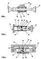
- This valve 40 adapts especially in the damping devices known in prior art as shown schematically on Figure 1.
- the wall 33 forms the movable piston inside the cylinder 30 and said piston 33 is connected via a rod 60, which crosses the two bottoms of cylinder 30, at the second element of structure 20, while the cylinder 30 is fixed on the first structural element 10.
- the valve 40 (not shown) is in this case placed in the movable piston 33.
- the efficiency of the known damping device is therefore greatly increased thanks to the invention but the device however still has some disadvantages. So as mentioned earlier, the displacements of the piston 33 result from the forces of compression and traction of the rod 60. These forces can be very significant, the risk of buckling of the rod exists.
- At least one of said pistons 37 and 38 is integral with the second structural element 20.
- the piston 38 is connected mechanically to this second structural element 20, then that the other movable piston 37 is integral with said first piston 38 by means of a rod 60 which passes through said partition wall 33 of chambers. 31 and 32.
- the piston 38 of Figure 2 can be formed by a tube which is provided at its end opposite to chamber 32 of means, generally slightly articulated, for fixing to said second structural element 20.
- This second structural element 20 can for example be the deck of a bridge.
- the main advantage of this implementation is that the rod 60 of the device is only stressed in tension, eliminating in this case practically any danger of buckling of this rod, so that it can have a minimum dimension. This solution is particularly suitable when it is necessary to cushion the effects of the earthquake in the sense axial, ie when the structural elements 10, 20 which are to be linked, are opposite one of the other in the direction of their movement.
- each of the two movable pistons 37 and 38 can be formed in the form a tube which, on the side of its respective chamber 31 or 32, moves with sealing in the cylinder 30, fixed on the bridge stack 10.
- the other end of the pistons 37 and 38 is provided for example with stops, or any articulated means, or not, which allow them to be linked mechanically to the second structural element 20.
- the pistons 37 and 38 in this case are not connected to each other the other.
- the partition wall 33 obviously incorporates passage 34, valve 40 and possibly the small port 39 and the shock absorber works similar to that described above.
- the device is very compact because the useful cross section of the piston is maximum, due to the absence of the stem.
- the rod being replaced by tubular pistons having a moment much larger inertia, their buckling is a lot less critical and it is generally not necessary to take it into account.
- the invention provides for provide a reservoir 70 in at least one of the pistons mobile.
- This reservoir 70 is connected to at least one of said rooms 31, 32 by a small duct 71 advantageously fitted with a valve (not shown) which instantly isolates the reservoir 70 of the chamber to which it is connected when the pressure in the latter increases beyond of a value fixed in advance.
- This tank 70 is partially or completely filled with a material compressible 72 adapted to compress to allow expansion of said fluid product.
- This compressible material 72 can for example be a plastic foam, for example an elastomer, compatible with the product fluid used in the device. This foam contains closed air cells and is therefore very compressible. It is therefore this reservoir 70 which plays the role expansion tank very efficiently and which avoids any hydraulic circuit external to the device.
- the reservoir 70 When the device is assembled, the reservoir 70 is filled of fluid just like chambers 31 and 32.
- the only air contained in the reservoir is that of the cells of the foam 72.
- the device In normal service the device is not subjected to no significant internal pressure.
- the fluid temperature increases, it expands and thanks to orifices which connect the chamber (s) 31 and 32 to the reservoir 70 of the piston, the fluid, which is globally confined, sees its pressure increase and, consequently, compresses the air in the foam cells.
- the expansion of the fluid is very slow, we can consider that it is done at constant temperature.
- the increase in fluid volume is thus of the same order larger than the compression of the air in the cells.
- a another advantage of this embodiment is that it does has neither vent nor purge, and therefore allows installation and operation of the device in any position.
- the valve (not shown) of which is provided with the communication conduit 71 between one of the chambers 31, 32 and the reservoir 70 containing the foam, protects it as well as the foam against all possible deterioration when the device operates during a earthquake, in which case the chamber pressure may reach several hundred bars.
- the embodiment of the invention which combines with maximum all of the above benefits therefore consists of an oleodynamic damping device produced according to one of the embodiments of FIGS. 2 and 3, comprising a valve according to the invention and incorporating a expansion tank according to figure 5.
- the embodiment of the device shown in the Figure 4 which shows the valve in more detail 40, relates more particularly to the mode of embodiment of the invention shown in FIG. 3, since the wall 33 is not crossed by a rod. he must be clear that this valve also fits all the other embodiments of the invention described previously.
Claims (14)
- Baugruppe, aufweisend eine erstes und ein zweites Baustrukturelement (10, 20) und ein Dämpfungselement zwischen diesen beiden Elementen, wobei das Dämpfungselement dazu ausgelegt ist, zumindest Relativverschiebungen zwischen den ersten und zweiten Strukturelementen (10, 20) bei schnellen Bewegungen aufzunehmen, wobei die Vorrichtung einen in bezug auf das erste Strukturelement (10) feststehenden Zylinder (30) aufweist, der zwei Kammern (31, 32) festlegt, die ein Produktfluid einschließen und durch eine Wand (33) getrennt sind, wobei zumindest ein beweglicher Kolben (33; 37, 38) in der Kammer (30) gleitverschiebbar ist, wobei die Wand (33) zumindest einen Durchlass (34) aufweist, der die beiden Kammern (31, 32) miteinander verbindet, wobei die Vorrichtung zumindest ein Ventil aufweist, welches in seiner Ruhestellung den Durchlass (34) verschließt, und das bei einer Erhöhung des Drucks in den Kammern (31, 32) aufgrund einer schnellen Bewegung des zweiten Strukturelements (20) in bezug auf das erste Strukturelement (10) den Durchlass (34) öffnet und dadurch Fluid unter hohem Druck von einer Kammer in die andere Kammer strömen lässt, wobei das Ventil (40) in Richtung auf seine Schließstellung durch ein elastisches Organ (45) vorgespannt ist, dadurch gekennzeichnet, dass das Ventil (40) bidirektionell ist und einen Ventilkolben (41) aufweist, der in einem Kanal (42) im wesentlichen senkrecht zu dem Durchlass (34) zwischen einer Schließstellung, in welcher er den Durchlass (34) dicht verschließt und einer Öffnungsstellung gleitbeweglich ist, in welcher er den Durchlass (34) öffnet.
- Baugruppe nach Anspruch 1, in welchem der Kolben (41) in Richtung auf seine Schließstellung durch eine regelbare Druckfeder (35) vorgespannt ist.
- Baugruppe nach Anspruch 2, wobei der Ventilkolben (41), im wesentlichen zylindrisch ist und an seinem Ende, welches den Durchlass (34) in der Schließstellung versperrt, zumindest eine Vertiefung (50) aufweist, die zu dem Durchlass (34) derart ausmündet, dass bei einer Druckerhöhung in den Kammern (31, 32) der Ventilkolben (41) den Durchlass (34) gegen den Druck der Feder (45) durch die axiale Kraftkomponente öffnet, die in zumindest einer Eintiefung (50) zur Ausbildung gelangt.
- Baugruppe nach Anspruch 2 oder 3, wobei die Feder (45) einerseits auf den Ventilkolben (41) einwirkt und andererseits mit einem ersten Anschlagorgan (43) in fester Verbindung steht, dessen Position in dem Kanal (42) als Funktion des gewünschten Drucks der Feder (45) festgelegt sein kann.
- Baugruppe nach einem der Ansprüche 1 bis 4, wobei der Kanal (42) ein zweites Anschlagorgan (43b) umfasst, dessen Position regelbar ist und das in dem Durchlass (34) endet, wobei der Ventilkolben (41) mit dem zweiten Anschlagorgan (43b) in seiner Schließstellung zusammenwirkt, wobei das Vorliegen des zweiten Anschlagorgans (43b) in dem Durchlass (34) einen verringerten Durchmesserteil bildet, der das Dämpfungsverhalten durch einen Druckverlust der Vorrichtung festlegt.
- Baugruppe nach Anspruch 5, wobei der Durchlass (34) zumindest einen Teil verringerten Durchmessers aufweist, der das Dämpfungsverhalten durch Druckverlust der Vorrichtung festlegt.
- Baugruppe nach einem der vorangehenden Ansprüche, wobei die Trennwand (33) der beiden Kammern (31, 32) außerdem eine Öffnung (39) aufweist, welche die beiden Kammern (31, 32) untereinander derart verbindet, dass eine Relativverschiebung zwischen den Strukturelementen (10, 20) bei langsamen Bewegungen möglich ist.
- Baugruppe nach einem der vorangehenden Ansprüche, wobei die die beiden Kammern (31, 32) trennende Wand (33) in bezug auf den feststehenden Zylinder (30) beweglich ist und einen beweglichen Kolben im Innern des Zylinders bildet, wobei der bewegliche Kolben (33) mit dem zweiten Strukturelement (20) durch eine Stange (60) fest verbunden ist.
- Baugruppe nach einem der Ansprüche 1 bis 7, wobei die in beiden Kammern (31, 32) trennende Wand in bezug auf den Zylinder (30) feststeht, und wobei jede Kammer (31, 32) auf der Seite in Gegenüberlage zu der Wand durch einen beweglichen Kolben (37, 38) begrenzt ist, wobei zumindest einer der beweglichen Kolben (37, 38) mit dem zweiten Strukturelement (20) fest verbunden ist.
- Baugruppe nach Anspruch 9, wobei der erste Kolben (38) der beiden beweglichen Kolben (37, 38) mit dem zweiten Strukturelement (20) fest verbunden ist, und wobei der andere bewegliche Kolben (37) mit dem ersten Kolben (38) durch eine Stange (60) fest verbunden ist, welche die Trennwand (33) der Kammern (31, 32) durchsetzt.
- Baugruppe nach Anspruch 9, wobei die beiden beweglichen Kolben (37, 38) mit dem zweiten Strukturelement (20) fest und miteinander nicht verbunden sind.
- Baugruppe nach einem der vorangehenden Ansprüche, wobei zumindest ein beweglicher Kolben (33; 37, 38) einen Vorratsbehälter (70) umfasst, der zumindest mit einer der Kammern (31, 32) durch einen kleinen Kanal (71) verbunden ist, wobei der Vorratsbehälter (70) zumindest teilweise mit einem kompressiblen Material (72) gefüllt ist, das dazu ausgelegt ist, zu komprimieren, um eine Verdünnung des Produktfluids zu ermöglichen.
- Baugruppe nach Anspruch 12, wobei das kompressible Material (32) ein Kunststoffschaum ist, der mit dem Produktfluid kompatibel ist.
- Baugruppe nach einem der vorangehenden Ansprüche, wobei die Baustruktur eine Brücke ist, und wobei die ersten und zweiten Strukturelemente (10, 20) ein Widerlager, eine Säule oder ein Brückenüberbau sein können.
Applications Claiming Priority (3)
| Application Number | Priority Date | Filing Date | Title |
|---|---|---|---|
| FR9600162 | 1996-01-09 | ||
| FR9600162A FR2743383B1 (fr) | 1996-01-09 | 1996-01-09 | Dispositif d'amortissement pour des elements d'une structure de genie civil |
| PCT/FR1997/000032 WO1997025497A1 (fr) | 1996-01-09 | 1997-01-08 | Dispositif d'amortissement pour des elements d'une structure de genie civil |
Publications (2)
| Publication Number | Publication Date |
|---|---|
| EP0873457A1 EP0873457A1 (de) | 1998-10-28 |
| EP0873457B1 true EP0873457B1 (de) | 2003-04-09 |
Family
ID=9487970
Family Applications (1)
| Application Number | Title | Priority Date | Filing Date |
|---|---|---|---|
| EP97900249A Expired - Lifetime EP0873457B1 (de) | 1996-01-09 | 1997-01-08 | Dämpfungsvorrichtung für hoch- und tiefbauelemente |
Country Status (11)
| Country | Link |
|---|---|
| US (1) | US6108987A (de) |
| EP (1) | EP0873457B1 (de) |
| JP (1) | JP3928117B2 (de) |
| KR (1) | KR100528679B1 (de) |
| AU (1) | AU1383697A (de) |
| DE (1) | DE69720683T2 (de) |
| ES (1) | ES2196296T3 (de) |
| FR (1) | FR2743383B1 (de) |
| PT (1) | PT873457E (de) |
| TR (1) | TR199801334T2 (de) |
| WO (1) | WO1997025497A1 (de) |
Families Citing this family (19)
| Publication number | Priority date | Publication date | Assignee | Title |
|---|---|---|---|---|
| FR2804709B1 (fr) * | 2000-02-09 | 2002-04-19 | Campenon Bernard Sge | Dispositif permettant de limiter le deplacement relatif de deux elements d'une structure de genie civil et structure comprenant un tel dispositif |
| US20040028686A1 (en) * | 2001-06-28 | 2004-02-12 | Faulk Ward Page | Targeted delivery of cytotoxic drugs a) to activated lymphocytes in patients with transplated organs, b) as radiosensitizers to cancer cells in patients undergoing radiation therapy, and c) in vitamin-binding proteins as drug carriers in the diagnosis and treatment of cancer |
| KR100476439B1 (ko) * | 2002-03-12 | 2005-03-16 | 박대원 | 건축 구조물용 내진장치 |
| US8001734B2 (en) | 2004-05-18 | 2011-08-23 | Simpson Strong-Tie Co., Inc. | Moment frame links wall |
| US7603725B2 (en) * | 2004-06-07 | 2009-10-20 | Kerry Sheldon Harris | Shock balance controller |
| KR100708781B1 (ko) * | 2005-08-09 | 2007-04-18 | 주식회사 로텍인스트루먼트 | 토목 구조물 및 지중 변위 측정장치 |
| KR100722850B1 (ko) * | 2006-04-19 | 2007-05-30 | 주식회사 포스코건설 | 지진에 의한 교량의 붕괴방지 및 충격흡수를 위한 교량용낙교방지장치 |
| US20080265478A1 (en) * | 2007-02-05 | 2008-10-30 | Tyn Smith | Wind turbine systems dampers |
| KR100927737B1 (ko) * | 2007-11-29 | 2009-11-18 | 한국건설기술연구원 | 건축 구조물의 내진보강 복합장치 및 내진 보강구조 |
| US20090194921A1 (en) * | 2008-02-05 | 2009-08-06 | Tyn Smith | High force civil engineering damper |
| JP6099882B2 (ja) * | 2011-05-18 | 2017-03-22 | 中部電力株式会社 | ダムの水門柱の耐震性向上工法 |
| CN102901660B (zh) * | 2012-10-16 | 2014-08-13 | 绍兴文理学院 | 一种旋杆式三轴试样制样器及其制样方法 |
| CN105507439B (zh) * | 2015-11-24 | 2018-07-31 | 北京工业大学 | 一种活塞式填充压簧自复位耗能支撑 |
| CN109057090B (zh) * | 2018-08-19 | 2023-11-03 | 郑州大学 | 一种具有自复位和耗能功能的钢筋混凝土摇摆剪力墙 |
| EP3760893A1 (de) | 2019-07-03 | 2021-01-06 | Soletanche Freyssinet | System zur überwachung einer dämpfungsvorrichtung |
| CN111519768A (zh) * | 2020-04-29 | 2020-08-11 | 中国一冶集团有限公司 | 一种装配式建筑减震结构 |
| CN111852054B (zh) * | 2020-08-06 | 2022-01-11 | 南昌大学 | 一种砌体墙抗震加强装置 |
| CN112211087B (zh) * | 2020-08-25 | 2021-11-30 | 河海大学 | 可更换套接联排四向限位阻尼卡榫及其安装方法 |
| CN114960396A (zh) * | 2022-04-26 | 2022-08-30 | 中铁第四勘察设计院集团有限公司 | 一种斜拉桥弹性与锁定限位约束结构体系 |
Family Cites Families (9)
| Publication number | Priority date | Publication date | Assignee | Title |
|---|---|---|---|---|
| US2090751A (en) * | 1934-06-30 | 1937-08-24 | Francisco Liebhold | Hydraulic shock absorber |
| US2309499A (en) * | 1941-03-22 | 1943-01-26 | Gulf Research Development Co | Shock absorbing apparatus |
| GB719666A (en) * | 1952-06-25 | 1954-12-08 | Westinghouse Brake & Signal | Improvements relating to liquid filled dash pot devices |
| DE1580552A1 (de) * | 1966-08-17 | 1970-10-29 | Porsche Kg | Hydraulischer Teleskopschwingungsdaempfer fuer Fahrzeuge,insbesondere Kraftfahrzeuge |
| GB1362409A (en) * | 1972-11-20 | 1974-08-07 | Martonair Ltd | Dashpot |
| FR2544432B1 (fr) * | 1982-11-09 | 1985-11-29 | Dragages Travaux Publics | Verin parasismique pour structure elastiquement appuyee |
| JP2602440B2 (ja) * | 1988-01-06 | 1997-04-23 | 株式会社竹中工務店 | 上下方向免震装置 |
| US5347771A (en) * | 1991-06-20 | 1994-09-20 | Kajima Corporation | High damping device for seismic response controlled structure |
| US5462141A (en) * | 1993-05-07 | 1995-10-31 | Tayco Developments, Inc. | Seismic isolator and method for strengthening structures against damage from seismic forces |
-
1996
- 1996-01-09 FR FR9600162A patent/FR2743383B1/fr not_active Expired - Fee Related
-
1997
- 1997-01-08 TR TR1998/01334T patent/TR199801334T2/xx unknown
- 1997-01-08 KR KR1019980705187A patent/KR100528679B1/ko not_active IP Right Cessation
- 1997-01-08 EP EP97900249A patent/EP0873457B1/de not_active Expired - Lifetime
- 1997-01-08 JP JP52491997A patent/JP3928117B2/ja not_active Expired - Lifetime
- 1997-01-08 WO PCT/FR1997/000032 patent/WO1997025497A1/fr active IP Right Grant
- 1997-01-08 DE DE69720683T patent/DE69720683T2/de not_active Expired - Fee Related
- 1997-01-08 PT PT97900249T patent/PT873457E/pt unknown
- 1997-01-08 US US09/101,160 patent/US6108987A/en not_active Expired - Lifetime
- 1997-01-08 AU AU13836/97A patent/AU1383697A/en not_active Abandoned
- 1997-01-08 ES ES97900249T patent/ES2196296T3/es not_active Expired - Lifetime
Also Published As
| Publication number | Publication date |
|---|---|
| ES2196296T3 (es) | 2003-12-16 |
| JPH11510233A (ja) | 1999-09-07 |
| PT873457E (pt) | 2003-08-29 |
| EP0873457A1 (de) | 1998-10-28 |
| JP3928117B2 (ja) | 2007-06-13 |
| DE69720683T2 (de) | 2004-01-22 |
| FR2743383A1 (fr) | 1997-07-11 |
| DE69720683D1 (de) | 2003-05-15 |
| KR19990077054A (ko) | 1999-10-25 |
| WO1997025497A1 (fr) | 1997-07-17 |
| AU1383697A (en) | 1997-08-01 |
| US6108987A (en) | 2000-08-29 |
| KR100528679B1 (ko) | 2006-01-27 |
| TR199801334T2 (xx) | 1998-10-21 |
| FR2743383B1 (fr) | 1999-03-05 |
Similar Documents
| Publication | Publication Date | Title |
|---|---|---|
| EP0873457B1 (de) | Dämpfungsvorrichtung für hoch- und tiefbauelemente | |
| EP0750724B1 (de) | Regel- und modulierbare hydropneumatische dämpfungsvorrichtung | |
| FR2609128A1 (fr) | Amortisseur a compensation de charge | |
| EP1250539A1 (de) | Dämpfer mit hoch ableitungs leistung | |
| CA2762767C (fr) | Amortisseur et atterrisseur equipe d'un tel amortisseur | |
| FR2845440A1 (fr) | Dispositif de commande de valves | |
| EP0335786A1 (de) | Elastischer Streben mit integriertem, hydro-mechanischem Resonator, insbesondere für die Aufhängung eines Getriebes an einen Drehflügler und eine Aufhängevorrichtung mit einer solchen Verwendungsmöglichkeit | |
| EP0873458B1 (de) | Einheit bestehend aus zwei elemente einer hoch- oder tiefbaustruktur und einer verbindungsvorrichtung | |
| EP0060181B1 (de) | Vorgespannter hydropneumatischer Druckspeicher mit Überdrucksicherung | |
| CA2260834A1 (fr) | Dispositif pour amortir les vibrations d'un cable | |
| WO2000049358A1 (fr) | Dispositif anti-recul avec frein, compensateur du frein et recuperateur | |
| FR2964434A1 (fr) | Amortisseur a haut pouvoir dissipatif et pratiquement sans huile | |
| FR2528382A1 (fr) | Amortisseur de vibrations et notamment adaptateur de frequence pour pale d'helicoptere | |
| EP0198733B1 (de) | Hydroelastische Aufhängevorrichtung für selbsthebende mobile Bohrplattformen | |
| FR3089838A1 (fr) | Appareil hydraulique à percussions équipé d’un dispositif d’étanchéité | |
| EP0296087A1 (de) | Doppelt wirkender Stossdämpfer, der die Drosselung einer Flüssigkeit beim Durchströmen einer Verengung hervorruft | |
| FR2914716A1 (fr) | Butee de compression hydraulique, notamment pour amortisseur hydraulique de suspension de vehicule automobile | |
| EP1554506A2 (de) | Hydraulischer anschlagpuffer für kraftfahrzeugstossdämpfer, stossdämpfendes system und verfahren zum betrieb eines solchen systems | |
| FR2935033A1 (fr) | Dispositif de compensation du volume du corps d'un amortisseur hydraulique de suspension | |
| EP0013227B1 (de) | Hydraulische Dämpfungsvorrichtung für durch Stösse und Schwingungen hervorgerufene Belastung | |
| FR2552514A1 (fr) | Amortisseur du type fluidique | |
| EP0866924A1 (de) | Teleskopdämpfer mit einem laminatkanal | |
| FR2821654A1 (fr) | Amortisseur ou limiteur d'efforts en particulier pour ouvrages de genie civil | |
| BE629690A (de) | ||
| FR3066001A1 (fr) | Dispositif hydroelastique comportant un systeme de blocage |
Legal Events
| Date | Code | Title | Description |
|---|---|---|---|
| PUAI | Public reference made under article 153(3) epc to a published international application that has entered the european phase |
Free format text: ORIGINAL CODE: 0009012 |
|
| 17P | Request for examination filed |
Effective date: 19980805 |
|
| AK | Designated contracting states |
Kind code of ref document: A1 Designated state(s): DE ES FR GB GR IT PT |
|
| 17Q | First examination report despatched |
Effective date: 20020320 |
|
| GRAH | Despatch of communication of intention to grant a patent |
Free format text: ORIGINAL CODE: EPIDOS IGRA |
|
| GRAH | Despatch of communication of intention to grant a patent |
Free format text: ORIGINAL CODE: EPIDOS IGRA |
|
| GRAA | (expected) grant |
Free format text: ORIGINAL CODE: 0009210 |
|
| AK | Designated contracting states |
Designated state(s): DE ES FR GB GR IT PT |
|
| REG | Reference to a national code |
Ref country code: GB Ref legal event code: FG4D Free format text: NOT ENGLISH |
|
| GBT | Gb: translation of ep patent filed (gb section 77(6)(a)/1977) | ||
| REG | Reference to a national code |
Ref country code: GR Ref legal event code: EP Ref document number: 20030402401 Country of ref document: GR |
|
| REG | Reference to a national code |
Ref country code: ES Ref legal event code: FG2A Ref document number: 2196296 Country of ref document: ES Kind code of ref document: T3 |
|
| PLBE | No opposition filed within time limit |
Free format text: ORIGINAL CODE: 0009261 |
|
| STAA | Information on the status of an ep patent application or granted ep patent |
Free format text: STATUS: NO OPPOSITION FILED WITHIN TIME LIMIT |
|
| 26N | No opposition filed |
Effective date: 20040112 |
|
| PG25 | Lapsed in a contracting state [announced via postgrant information from national office to epo] |
Ref country code: DE Free format text: LAPSE BECAUSE OF NON-PAYMENT OF DUE FEES Effective date: 20040803 |
|
| PG25 | Lapsed in a contracting state [announced via postgrant information from national office to epo] |
Ref country code: GR Free format text: LAPSE BECAUSE OF NON-PAYMENT OF DUE FEES Effective date: 20040804 |
|
| PG25 | Lapsed in a contracting state [announced via postgrant information from national office to epo] |
Ref country code: IT Free format text: LAPSE BECAUSE OF NON-PAYMENT OF DUE FEES;WARNING: LAPSES OF ITALIAN PATENTS WITH EFFECTIVE DATE BEFORE 2007 MAY HAVE OCCURRED AT ANY TIME BEFORE 2007. THE CORRECT EFFECTIVE DATE MAY BE DIFFERENT FROM THE ONE RECORDED. Effective date: 20050108 |
|
| PGFP | Annual fee paid to national office [announced via postgrant information from national office to epo] |
Ref country code: GB Payment date: 20101230 Year of fee payment: 15 |
|
| PGFP | Annual fee paid to national office [announced via postgrant information from national office to epo] |
Ref country code: FR Payment date: 20120216 Year of fee payment: 16 |
|
| PGFP | Annual fee paid to national office [announced via postgrant information from national office to epo] |
Ref country code: PT Payment date: 20120103 Year of fee payment: 16 |
|
| PGFP | Annual fee paid to national office [announced via postgrant information from national office to epo] |
Ref country code: ES Payment date: 20120105 Year of fee payment: 16 |
|
| REG | Reference to a national code |
Ref country code: PT Ref legal event code: MM4A Free format text: LAPSE DUE TO NON-PAYMENT OF FEES Effective date: 20130708 |
|
| GBPC | Gb: european patent ceased through non-payment of renewal fee |
Effective date: 20130108 |
|
| REG | Reference to a national code |
Ref country code: FR Ref legal event code: ST Effective date: 20130930 |
|
| PG25 | Lapsed in a contracting state [announced via postgrant information from national office to epo] |
Ref country code: PT Free format text: LAPSE BECAUSE OF NON-PAYMENT OF DUE FEES Effective date: 20130708 |
|
| PG25 | Lapsed in a contracting state [announced via postgrant information from national office to epo] |
Ref country code: FR Free format text: LAPSE BECAUSE OF NON-PAYMENT OF DUE FEES Effective date: 20130131 Ref country code: GB Free format text: LAPSE BECAUSE OF NON-PAYMENT OF DUE FEES Effective date: 20130108 |
|
| REG | Reference to a national code |
Ref country code: ES Ref legal event code: FD2A Effective date: 20140324 |
|
| PG25 | Lapsed in a contracting state [announced via postgrant information from national office to epo] |
Ref country code: ES Free format text: LAPSE BECAUSE OF NON-PAYMENT OF DUE FEES Effective date: 20130109 |