EP0872610A2 - Roof window - Google Patents
Roof window Download PDFInfo
- Publication number
- EP0872610A2 EP0872610A2 EP98104386A EP98104386A EP0872610A2 EP 0872610 A2 EP0872610 A2 EP 0872610A2 EP 98104386 A EP98104386 A EP 98104386A EP 98104386 A EP98104386 A EP 98104386A EP 0872610 A2 EP0872610 A2 EP 0872610A2
- Authority
- EP
- European Patent Office
- Prior art keywords
- spring
- skylight according
- additional
- frame
- piston rod
- Prior art date
- Legal status (The legal status is an assumption and is not a legal conclusion. Google has not performed a legal analysis and makes no representation as to the accuracy of the status listed.)
- Granted
Links
Images


Classifications
-
- E—FIXED CONSTRUCTIONS
- E04—BUILDING
- E04D—ROOF COVERINGS; SKY-LIGHTS; GUTTERS; ROOF-WORKING TOOLS
- E04D13/00—Special arrangements or devices in connection with roof coverings; Protection against birds; Roof drainage; Sky-lights
- E04D13/03—Sky-lights; Domes; Ventilating sky-lights
- E04D13/035—Sky-lights; Domes; Ventilating sky-lights characterised by having movable parts
- E04D13/0357—Sky-lights; Domes; Ventilating sky-lights characterised by having movable parts the parts pivoting about an axis supported on a hinged frame or arms
-
- E—FIXED CONSTRUCTIONS
- E05—LOCKS; KEYS; WINDOW OR DOOR FITTINGS; SAFES
- E05F—DEVICES FOR MOVING WINGS INTO OPEN OR CLOSED POSITION; CHECKS FOR WINGS; WING FITTINGS NOT OTHERWISE PROVIDED FOR, CONCERNED WITH THE FUNCTIONING OF THE WING
- E05F1/00—Closers or openers for wings, not otherwise provided for in this subclass
- E05F1/08—Closers or openers for wings, not otherwise provided for in this subclass spring-actuated, e.g. for horizontally sliding wings
- E05F1/10—Closers or openers for wings, not otherwise provided for in this subclass spring-actuated, e.g. for horizontally sliding wings for swinging wings, e.g. counterbalance
- E05F1/1091—Closers or openers for wings, not otherwise provided for in this subclass spring-actuated, e.g. for horizontally sliding wings for swinging wings, e.g. counterbalance with a gas spring
-
- E—FIXED CONSTRUCTIONS
- E05—LOCKS; KEYS; WINDOW OR DOOR FITTINGS; SAFES
- E05Y—INDEXING SCHEME RELATING TO HINGES OR OTHER SUSPENSION DEVICES FOR DOORS, WINDOWS OR WINGS AND DEVICES FOR MOVING WINGS INTO OPEN OR CLOSED POSITION, CHECKS FOR WINGS AND WING FITTINGS NOT OTHERWISE PROVIDED FOR, CONCERNED WITH THE FUNCTIONING OF THE WING
- E05Y2201/00—Constructional elements; Accessories therefore
- E05Y2201/40—Motors; Magnets; Springs; Weights; Accessories therefore
- E05Y2201/404—Motors; Magnets; Springs; Weights; Accessories therefore characterised by the function
- E05Y2201/416—Motors; Magnets; Springs; Weights; Accessories therefore characterised by the function for counterbalancing
-
- E—FIXED CONSTRUCTIONS
- E05—LOCKS; KEYS; WINDOW OR DOOR FITTINGS; SAFES
- E05Y—INDEXING SCHEME RELATING TO HINGES OR OTHER SUSPENSION DEVICES FOR DOORS, WINDOWS OR WINGS AND DEVICES FOR MOVING WINGS INTO OPEN OR CLOSED POSITION, CHECKS FOR WINGS AND WING FITTINGS NOT OTHERWISE PROVIDED FOR, CONCERNED WITH THE FUNCTIONING OF THE WING
- E05Y2201/00—Constructional elements; Accessories therefore
- E05Y2201/40—Motors; Magnets; Springs; Weights; Accessories therefore
- E05Y2201/404—Motors; Magnets; Springs; Weights; Accessories therefore characterised by the function
- E05Y2201/422—Motors; Magnets; Springs; Weights; Accessories therefore characterised by the function for opening
- E05Y2201/426—Motors; Magnets; Springs; Weights; Accessories therefore characterised by the function for opening for the initial opening movement
-
- E—FIXED CONSTRUCTIONS
- E05—LOCKS; KEYS; WINDOW OR DOOR FITTINGS; SAFES
- E05Y—INDEXING SCHEME RELATING TO HINGES OR OTHER SUSPENSION DEVICES FOR DOORS, WINDOWS OR WINGS AND DEVICES FOR MOVING WINGS INTO OPEN OR CLOSED POSITION, CHECKS FOR WINGS AND WING FITTINGS NOT OTHERWISE PROVIDED FOR, CONCERNED WITH THE FUNCTIONING OF THE WING
- E05Y2900/00—Application of doors, windows, wings or fittings thereof
- E05Y2900/10—Application of doors, windows, wings or fittings thereof for buildings or parts thereof
- E05Y2900/13—Application of doors, windows, wings or fittings thereof for buildings or parts thereof characterised by the type of wing
- E05Y2900/148—Windows
- E05Y2900/152—Roof windows
Landscapes
- Engineering & Computer Science (AREA)
- Architecture (AREA)
- Civil Engineering (AREA)
- Structural Engineering (AREA)
- Closing And Opening Devices For Wings, And Checks For Wings (AREA)
- Glass Compositions (AREA)
- Liquid Crystal (AREA)
- Devices For Conveying Motion By Means Of Endless Flexible Members (AREA)
- Window Of Vehicle (AREA)
- Optical Head (AREA)
- Magnetic Heads (AREA)
- Wing Frames And Configurations (AREA)
Abstract
Description
Die Erfindung betrifft ein Dachfenster, insbesondere Schwingflügel-Dachfenster, mit einem Blendrahmen und einem Flügelrahmen, der mittels gelenkig an ihm angeordneten Hilfsrahmenprofilen um eine Schwingachse schwenkbeweglich gelagert ist, wobei sich die Schwingachse horizontal und etwa im mittleren Bereich am Fensterflügel befindet, und mit einer eine Schwinghilfe bildenden Federvorrichtung.The invention relates to a roof window, in particular Swing-wing skylight, with a frame and a wing frame that is articulated to subframe profiles arranged by one Swing axis is pivotally mounted, wherein the oscillation axis is horizontal and approximately in the middle Area located on the casement, and with a spring device forming a vibration aid.
Aus dem deutschen Gebrauchsmuster 74 16 262 ist bekannt, bei einem Schwingflügel-Dachfenster eine Federvorrichtung vorzusehen, die zwei Schwenkarme aufweist, welche mit ihrem einen Ende schwenkbar am Blendrahmen befestigt sind und deren andere Enden an Hilfsrahmenprofilen angreifen, die einerseits schwenkbeweglich am Blendrahmen und andererseits schwenkbeweglich am Flügelrahmen gelagert sind. Die Federvorrichtung übt beim Entriegeln des Fensters eine Aufstellkraft auf das jeweilige Hilfsrahmenprofil aus, so daß dies ohne große Kraftanstrengung um die Schwingachse am Blendrahmen verschwenkt werden kann und somit das Verbringen des Flügelrahmens in eine Schwingöffnungsstellung unterstützt. Bei dieser Schwingöffnungsstellung handelt es sich nicht nur um eine Belüftungsstellung, sondern sie läßt auch auf einfache Weise eine Auflenglasreinigung zu, da der Flügelrahmen derart weit um die Schwingachse verschwenkt werden kann, daß die Außenglasfläche dem Rauminneren zugewandt ist.From German utility model 74 16 262 it is known a spring device for a swing-wing roof window to provide the two swivel arms has which with one end pivotable on Frame are attached and their other ends attack subframe profiles that on the one hand swiveling on the frame and on the other are pivotally mounted on the casement. The Spring device exercises when unlocking the window a positioning force on the respective subframe profile out, so this without much effort be pivoted about the swing axis on the frame can and thus the placement of the casement supported in a swing opening position. At this swing opening position is not just a ventilation position, but it also allows a cleaning of the lens too, because the sash is so far around the Swing axis can be pivoted that the Exterior glass surface facing the interior of the room.
Ferner sind Dachfenster bekannt, die als Klappfenster ausgebildet sind, das heißt, der Fensterflügel ist im Bereich des oberen Blendrahmen-Querprofils schwenkbar gelagert. Eine Schwingachse ist nicht vorhanden.Furthermore, roof windows are known, which are known as hinged windows are trained, that is, the window sash is in the area of the upper frame cross section pivoted. A swing axis is not available.
Klappschwingfenster weisen sowohl eine Schwingachse als auch eine Klappachse auf, das heißt, sie ermöglichen sowohl eine Schwingöffnungsstellung als auch eine Klappöffnungsstellung. Die vorliegende Erfindung ist sowohl bei Schwingflügel-Dachfenstern als auch bei Klappschwingflügel-Dachfenstern realisierbar.Hinged swing windows have both a swing axis as well as a folding axis, that is, they enable both a swing opening position as well a folding opening position. The present invention is both for swing-wing skylights and also feasible with swing-wing roof windows.
Bei dem bekannten Schwingflügel-Dachfenster des deutschen Gebrauchsmusters 74 16 262 besteht der Nachteil, daß im Anfangsöffnungsbereich die Federvorrichtung nur eine relativ kleine Kraftkomponente für die Öffnungsbewegung aufbringen kann, da die Wirklinie der Federvorrichtung einen spitzen Winkel mit der Längserstreckung des jeweiligen Hilfsrahmenprofils einschließt. Wird zur Lösung dieses Problems eine Federvorrichtung mit stärkerer Federkraft eingesetzt, so wird zwar die Anfangsöffnungsbewegung besser unterstützt, jedoch im Zuge der weiteren Öffnungsbewegung eine zu große Öffnungskraft auf den Fensterflügel ausgeübt, so daß sich dieser unkontrolliert weit öffnet. In the known swing wing skylight German utility model 74 16 262 is the Disadvantage that the spring device in the opening area only a relatively small force component for the opening movement because the Line of action of the spring device an acute angle with the longitudinal extent of the respective subframe profile includes. Will solve this problem a spring device with stronger spring force used, the initial opening movement is indeed better supported, however in the course of further opening movement a too large opening force exerted on the window sash so that this opens uncontrollably.
Der Erfindung liegt daher die Aufgabe zugrunde, ein Dachfenster der eingangs genannten Art anzugeben, das über seinen Schwingöffnungsbereich eine verbesserte Öffnungsbewegungs-Unterstützung aufweist.The invention is therefore based on the object To specify roof windows of the type mentioned at the outset, that improved over its swing opening area Has opening movement support.
Diese Aufgabe wird erfindungsgemäß dadurch gelöst, daß die Federvorrichtung teleskopartig ausgebildet ist und mit einem Ende am Flügelrahmen schwenkbeweglich befestigt ist und mit einem anderen Ende mit dem Blendrahmen zusammenwirkt, daß die Federvorrichtung mindestens eine Hauptfeder und mindestens eine Zusatzfeder aufweist, wobei die Hauptfeder über den gesamten Stellweg der Federvorrichtung und die die Stellkraft der Hauptfeder unterstützende Zusatzfeder nur über einen Abschnitt des Stellwegs wirkt. Durch den Einsatz mindestens zweier Federn, von denen die eine über den gesamten Stellweg und die andere nur über einen Abschnitt des Stellwegs wirkt, wird die Schwingöffnungsbewegung -je nach Drehwinkelstellung- unterschiedlich stark unterstützt. Die Anordnung ist vorzugsweise derart getroffen, daß beide Federn, deren Kräfte sich addieren, während der Anfangsöffnungsbewegung wirksam sind. Ist eine bestimmte Öffnungsstellung erreicht, so endet die Unterstützung der Zusatzfeder, so daß nur noch die Hauptfeder über den weiteren Stellweg wirksam ist. Im Bereich, in dem nur die Hauptfeder wirkt, hat der Fensterflügel bereits eine Drehposition eingenommen, in der -aufgrund des Verschwenkens der Federvorrichtung- eine entsprechend vergrößerte Kraftkomponente für die Öffnungsbewegung zur Verfügung gestellt wird. Aufgrund der Erfindung ist es daher mit sehr einfachen Mitteln möglich, das Wohndachfenster gegen die Schwerkraft in der jeweils gewünschten Öffnungsposition zu halten.According to the invention, this object is achieved by that the spring device is telescopic is pivotable and with one end on the casement is attached and with another end cooperates with the frame that the spring device at least one main spring and at least has an additional spring, the main spring over the entire travel of the spring device and the main spring supporting force Additional spring only over a section of the Travel affects. By using at least two feathers, one over the entire Travel and the other only over a section of the travel path, the swing opening movement -Different depending on the angle of rotation strongly supported. The arrangement is preferred hit so that both springs, their forces add up during the initial opening movement are effective. Is a certain opening position reached, the support of the additional spring ends, so that only the main spring over the other Travel is effective. In the area where only the main spring works, the window sash already has assumed a rotational position in which - due to the Swiveling the spring device - one accordingly increased force component for the opening movement is made available. Due to the It is therefore an invention with very simple means possible the roof window against gravity to keep in the desired opening position.
Nach einer Weiterbildung der Erfindung ist vorgesehen, daß die Hauptfeder eine teleskopartig axial verlagerbare Betätigungsstange aufweist. Eine derartige, platzsparende Ausgestaltung eignet sich besonders für die Unterbringung im Bereich des jeweiligen Seitenholms des Flügelrahmens.According to a development of the invention, that the main spring is a telescopic axial has displaceable actuating rod. Such a space-saving design is particularly suitable for accommodation in the area of each Side spar of the casement.
Die Zusatzfeder ist bevorzugt parallel zum Federelement, vorzugsweise parallel zur Betätigungsstange angeordnet. Alternativ ist es jedoch auch möglich, daß die Wirklinien von Hauptfeder und Zusatzfeder zusammenfallen, das heißt, die beiden Federn liegen nicht nebeneinander, sondern sind auf einer Linie einander besonders platzsparend zugeordnet.The additional spring is preferably parallel to the spring element, preferably parallel to the operating rod arranged. Alternatively, it is also possible that the lines of action of the main spring and additional spring collapse, that is, the two springs lie not next to each other, but in line assigned to each other in a particularly space-saving manner.
Vorteilhaft ist es, wenn die Zusatzfeder die Betätigungsstange umgibt. Insbesondere ist dies gegeben, wenn die Betätigungsstange die Zusatzfeder durchdringt und/oder die Zusatzfeder die Betätigungsstange umwendelt, sofern es sich bei der Zusatzfeder um eine Schraubendruckfeder handelt.It is advantageous if the additional spring is the actuating rod surrounds. In particular, this is the case if the operating rod is the auxiliary spring penetrates and / or the additional spring the actuating rod wrapped, provided it is the additional spring is a helical compression spring.
Die Zusatzfeder kann auch als Tellerfeder ausgebildet sein. Vorzugsweise sind mehrere Tellerfederelemente vorgesehen, die zur Bildung eines Federpakets hintereinander geschaltet sind. Die Tellerfederelemente weisen jeweils einen Durchbruch auf, der von der Betätigungsstange durchsetzt wird. Auf diese Art und Weise werden die Tellerfederelemente geführt und durch ihr Aufreihen auf der Betätigungsstange ist das Federpaket gebildet.The additional spring can also be designed as a plate spring be. There are preferably a plurality of plate spring elements provided to form a spring assembly are connected in series. The disc spring elements each have a breakthrough that of the actuating rod is penetrated. To this The plate spring elements are guided in a manner and by lining them up on the operating rod the spring assembly is formed.
Nach einer Weiterbildung der Erfindung ist vorgesehen, daß die Hauptfeder eine Gasdruckfeder ist, die einen Zylinder und eine Kolbenstange aufweist. Vorzugsweise bildet die Kolbenstange die bereits erwähnte Betätigungsstange. Es ist jedoch auch möglich, daß anstelle des Gasdruckraums eine mechanische Druckfeder eingesetzt ist, daß also die Hauptfeder in der Bauart einer Gasdruckfeder ausgebildet ist, jedoch als elastisches Element eine mechanische Druckfeder, insbesondere eine Schraubendruckfeder aufweist. Diese befindet sich in einem Zylinder und stützt sich mit ihrem einen Ende an einer Zylinderwand und mit ihrem anderen Ende an einer Kolbenstange ab, die axial verschieblich im Zylinder gelagert ist.According to a development of the invention, that the main spring is a gas pressure spring, the has a cylinder and a piston rod. Preferably the piston rod forms the one already mentioned Operating rod. However, it is also possible that instead of the gas pressure chamber a mechanical Compression spring is used, that is, the main spring designed as a gas pressure spring is, however, a mechanical as an elastic element Compression spring, especially a helical compression spring having. This is in a cylinder and leans on one end with one Cylinder wall and with its other end on one Piston rod, which is axially displaceable in the cylinder is stored.
Besonders einfach ist die Ausgestaltung, wenn sich die Zusatzfeder mit einem Ende am Zylinder abstützt. Dieses Abstützen erfolgt vorzugsweise an der äußeren Zylinderstirnwand, die der Kolbenstange zugewandt ist. Das andere Ende der Zusatzfeder wirkt vorzugsweise mit einem auf der Kolbenstange befestigten Anlageelement zusammen. Dieses Zusammenwirken erfolgt stets dann, wenn die Federvorrichtung relativ stark gespannt ist. Entspannt sie sich weiter, so entfernt sich das Anlageelement von der Stirnwand des Zylinders derart, daß der Abstand zwischen diesen beiden Elementen größer als die Baulänge der entspannten Zusatzfeder ist, so daß sie keine Wirkung mehr entfaltet. Dies bedeutet, daß nur noch die Hauptfeder der Federvorrichtung die Öffnungsbewegung des Wohndachfensters unterstützt.The design is particularly simple if supports the additional spring with one end on the cylinder. This support is preferably on the outer cylinder end wall, that of the piston rod is facing. The other end of the auxiliary spring preferably works with one on the piston rod attached plant element together. This interaction always occurs when the spring device is relatively tense. She relaxes further away, the contact element moves away from the end wall of the cylinder such that the distance between these two elements larger than that Overall length of the relaxed additional spring is so that it no longer has an effect. This means, that only the main spring of the spring device supports the opening movement of the roof window.
Ferner ist es vorteilhaft, wenn das Anlageelement axial verstellbar auf der Kolbenstange angeordnet ist. Durch diese Möglichkeit läßt sich die Zusatzfeder mehr oder weniger stark spannen beziehungsweise die Position der Abstützung ihres entsprechenden Endes einstellen, so daß individuell eine Kalibrierung, beispielsweise in Abhängigkeit von der Dachneigung und/oder dem Flügelgewicht des Dachfensters, erfolgen kann.It is also advantageous if the contact element axially adjustable on the piston rod is. This option allows the additional spring tension more or less respectively the position of the support of their corresponding Set the end so that an individual Calibration, for example depending on the roof pitch and / or the sash weight of the Roof window, can be done.
Es ist von Vorteil, wenn der von der Zusatzfeder unterstützte Abschnitt des Stellwegs während der Anfangsöffnungsbewegung des Fensterflügels wirkt. Damit unterstützt die Zusatzfeder die Hauptfeder nur im Anfangsöffnungsweg des Fensterflügels. Dies hat die bereits vorstehend erwähnte Wirkung, daß aufgrund der erhöhten Federkraft, von der durch die geometrischen Verhältnisse jedoch nur eine kleine Komponente die Öffnungsbewegung des Fensters unterstützt, eine optimale Öffnungshilfe für das Fenster, insbesondere das Wohndachfenster, geschaffen ist.It is an advantage if the additional spring supported section of the travel path during the Initial opening movement of the window sash works. The auxiliary spring thus supports the main spring only in the opening path of the window sash. This has the effect already mentioned above that due to the increased spring force from which by the geometric relationships, however, only a small one Component supports the opening movement of the window, an optimal opening aid for the window, especially the roof window is.
Ferner ist es vorteilhaft, wenn das andere, mit dem Blendrahmen zusammenwirkende Ende ein freies Ende ist, das mit einem Gegenlager des Blendrahmens zusammenwirkt. Das freie Ende kann im Zuge eines weiten, um seine Schwingachse erfolgenden Öffnens des Fensters vom Blendrahmen abheben. In dieser Stellung ist es nicht mehr erforderlich, daß die Federvorrichtung unterstützend wirkt.It is also advantageous if the other, with the Frame cooperating end a free end is that cooperates with a counter bearing of the frame. The free end can be about its swinging axis opening the Lift the window off the frame. In this position it is no longer necessary for the spring device acts supportive.
Schließlich ist es vorteilhaft, wenn die Zusatzfeder kürzer als die Länge der ausgefahrenen beziehungsweise im wesentlichen ausgefahrenen Kolbenstange ist. In der Anfangsöffnungsbewegung des Fensterflügels ist die ausgefahrene Länge der Kolbenstange noch relativ klein, das heißt, die sich auf der Kolbenstange befindliche Zusatzfeder wirkt unterstützend zur Hauptfeder. Im Zuge der Öffnungsbewegung des Fensters fährt die Kolbenstange weiter aus, bis zu dem Punkt, in dem die Länge der Kolbenstange beziehungsweise die Länge zwischen dem Zylinder und dem Anlageelement größer wird als die Länge der entspannten Zusatzfeder. Dies bedeutet, daß die Zusatzfeder die Hauptfeder nicht mehr unterstützt. Anschließend -wenn das Fenster noch weiter geöffnet wird- wirkt dann nur noch die Hauptfeder.Finally, it is advantageous if the additional spring shorter than the length of the extended respectively essentially extended piston rod is. In the opening movement of the window sash is the extended length of the piston rod still relatively small, that is, based on The additional spring on the piston rod acts as a support to the main spring. In the course of the opening movement of the window continues the piston rod out to the point where the length of the piston rod or the length between the cylinders and the contact element is larger than that Length of the relaxed additional spring. This means, that the additional spring no longer supports the main spring. Then - if the window continues is opened - then only the main spring works.
Die Zeichnungen veranschaulichen die Erfindung anhand von Ausführungsbeispielen und zwar zeigt:
- Figur 1
- ein Dachfenster in Schwingöffnungsstellung,
Figur 2- das Dachfenster der Figur 1 in noch weiter geöffneter Schwingstellung,
Figur 3- eine schematische Detailansicht einer als Federvorrichtung ausgebildeten Öffnungshilfe des sich in geschlossener Stellung befindlichen Dachfensters,
Figur 4- das Dachfenster der
Figur 3 in weiter geöffneter Schwingöffnungsstellung, Figur 5- das Dachfenster der
Figur 4, jedoch in noch weiter geöffneter Stellung und Figur 6- eine Detailansicht einer Zusatzfeder nach einem besonderen Ausführungsbeispiel der Federvorrichtung.
- Figure 1
- a roof window in the swing opening position,
- Figure 2
- the roof window of Figure 1 in a still wider swing position,
- Figure 3
- 1 shows a schematic detailed view of an opening aid, designed as a spring device, of the roof window which is in the closed position,
- Figure 4
- the roof window of Figure 3 in the swing open position,
- Figure 5
- the roof window of Figure 4, but in a still open position and
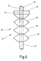
- Figure 6
- a detailed view of an additional spring according to a particular embodiment of the spring device.
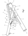
Die Figur 1 zeigt ein Dachfenster 1 in Seitenansicht,
das sich in geöffneter Schwingposition befindet.
Das Dachfenster 1 ist als Klapp-Schwingflügel-Dachfenster
ausgebildet. Es weist einen Blendrahmen
2 und einen Flügelrahmen 3 auf. Der für den
Einbau in eine nicht dargestellte Dachhaut vorgesehene
Blendrahmen 2 besitzt zwei parallel zueinander
beabstandet verlaufende Längsholme 4 und zwei ebenfalls
parallel beabstandet zueinander verlaufende
Querholme 5. Entsprechend ist der Flügelrahmen 3
mit zwei parallel beabstandet zueinander verlaufenden
Längsholmen 6 sowie zwei parallel beabstandet
zueinander verlaufenden Querholmen 7 ausgestattet.
Mittels eines Betätigungsgriffs 8, der am unteren
Querholm 7 des Flügelrahmens 3 angeordnet ist, läßt
sich das Dachfenster 1 manuell betätigen. Den oberen,
etwa hälftigen Abschnitten 9 der beiden Längsholme
6 des Flügelrahmens 3 sind Hilfsrahmenprofile
10 zugeordnet, die am Blendrahmen 2 im Bereich des
oberen Querholms 5 um eine horizontale Achse 11 und
am Flügelrahmen 3 um eine horizontale Achse 12
schwenkbar gelagert sind.1 shows a roof window 1 in side view,
which is in the open swing position.
The roof window 1 is a hinged-wing roof window
educated. It has a
Befindet sich der Flügelrahmen 3 in Schließstellung,
so liegen die Hilfsrahmenprofile 10 parallel
auf den Längsholmen 6 auf und sind in dieser Position
fixiert. Wird der Betätigungsgriff 8 in Klappposition
verschwenkt, so bleiben die Hilfsrahmenprofile
10 mit den Längsholmen 6 parallel gekoppelt,
und es ist ein Verschwenken des Flügelrahmens
3 um die Achse 11 in Klappstellung möglich. Wird
der Betätigungsgriff 8 in Schwingposition verlagert
und das Fenster geöffnet, so wird die in der Figur
1 gezeichnete Stellung eingenommen. In dieser liegt
eine Entkopplung der Hilfsrahmenprofile 10 von den
Längsholmen 6 des Flügelrahmens 3 vor, so daß diese
um die Achse 12 in eine Winkelposition zueinander
gelangen, wobei die Hilfsrahmenprofile 10 um die
Achse 11 einen Winkel α zum Blendrahmen 2 einnehmen
und der Flügelrahmen 3 um die Achse 12 relativ zu
den Hilfsrahmenprofilen 10 verschwenkt ist. Die
Achse 12 bildet somit eine Schwingachse, die es erlaubt,
maximal etwa eine 180°-Drehung des Flügelrahmens
3 vorzunehmen, wodurch die Außenseite des
Flügelrahmens 3 dem Blendrahmen zugekehrt wird, so
daR beispielsweise die Außenseite der Verglasung
vom Raum her gereinigt werden kann. Zur Führung der
Schwingbewegung des Flügelrahmens 3 am Blendrahmen
2 sind Führungszapfen 13 vorgesehen, die an den
Längsholmen 6 des Flügelrahmens 3 angeordnet sind
und in Längsführungen 14 an den Längsholmen 6 des
Blendrahmen 2 angreifen. An jedem Längsholm 6 des
Flügelrahmens 3 ist schwenkbeweglich um eine Achse
15 jeweils eine Federvorrichtung 16 angeordnet, die
eine Schwinghilfe 17 bildet. Alternativ ist es auch
möglich, daß eine derartige Federvorrichtung 16 nur
an einem der Längsholme 6 des Fensterflügels 1 angeordnet
ist. Die Federvorrichtung 16 ist als axial
wirkendes Federelement, nämlich als Teleskopfederelement
18 ausgestaltet, so daR entgegen einer Rückstellkraft,
die durch das Gewicht des Fensterflügels
bewirkt ist, das Bestreben besteht, möglichst
eine maximale Länge einzunehmen. Das Teleskopfederelement
18 weist ein Gehäuse 19 auf, in dem sich
eine nicht dargestellte Schraubendruckfeder befindet.
Vom Gehäuse 19 geht axial eine feststehende
Stütze 20 aus, die ein freies Ende 21 aufweist. Das
freie Ende 21 bildet ein erstes Ende 22 der Federvorrichtung
16. Auf dem der Stütze 20 gegenüberliegenden
Ende des Gehäuses 19 tritt eine axial
bewegliche Betätigungsstange 23' aus, die eine Kolbenstange
23 bildet, welche mittels der nicht dargestellten,
sich innerhalb des Gehäuses 19 befindlichen
Schraubendruckfeder axial in Austrittsposition
vorgespannt ist.If the
Alternativ zur Ausbildung der Federvorrichtung 16
als mit Schraubendruckfeder versehene mechanische
Einrichtung ist auch möglich, daß die Federvorrichtung
eine Gasdruckfeder aufweist, wobei der Zylinder
der Gasdruckfeder von dem Gehäuse 19 und die
Betätigungsstange 23' von der Kolbenstange 23 der
Gasdruckfeder gebildet ist.As an alternative to forming the
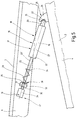
Am Ende der Kolbenstange 23 befindet sich ein Kolbenstangenkopf
24, der ein zweites Ende 41 der Federvorrichtung
16 bildet, wobei der Kolbenstangenkopf
24 mittels der Achse 15 schwenkbeweglich am
zugehörigen Längsholm 6 des Fensterflügels 3 gelagert
ist. Die Kolbenstange 23 kann in axialer Richtung
in das Gehäuse 19 ein- beziehungsweise aus dem
Gehäuse 19 ausfedern. Das freie Ende 21 ist vorzugsweise
verrundet ausgebildet. Es wirkt in der
Öffnungsphase des Flügelrahmens 3 mit einem Gegenlager
25 zusammen, das am zugehörigen Längsholm 4
des Blendrahmens 2 angeordnet und vorzugsweise nach
Art einer Gelenkpfanne 26 ausgebildet ist, in die
das freie Ende 21 lösbar eingreift. Dies ist in der
Figur 1 ersichtlich.At the end of the
Aufgrund der sich im Gehäuse 19 befindlichen, nicht
näher dargestellten Schraubendruckfeder oder -nach
dem erwähnten anderen Ausführungsbeispiel- aufgrund
der Ausbildung des Gehäuses als Zylinder einer Gasdruckfeder,
in dem sich ein mit der Kolbenstange 23
verbundener Kolben bewegt, wird eine Hauptfeder 27
der Federvorrichtung 16 ausgebildet. Diese Hauptfeder
27 wirkt über die gesamte Ausfahrlänge der Kolbenstange
23. Bei einem Vergleich der Figuren 1 und
2 ist ersichtlich, daß die Ausfahrlänge begrenzt
ist, daß also ab einem bestimmten Öffnungswinkel
des Flügelrahmens 3 das freie Ende 21 der Federvorrichtung
16 aus dem Gegenlager 25 austritt. Der
Hauptfeder 27 ist eine Zusatzfeder 28 zugeordnet.
Aus den Figuren ist ersichtlich, daß die Zusatzfeder
28 als Schraubendruckfeder 29 ausgebildet
ist, die die Kolbenstange 23 umwendelt. Alternativ
sind jedoch auch andere Ausgestaltungen der Zusatzfeder
denkbar, zum Beispiel als mechanische Feder,
die parallel zur Hauptfeder angeordnet ist oder als
Gasdruckfeder. Gemäß der Figuren 3 bis 5 ist ersichtlich,
daß die Kolbenstange 23 im Bereich ihres
Kolbenstangenkopfes 24 ein Außengewinde 30 aufweist,
auf das ein mit Innengewinde 31 versehenes
Anlageelement 32 aufgeschraubt ist. Durch Verdrehen
des Anlageelements 32 läßt sich dessen axiale Lage
auf der Kolbenstange 23 verstellen. Die Zusatzfeder
28 ist derart auf der Kolbenstange 23 angeordnet,
daß sie sich zwischen der Stirnseite 33 des Gehäuses
19 und dem Anlageelement 32 befindet, das
heißt, daß sich die Zusatzfeder 28 mit einem Ende
34 am Zylinder 19 und mit dem anderen Ende 35 an
dem Anlageelement 32 abstützt. Diese Abstützung erfolgt
jedoch nur über einen Abschnitt des gesamten
Stellwegs der Federvorrichtung 16. Ist die Federvorrichtung
16 relativ stark zusammengedrückt, so
wirken daher Hauptfeder 27 und Zusatzfeder 28 gemeinsam,
das heißt, die Federvorrichtung weist eine
erhöhte Federkraft auf. Ist die Kolbenstange 23 relativ
weit aus dem Gehäuse 19 ausgetreten, so hat
sich das Anlageelement 32 entsprechend weit von der
Stirnseite 33 des Gehäuses 19 entfernt. Ist diese
Entfernung größer als die Länge der Zusatzfeder 28
in ihrem entspannten Zustand, so wirkt die Zusatzfeder
28 nicht mehr, das heißt, die Hauptfeder 27
wird nicht mehr unterstützt, so daß die Hauptfeder
27 allein die weitere Ausfahrbewegung der Kolbenstange
23 bis in die Endposition bewirkt.Because of the located in the
Aus der Figur 6 ist ersichtlich, daß die Zusatzfeder
28 auch von einzelnen Tellerfederelementen 36
gebildet sein kann, die jeweils mittels eines
Durchbruchs auf die Kolbenstange 23 aufgereiht
sind. Die einzelnen Tellerfederelemente 36 können
auch zusammenhängend aneinander ausgebildet sein.
Insgesamt wird dadurch eine Tellerfeder 37 gebildet,
die die in Figur 6 nicht dargestellte Hauptfeder
unterstützt. Die axial federnden Tellerfederelemente
36 sind aus elastischem Material, beispielsweise
aus Federstahl oder aus elastischem
Kunststoff oder dergleichen, hergestellt.From Figure 6 it can be seen that the
Es ergibt sich folgende Funktion: Aus der Figur 3
ist ersichtlich, daß sich das Dachfenster in geschlossener
Stellung befindet. In dieser Stellung
ist die Federvorrichtung 16 maximal axial zusammengeschoben,
das heißt, sie befindet sich in vorgespannter
Stellung, in der sich das freie Ende 21 an
dem Gegenlager 25 abstützt. Wird der Betätigungsgriff
8 von einer Bedienperson in Schwingposition
bewegt und das Dachfenster 1 geöffnet, so wird
diese Öffnungsbewegung durch die Federkraft der Federvorrichtung
16 unterstützt, wobei der Anfangsöffnungsweg,
also ein Abschnitt des gesamten Stellwegs,
von den von der Hauptfeder 27 und von der Zusatzfeder
28 aufgebrachten Kräften unterstützt
wird. Da die beiden Federn 27 und 28 "parallel geschaltet"
sind, addieren sich die Federkräfte und
unterstützen die Öffnungsbewegung entsprechend
stark, was deshalb besonders günstig ist, weil die
die Öffnungsbewegung unterstützende Kraftkomponente
der Gesamtanordnung aufgrund der nur geringen
Schräglage der Längsachse der Federvorrichtung relativ
zur Längserstreckung der Längsholme 4 entsprechend
klein ist. Wird das Dachfenster 1 im Zuge
des Öffnungsvorgangs weiter verstellt, so wird die
Position gemäß der Figur 4 erreicht, die eine Ausfahrstellung
der Betätigungsstange 23' zeigt, in
der die Zusatzfeder 28 maximal entspannt ist, das
heißt gerade ihre Wirkung aufhört. Wird das Dachfenster
1 noch weiter geöffnet, beispielsweise bis
in die Position der Figur 5, so ist ersichtlich,
daR die Zusatzfeder 28 eine Länge aufweist, die
kleiner ist als der Abstand der Stirnseite 33 vom
Anlageelement 32, das heißt, es wirkt nur noch die
Hauptfeder 27, die eine entsprechend kleinere Kraft
auf den Flügelrahmen 3 ausübt, was jedoch aufgrund
der jetzt günstigeren Hebelverhältnisse zu einer
ausgewogenen Abstützung führt. Die günstigeren Hebelverhältnisse
haben sich deshalb eingestellt,
weil sich der zwischen der Längsachse der Federvorrichtung
16 und der Längserstreckung der Längsholme
6 eingeschlossene Winkel vergrößert hat. Wird das
Dachfenster 1 noch weiter geöffnet, beispielsweise
bis in die Position der Figur 2, so wirkt die Federvorrichtung
16 nicht mehr unterstützend, da ihr
freies Ende 21 aus dem Gegenlager 25 austritt. Dieses
ist gewollt, da in der weit geöffneten Position
keine Unterstützung durch die Federvorrichtung 16
notwendig ist.The following function results: from FIG. 3
it can be seen that the roof window is in the closed position
Position. In this position
the
Claims (15)
Priority Applications (2)
| Application Number | Priority Date | Filing Date | Title |
|---|---|---|---|
| SI9830689T SI0872610T1 (en) | 1997-04-16 | 1998-03-11 | Roof window |
| DK98104386T DK0872610T3 (en) | 1997-04-16 | 1998-03-11 | skylight |
Applications Claiming Priority (2)
| Application Number | Priority Date | Filing Date | Title |
|---|---|---|---|
| DE19715860A DE19715860B4 (en) | 1997-04-16 | 1997-04-16 | skylight |
| DE19715860 | 1997-04-16 |
Publications (3)
| Publication Number | Publication Date |
|---|---|
| EP0872610A2 true EP0872610A2 (en) | 1998-10-21 |
| EP0872610A3 EP0872610A3 (en) | 1999-06-09 |
| EP0872610B1 EP0872610B1 (en) | 2004-07-14 |
Family
ID=7826674
Family Applications (1)
| Application Number | Title | Priority Date | Filing Date |
|---|---|---|---|
| EP98104386A Expired - Lifetime EP0872610B1 (en) | 1997-04-16 | 1998-03-11 | Roof window |
Country Status (9)
| Country | Link |
|---|---|
| EP (1) | EP0872610B1 (en) |
| AT (1) | ATE271167T1 (en) |
| CZ (1) | CZ293881B6 (en) |
| DE (2) | DE19715860B4 (en) |
| DK (1) | DK0872610T3 (en) |
| ES (1) | ES2226019T3 (en) |
| HU (1) | HU222364B1 (en) |
| PL (1) | PL185795B1 (en) |
| SI (1) | SI0872610T1 (en) |
Cited By (6)
| Publication number | Priority date | Publication date | Assignee | Title |
|---|---|---|---|---|
| EP1293632A2 (en) * | 2001-09-12 | 2003-03-19 | Bayerische Motoren Werke Aktiengesellschaft | Spring system for a pivoting rear door of a vehicle |
| EP1508663A1 (en) * | 2003-08-20 | 2005-02-23 | VKR Holding A/S | An improved pivot window with at least one auxiliary opening device |
| WO2005019574A1 (en) * | 2003-08-20 | 2005-03-03 | Vkr Holding A/S | An improved pivot window with at least one auxiliary opening device and check means |
| EP1813753A1 (en) * | 2006-01-31 | 2007-08-01 | Roto Frank Ag | Roof window |
| EP2003263A2 (en) | 2007-06-11 | 2008-12-17 | Dobroplast, Renate Kaczynska | Device for fixing the position of a roof window wing |
| EP2806089A1 (en) * | 2013-05-22 | 2014-11-26 | Roto Frank Ag | Assembly for assisting an opening movement of a leaf of a window or a door |
Families Citing this family (2)
| Publication number | Priority date | Publication date | Assignee | Title |
|---|---|---|---|---|
| DE102009042756B4 (en) | 2008-10-02 | 2019-06-27 | Stabilus Gmbh | gas spring |
| US20140202084A1 (en) * | 2012-06-08 | 2014-07-24 | QinetiQ North America, Inc. | Emergency egress system |
Citations (1)
| Publication number | Priority date | Publication date | Assignee | Title |
|---|---|---|---|---|
| DE7416262U (en) | 1974-05-09 | 1974-10-03 | Hirz E Kg | SLOPING ROOF WINDOW |
Family Cites Families (7)
| Publication number | Priority date | Publication date | Assignee | Title |
|---|---|---|---|---|
| DE714826C (en) * | 1938-08-11 | 1941-12-08 | Diessel Maschinen Und Appbau G | Hinged lid balancing |
| US3851907A (en) * | 1973-04-26 | 1974-12-03 | Gen Motors Corp | Telescopic counterbalance |
| US4623132A (en) * | 1985-02-27 | 1986-11-18 | Fichtel & Sachs Industries, Inc. | Gas spring counterbalance system |
| DE3718040A1 (en) * | 1987-05-28 | 1988-12-15 | Frank Gmbh Wilh | ROOF WINDOW |
| DE8816626U1 (en) * | 1988-05-20 | 1990-01-25 | Heim Und Haus Vertriebsgesellschaft Fuer Kunststoffenster Und -Rollaeden Mbh, 4100 Duisburg, De | |
| DE4038567A1 (en) * | 1990-12-04 | 1992-06-11 | Krantz H Gmbh & Co | DEVICE FOR COMPENSATING THE WEIGHT OF A CEILING PART |
| DK170718B1 (en) * | 1993-12-10 | 1995-12-18 | Rasmussen Kann Ind As | Window, especially for installation in a sloping roof surface |
-
1997
- 1997-04-16 DE DE19715860A patent/DE19715860B4/en not_active Expired - Fee Related
-
1998
- 1998-03-11 EP EP98104386A patent/EP0872610B1/en not_active Expired - Lifetime
- 1998-03-11 ES ES98104386T patent/ES2226019T3/en not_active Expired - Lifetime
- 1998-03-11 SI SI9830689T patent/SI0872610T1/en unknown
- 1998-03-11 AT AT98104386T patent/ATE271167T1/en active
- 1998-03-11 DK DK98104386T patent/DK0872610T3/en active
- 1998-03-11 DE DE59811661T patent/DE59811661D1/en not_active Expired - Lifetime
- 1998-04-15 PL PL98325804A patent/PL185795B1/en unknown
- 1998-04-15 CZ CZ19981135A patent/CZ293881B6/en not_active IP Right Cessation
- 1998-04-15 HU HU9800880A patent/HU222364B1/en not_active IP Right Cessation
Patent Citations (1)
| Publication number | Priority date | Publication date | Assignee | Title |
|---|---|---|---|---|
| DE7416262U (en) | 1974-05-09 | 1974-10-03 | Hirz E Kg | SLOPING ROOF WINDOW |
Cited By (11)
| Publication number | Priority date | Publication date | Assignee | Title |
|---|---|---|---|---|
| EP1293632A2 (en) * | 2001-09-12 | 2003-03-19 | Bayerische Motoren Werke Aktiengesellschaft | Spring system for a pivoting rear door of a vehicle |
| EP1293632A3 (en) * | 2001-09-12 | 2005-12-28 | Bayerische Motoren Werke Aktiengesellschaft | Spring system for a pivoting rear door of a vehicle |
| EP1508663A1 (en) * | 2003-08-20 | 2005-02-23 | VKR Holding A/S | An improved pivot window with at least one auxiliary opening device |
| WO2005019574A1 (en) * | 2003-08-20 | 2005-03-03 | Vkr Holding A/S | An improved pivot window with at least one auxiliary opening device and check means |
| EA007727B1 (en) * | 2003-08-20 | 2006-12-29 | Вкр Холдинг А/С | An improved pivot window with at least one auxiliary opening device and check means |
| EP2280143A3 (en) * | 2003-08-20 | 2011-04-27 | VKR Holding A/S | An improved pivot window with at least one auxiliary opening device |
| EP1813753A1 (en) * | 2006-01-31 | 2007-08-01 | Roto Frank Ag | Roof window |
| EP2003263A2 (en) | 2007-06-11 | 2008-12-17 | Dobroplast, Renate Kaczynska | Device for fixing the position of a roof window wing |
| EP2003263A3 (en) * | 2007-06-11 | 2009-08-12 | Dobroplast, Renate Kaczynska | Device for fixing the position of a roof window wing |
| EP2806089A1 (en) * | 2013-05-22 | 2014-11-26 | Roto Frank Ag | Assembly for assisting an opening movement of a leaf of a window or a door |
| WO2014187753A1 (en) * | 2013-05-22 | 2014-11-27 | Roto Frank Ag | Arrangement for supporting an opening movement of a leaf of a window or a door, and window or door |
Also Published As
| Publication number | Publication date |
|---|---|
| ES2226019T3 (en) | 2005-03-16 |
| DE19715860A1 (en) | 1998-10-29 |
| EP0872610A3 (en) | 1999-06-09 |
| EP0872610B1 (en) | 2004-07-14 |
| ATE271167T1 (en) | 2004-07-15 |
| SI0872610T1 (en) | 2004-12-31 |
| CZ113598A3 (en) | 1998-11-11 |
| PL325804A1 (en) | 1998-10-26 |
| PL185795B1 (en) | 2003-07-31 |
| DK0872610T3 (en) | 2004-11-22 |
| DE19715860B4 (en) | 2005-11-03 |
| DE59811661D1 (en) | 2004-08-19 |
| HU222364B1 (en) | 2003-06-28 |
| HU9800880D0 (en) | 1998-06-29 |
| HUP9800880A1 (en) | 1998-12-28 |
| CZ293881B6 (en) | 2004-08-18 |
Similar Documents
| Publication | Publication Date | Title |
|---|---|---|
| AT502611B1 (en) | HINGE | |
| DE3118641C2 (en) | hinge | |
| DE1934912C3 (en) | Automatic door closer | |
| DE2648344A1 (en) | FITTINGS FOR SLIDING WINDOWS, SLIDING DOORS, ETC. | |
| EP0872610B1 (en) | Roof window | |
| DE2556575B2 (en) | Skylight | |
| EP3045634B1 (en) | Checking device for a window or a door comprising an energy storage device | |
| EP0972885B1 (en) | Tilting roof window | |
| DE19650190B4 (en) | Roof windows, in particular swing-wing roof windows | |
| DE19518253A1 (en) | Compression device between rotary door or window leaf and fixed frame | |
| DE1810671B2 (en) | Aligning device for closing windows and doors - uses roller for aligning moving and fixed frame | |
| DE102020207128B3 (en) | Hinge with integrated shock absorber | |
| DE602004007009T2 (en) | IMPROVED KIPPFENSTER WITH LOCKING | |
| DE202005009745U1 (en) | fitting assembly | |
| DE2407586B1 (en) | Skylight pivotable about an upper horizontal axis | |
| DE2443036C3 (en) | Opening device | |
| EP1273755A2 (en) | Insect screen | |
| DE2421919C3 (en) | window | |
| DE19825071C2 (en) | Parallel opening window with rotating function | |
| DE19600948C1 (en) | Equipment to balance weight of skylight window | |
| DE10002532B4 (en) | Drive for a rotatably mounted on a stationary frame wings of a window, a door or the like | |
| DE2548989A1 (en) | Combined tilting and rotating window - has closing torsion spring between moving and fixed frame profiles | |
| EP1400648A2 (en) | System for opening and closing of lids, especially of tailgates of motor vehicles | |
| EP2690241B1 (en) | Fitting for a parallel set sliding door or a parallel set sliding window | |
| DE19717193A1 (en) | Sloping roof hinged swing window |
Legal Events
| Date | Code | Title | Description |
|---|---|---|---|
| PUAI | Public reference made under article 153(3) epc to a published international application that has entered the european phase |
Free format text: ORIGINAL CODE: 0009012 |
|
| AK | Designated contracting states |
Kind code of ref document: A2 Designated state(s): AT BE CH DE DK ES FR GB IT LI NL |
|
| AX | Request for extension of the european patent |
Free format text: AL;LT;LV;MK;RO;SI |
|
| PUAL | Search report despatched |
Free format text: ORIGINAL CODE: 0009013 |
|
| AK | Designated contracting states |
Kind code of ref document: A3 Designated state(s): AT BE CH DE DK ES FI FR GB GR IE IT LI LU MC NL PT SE |
|
| AX | Request for extension of the european patent |
Free format text: AL;LT;LV;MK;RO;SI |
|
| 17P | Request for examination filed |
Effective date: 19990514 |
|
| AKX | Designation fees paid |
Free format text: AT BE CH DE DK ES FR GB IT LI NL |
|
| AXX | Extension fees paid |
Free format text: LT PAYMENT 19990827;LV PAYMENT 19990827;SI PAYMENT 19990827 |
|
| 17Q | First examination report despatched |
Effective date: 20021213 |
|
| GRAP | Despatch of communication of intention to grant a patent |
Free format text: ORIGINAL CODE: EPIDOSNIGR1 |
|
| GRAS | Grant fee paid |
Free format text: ORIGINAL CODE: EPIDOSNIGR3 |
|
| GRAA | (expected) grant |
Free format text: ORIGINAL CODE: 0009210 |
|
| AK | Designated contracting states |
Kind code of ref document: B1 Designated state(s): AT BE CH DE DK ES FR GB IT LI NL |
|
| AX | Request for extension of the european patent |
Extension state: LT LV SI |
|
| REG | Reference to a national code |
Ref country code: GB Ref legal event code: FG4D Free format text: NOT ENGLISH |
|
| REG | Reference to a national code |
Ref country code: CH Ref legal event code: EP |
|
| REF | Corresponds to: |
Ref document number: 59811661 Country of ref document: DE Date of ref document: 20040819 Kind code of ref document: P |
|
| REG | Reference to a national code |
Ref country code: CH Ref legal event code: NV Representative=s name: E. BLUM & CO. PATENTANWAELTE |
|
| REG | Reference to a national code |
Ref country code: DK Ref legal event code: T3 |
|
| GBT | Gb: translation of ep patent filed (gb section 77(6)(a)/1977) | ||
| REG | Reference to a national code |
Ref country code: SI Ref legal event code: IF |
|
| REG | Reference to a national code |
Ref country code: ES Ref legal event code: FG2A Ref document number: 2226019 Country of ref document: ES Kind code of ref document: T3 |
|
| ET | Fr: translation filed | ||
| PLBE | No opposition filed within time limit |
Free format text: ORIGINAL CODE: 0009261 |
|
| STAA | Information on the status of an ep patent application or granted ep patent |
Free format text: STATUS: NO OPPOSITION FILED WITHIN TIME LIMIT |
|
| 26N | No opposition filed |
Effective date: 20050415 |
|
| REG | Reference to a national code |
Ref country code: CH Ref legal event code: PFA Owner name: ROTO FRANK AKTIENGESELLSCHAFT Free format text: ROTO FRANK AKTIENGESELLSCHAFT#STUTTGARTER STRASSE 145-149#70771 LEINFELDEN-ECHTERDINGEN (DE) -TRANSFER TO- ROTO FRANK AKTIENGESELLSCHAFT#STUTTGARTER STRASSE 145-149#70771 LEINFELDEN-ECHTERDINGEN (DE) |
|
| PGFP | Annual fee paid to national office [announced via postgrant information from national office to epo] |
Ref country code: ES Payment date: 20080310 Year of fee payment: 11 |
|
| REG | Reference to a national code |
Ref country code: ES Ref legal event code: FD2A Effective date: 20090312 |
|
| PG25 | Lapsed in a contracting state [announced via postgrant information from national office to epo] |
Ref country code: ES Free format text: LAPSE BECAUSE OF NON-PAYMENT OF DUE FEES Effective date: 20090312 |
|
| PGFP | Annual fee paid to national office [announced via postgrant information from national office to epo] |
Ref country code: DK Payment date: 20140325 Year of fee payment: 17 Ref country code: NL Payment date: 20140320 Year of fee payment: 17 |
|
| PGFP | Annual fee paid to national office [announced via postgrant information from national office to epo] |
Ref country code: IT Payment date: 20140326 Year of fee payment: 17 Ref country code: FR Payment date: 20140319 Year of fee payment: 17 |
|
| PGFP | Annual fee paid to national office [announced via postgrant information from national office to epo] |
Ref country code: GB Payment date: 20140324 Year of fee payment: 17 |
|
| PGFP | Annual fee paid to national office [announced via postgrant information from national office to epo] |
Ref country code: BE Payment date: 20140320 Year of fee payment: 17 |
|
| REG | Reference to a national code |
Ref country code: LT Ref legal event code: MM9D Effective date: 20150311 Ref country code: DK Ref legal event code: EBP Effective date: 20150331 |
|
| GBPC | Gb: european patent ceased through non-payment of renewal fee |
Effective date: 20150311 |
|
| REG | Reference to a national code |
Ref country code: NL Ref legal event code: MM Effective date: 20150401 |
|
| PG25 | Lapsed in a contracting state [announced via postgrant information from national office to epo] |
Ref country code: IT Free format text: LAPSE BECAUSE OF NON-PAYMENT OF DUE FEES Effective date: 20150311 |
|
| REG | Reference to a national code |
Ref country code: SI Ref legal event code: KO00 Effective date: 20151113 |
|
| REG | Reference to a national code |
Ref country code: FR Ref legal event code: ST Effective date: 20151130 |
|
| PG25 | Lapsed in a contracting state [announced via postgrant information from national office to epo] |
Ref country code: GB Free format text: LAPSE BECAUSE OF NON-PAYMENT OF DUE FEES Effective date: 20150311 |
|
| PG25 | Lapsed in a contracting state [announced via postgrant information from national office to epo] |
Ref country code: FR Free format text: LAPSE BECAUSE OF NON-PAYMENT OF DUE FEES Effective date: 20150331 |
|
| PG25 | Lapsed in a contracting state [announced via postgrant information from national office to epo] |
Ref country code: DK Free format text: LAPSE BECAUSE OF NON-PAYMENT OF DUE FEES Effective date: 20150331 |
|
| PGFP | Annual fee paid to national office [announced via postgrant information from national office to epo] |
Ref country code: CH Payment date: 20160322 Year of fee payment: 19 |
|
| PGFP | Annual fee paid to national office [announced via postgrant information from national office to epo] |
Ref country code: AT Payment date: 20160318 Year of fee payment: 19 |
|
| PGFP | Annual fee paid to national office [announced via postgrant information from national office to epo] |
Ref country code: DE Payment date: 20170327 Year of fee payment: 20 |
|
| PG25 | Lapsed in a contracting state [announced via postgrant information from national office to epo] |
Ref country code: NL Free format text: LAPSE BECAUSE OF NON-PAYMENT OF DUE FEES Effective date: 20150401 |
|
| PG25 | Lapsed in a contracting state [announced via postgrant information from national office to epo] |
Ref country code: BE Free format text: LAPSE BECAUSE OF NON-PAYMENT OF DUE FEES Effective date: 20150331 |
|
| REG | Reference to a national code |
Ref country code: CH Ref legal event code: PL |
|
| REG | Reference to a national code |
Ref country code: AT Ref legal event code: MM01 Ref document number: 271167 Country of ref document: AT Kind code of ref document: T Effective date: 20170311 |
|
| PG25 | Lapsed in a contracting state [announced via postgrant information from national office to epo] |
Ref country code: AT Free format text: LAPSE BECAUSE OF NON-PAYMENT OF DUE FEES Effective date: 20170311 |
|
| PG25 | Lapsed in a contracting state [announced via postgrant information from national office to epo] |
Ref country code: CH Free format text: LAPSE BECAUSE OF NON-PAYMENT OF DUE FEES Effective date: 20170331 Ref country code: LI Free format text: LAPSE BECAUSE OF NON-PAYMENT OF DUE FEES Effective date: 20170331 |
|
| REG | Reference to a national code |
Ref country code: DE Ref legal event code: R071 Ref document number: 59811661 Country of ref document: DE |