EP2003263A2 - Device for fixing the position of a roof window wing - Google Patents
Device for fixing the position of a roof window wing Download PDFInfo
- Publication number
- EP2003263A2 EP2003263A2 EP08460023A EP08460023A EP2003263A2 EP 2003263 A2 EP2003263 A2 EP 2003263A2 EP 08460023 A EP08460023 A EP 08460023A EP 08460023 A EP08460023 A EP 08460023A EP 2003263 A2 EP2003263 A2 EP 2003263A2
- Authority
- EP
- European Patent Office
- Prior art keywords
- window
- guide rail
- wing
- window frame
- roll
- Prior art date
- Legal status (The legal status is an assumption and is not a legal conclusion. Google has not performed a legal analysis and makes no representation as to the accuracy of the status listed.)
- Granted
Links
- 230000000903 blocking effect Effects 0.000 description 1
Images
Classifications
-
- E—FIXED CONSTRUCTIONS
- E04—BUILDING
- E04D—ROOF COVERINGS; SKY-LIGHTS; GUTTERS; ROOF-WORKING TOOLS
- E04D13/00—Special arrangements or devices in connection with roof coverings; Protection against birds; Roof drainage ; Sky-lights
- E04D13/03—Sky-lights; Domes; Ventilating sky-lights
- E04D13/035—Sky-lights; Domes; Ventilating sky-lights characterised by having movable parts
- E04D13/0357—Sky-lights; Domes; Ventilating sky-lights characterised by having movable parts the parts pivoting about an axis supported on a hinged frame or arms
-
- E—FIXED CONSTRUCTIONS
- E05—LOCKS; KEYS; WINDOW OR DOOR FITTINGS; SAFES
- E05D—HINGES OR SUSPENSION DEVICES FOR DOORS, WINDOWS OR WINGS
- E05D15/00—Suspension arrangements for wings
- E05D15/40—Suspension arrangements for wings supported on arms movable in vertical planes
- E05D15/406—Suspension arrangements for wings supported on arms movable in vertical planes with pivoted arms and sliding guides
-
- E—FIXED CONSTRUCTIONS
- E05—LOCKS; KEYS; WINDOW OR DOOR FITTINGS; SAFES
- E05F—DEVICES FOR MOVING WINGS INTO OPEN OR CLOSED POSITION; CHECKS FOR WINGS; WING FITTINGS NOT OTHERWISE PROVIDED FOR, CONCERNED WITH THE FUNCTIONING OF THE WING
- E05F3/00—Closers or openers with braking devices, e.g. checks; Construction of pneumatic or liquid braking devices
- E05F3/18—Closers or openers with braking devices, e.g. checks; Construction of pneumatic or liquid braking devices with counteracting springs
-
- E—FIXED CONSTRUCTIONS
- E05—LOCKS; KEYS; WINDOW OR DOOR FITTINGS; SAFES
- E05F—DEVICES FOR MOVING WINGS INTO OPEN OR CLOSED POSITION; CHECKS FOR WINGS; WING FITTINGS NOT OTHERWISE PROVIDED FOR, CONCERNED WITH THE FUNCTIONING OF THE WING
- E05F1/00—Closers or openers for wings, not otherwise provided for in this subclass
- E05F1/08—Closers or openers for wings, not otherwise provided for in this subclass spring-actuated, e.g. for horizontally sliding wings
- E05F1/10—Closers or openers for wings, not otherwise provided for in this subclass spring-actuated, e.g. for horizontally sliding wings for swinging wings, e.g. counterbalance
- E05F1/1041—Closers or openers for wings, not otherwise provided for in this subclass spring-actuated, e.g. for horizontally sliding wings for swinging wings, e.g. counterbalance with a coil spring perpendicular to the pivot axis
- E05F1/105—Closers or openers for wings, not otherwise provided for in this subclass spring-actuated, e.g. for horizontally sliding wings for swinging wings, e.g. counterbalance with a coil spring perpendicular to the pivot axis with a compression spring
- E05F1/1058—Closers or openers for wings, not otherwise provided for in this subclass spring-actuated, e.g. for horizontally sliding wings for swinging wings, e.g. counterbalance with a coil spring perpendicular to the pivot axis with a compression spring for counterbalancing
-
- E—FIXED CONSTRUCTIONS
- E05—LOCKS; KEYS; WINDOW OR DOOR FITTINGS; SAFES
- E05Y—INDEXING SCHEME ASSOCIATED WITH SUBCLASSES E05D AND E05F, RELATING TO CONSTRUCTION ELEMENTS, ELECTRIC CONTROL, POWER SUPPLY, POWER SIGNAL OR TRANSMISSION, USER INTERFACES, MOUNTING OR COUPLING, DETAILS, ACCESSORIES, AUXILIARY OPERATIONS NOT OTHERWISE PROVIDED FOR, APPLICATION THEREOF
- E05Y2900/00—Application of doors, windows, wings or fittings thereof
- E05Y2900/10—Application of doors, windows, wings or fittings thereof for buildings or parts thereof
- E05Y2900/13—Type of wing
- E05Y2900/148—Windows
- E05Y2900/152—Roof windows
Definitions
- the subject of the present invention is a device for fixing the position of a roof window wing.
- Polish patent no. PL-177697 discloses a roof window with a fixing device for blocking opening positions, comprising a support in a form of a flexible arm, angularly movable with respect to the window frame, which is connected to a window frame and to a window wing, whereas the ending of the arm is provided with a roll actuated by a spring located in a window frame guide.
- European patent application EP 0 872 610 discloses a roof window having a movable wing, which is connected to the window frame by means of an arm supported rotationally in the window frame, and an axle located in a window frame guide,
- the frame of the window wing is also connected to the window frame via a telescopic device, which is mounted pivotally in the window wing frame and the window frame guide.
- the telescopic device comprises a main spring and an auxiliary spring.
- the window wing is provided with a roll which is supported on a raceway of a window frame and, at the same time, on the face of a nut screwed onto an end of a rod slidingly disposed within a guide rail by means of an adjusting nut, whereas a spiral spring is pulled onto the rod, with the spring end faces butting up against the adjusting nut and a nut located on the other end of the rod.
- Lock nuts are disposed on a tip of the rod that protrudes beyond the guide rail.
- On the internal surface of the top wall of the guide rail a flat spring is mounted with screws, located above the roll it presses against with its offset part parallel to the raceway. The screws fixing the flat spring are rotationally mounted at the flat spring ends.
- the window frame there are beds mounted in which sliders are placed, said sliders having keys which are inserted into bed grooves, whereas arm ends are pivotally mounted to the sliders by means of pins.
- the other arm ends are pivotally mounted in the window wing frame.
- the sliders are provided with locking screws to lock the sliders within the beds, whereas the beds are provided with adjusting screws whose faces butt up against the walls of the sliders.
- This solution allows for freely opening and closing the window while it is easily possible to adjust the braking of the window wings in opening positions and it gives the possibility to adjust the tension of the spiral springs that amortise the window wing.
- This device makes it possible to lock a window open ajar in a fixed position without the necessity to make other operations. Additionally, by exerting a stronger pressure on a window wing, one can flip it to a reverse position or close it.
- the mounting of the arm to the window frame by means of the slider makes it possible to adjust the position of the window wing with respect to the window frame, which is particularly important for keeping the window seat-tight.
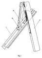
- fig. 1 depicts the window in a side view with partial cross-section
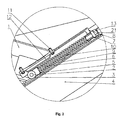
- fig.2 shows the details of the wing-to-window frame connection
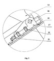
- fig. 3 shows the details of the ann-to-window frame connection
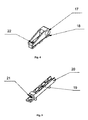
- fig.4 shows the bed in an axonometric view
- fig. 5 is the view of a slider.
- a roll 2 is mounted, which is supported on raceway 3 mounted on window frame 4 and on the face of a nut 5 screwed onto an end of rod 6 slidingly disposed within adjusting nut 7 screwed into a vertical wall 8 of the raceway 9, which is formed by the final part of the raceway 3 in the shape of a tube of rectangular cross-section.
- a spiral spring 10 mounted on rod 6, between nut 5 and adjusting nut 7, there is a spiral spring 10 mounted.
- Fixed with screws 11 to the top wall of raceway 9, a flat spring 12 is located at the initial section of the track of the roll 2 it presses against with its offset part parallel to the raceway 3.
- the screws 11 are rotationally mounted to the ends of the flat spring 12.
- the window wing I is connected to the window frame 4 by means of arms 14, one end of which is rotationally mounted on pivots 15 of wing 1, and the other end of arms 14 is rotationally mounted on pins 16 located within sliders 17.
- the sliders 17 have keys 18 located in grooves 19 of beds 20, which are fixed with screws to two corners of window frame 4. Within the transverse wall of beds 20 there are adjusting screws 21 whose faces butt up against sliders 17, and within the sliders 17 there are screws 22 whose faces are pressed against the base of beds 20.
- the roll 2 being pushed by spiral spring 10, moves between the raceway 3 and the flat spring 12, to the place where the offset part of the flat spring 12 ends. Then, the roll 2 moves away from the raceway 3 and jumps down along the slope of the flat spring 12, thus fixing the window wing 1 in such a position. To close the window wing 1. an adequate force is required.
Landscapes
- Engineering & Computer Science (AREA)
- Architecture (AREA)
- Civil Engineering (AREA)
- Structural Engineering (AREA)
- Mechanical Engineering (AREA)
- Window Of Vehicle (AREA)
- Specific Sealing Or Ventilating Devices For Doors And Windows (AREA)
- Door And Window Frames Mounted To Openings (AREA)
Abstract
Description
- The subject of the present invention is a device for fixing the position of a roof window wing.
- Polish patent no.
PL-177697 - Also, European patent application
EP 0 872 610 discloses a roof window having a movable wing, which is connected to the window frame by means of an arm supported rotationally in the window frame, and an axle located in a window frame guide, The frame of the window wing is also connected to the window frame via a telescopic device, which is mounted pivotally in the window wing frame and the window frame guide. The telescopic device comprises a main spring and an auxiliary spring. - According to the present invention, the window wing is provided with a roll which is supported on a raceway of a window frame and, at the same time, on the face of a nut screwed onto an end of a rod slidingly disposed within a guide rail by means of an adjusting nut, whereas a spiral spring is pulled onto the rod, with the spring end faces butting up against the adjusting nut and a nut located on the other end of the rod. Lock nuts are disposed on a tip of the rod that protrudes beyond the guide rail. On the internal surface of the top wall of the guide rail a flat spring is mounted with screws, located above the roll it presses against with its offset part parallel to the raceway. The screws fixing the flat spring are rotationally mounted at the flat spring ends. At the corners of the window frame there are beds mounted in which sliders are placed, said sliders having keys which are inserted into bed grooves, whereas arm ends are pivotally mounted to the sliders by means of pins. The other arm ends are pivotally mounted in the window wing frame. The sliders are provided with locking screws to lock the sliders within the beds, whereas the beds are provided with adjusting screws whose faces butt up against the walls of the sliders.
- This solution allows for freely opening and closing the window while it is easily possible to adjust the braking of the window wings in opening positions and it gives the possibility to adjust the tension of the spiral springs that amortise the window wing.
- This device makes it possible to lock a window open ajar in a fixed position without the necessity to make other operations. Additionally, by exerting a stronger pressure on a window wing, one can flip it to a reverse position or close it. The mounting of the arm to the window frame by means of the slider makes it possible to adjust the position of the window wing with respect to the window frame, which is particularly important for keeping the window seat-tight.
- The invention is disclosed in an embodiment illustrated in a drawing, where
fig. 1 depicts the window in a side view with partial cross-section,fig.2 shows the details of the wing-to-window frame connection,fig. 3 shows the details of the ann-to-window frame connection,fig.4 shows the bed in an axonometric view, andfig. 5 is the view of a slider. - As shown in the drawing, in window wing frame I a roll 2 is mounted, which is supported on
raceway 3 mounted onwindow frame 4 and on the face of a nut 5 screwed onto an end of rod 6 slidingly disposed within adjustingnut 7 screwed into avertical wall 8 of the raceway 9, which is formed by the final part of theraceway 3 in the shape of a tube of rectangular cross-section. On rod 6, between nut 5 and adjustingnut 7, there is aspiral spring 10 mounted. Fixed withscrews 11 to the top wall of raceway 9, a flat spring 12 is located at the initial section of the track of the roll 2 it presses against with its offset part parallel to theraceway 3. Thescrews 11 are rotationally mounted to the ends of the flat spring 12. On the threaded end of the rod 6, which protrudes beyond the guide rail 9, there arelock nuts 13. - The window wing I is connected to the
window frame 4 by means ofarms 14, one end of which is rotationally mounted onpivots 15 ofwing 1, and the other end ofarms 14 is rotationally mounted onpins 16 located withinsliders 17. Thesliders 17 havekeys 18 located ingrooves 19 ofbeds 20, which are fixed with screws to two corners ofwindow frame 4. Within the transverse wall ofbeds 20 there are adjustingscrews 21 whose faces butt up againstsliders 17, and within thesliders 17 there arescrews 22 whose faces are pressed against the base ofbeds 20. - When the
wing 1 is being opened, the roll 2, being pushed byspiral spring 10, moves between theraceway 3 and the flat spring 12, to the place where the offset part of the flat spring 12 ends. Then, the roll 2 moves away from theraceway 3 and jumps down along the slope of the flat spring 12, thus fixing thewindow wing 1 in such a position. To close thewindow wing 1. an adequate force is required.
Claims (4)
- Device for fixing the position of a roof window wing, which is connected to a window frame by means of an arm pivotally mounted within the wing and the window frame, while a roll mounted to the window wing frame is placed in a guide rail of the window frame, characterised in that said roll (2) is supported on raceway (3) of guide rail (9) and at the same time butts up against the face of a nut (5) screwed onto an end of rod (6) disposed slidingly within said guide rail (9) by means of adjusting nut (7), whereas on said rod (6), between adjusting nut (7) and nut (5) a spiral spring (10) is disposed, while on the internal top wall of said guide rail (9) a flat spring (12) is fixed with screws (11) and disposed above the said roll (2) it presses against with its offset middle part parallel to said raceway (3), and additionally within the final part of the longer sides of said window frame (4), there are beds (20) into which sliders (17) are inserted, said sliders having an opening for a pin (16) to which there is mounted the end of arms (14), the other end of said arms being pivotally mounted in the window wing frame (1).
- The device according to claim 1, characterised in that said sliders (17) have keys (18) placed within the grooves (19) of said beds (20), and in the base of the slides (17) there are locking screws (22).
- The device according to claim 1, characterised in that in the transverse wall of said bed (20) there is an adjusting screw (21), whose face is supported on the transverse wall of said slider (17).
- The device according to claim 1, characterised in that the screws (11) are rotationally mounted at the ends of the flat spring (12).
Applications Claiming Priority (1)
| Application Number | Priority Date | Filing Date | Title |
|---|---|---|---|
| PL382628A PL206424B1 (en) | 2007-06-11 | 2007-06-11 | Device for determination of roof window wing location |
Publications (3)
| Publication Number | Publication Date |
|---|---|
| EP2003263A2 true EP2003263A2 (en) | 2008-12-17 |
| EP2003263A3 EP2003263A3 (en) | 2009-08-12 |
| EP2003263B1 EP2003263B1 (en) | 2010-11-17 |
Family
ID=39689398
Family Applications (1)
| Application Number | Title | Priority Date | Filing Date |
|---|---|---|---|
| EP08460023A Not-in-force EP2003263B1 (en) | 2007-06-11 | 2008-06-11 | Device for fixing the position of a roof window wing |
Country Status (4)
| Country | Link |
|---|---|
| EP (1) | EP2003263B1 (en) |
| AT (1) | ATE488653T1 (en) |
| DE (1) | DE602008003482D1 (en) |
| PL (1) | PL206424B1 (en) |
Cited By (2)
| Publication number | Priority date | Publication date | Assignee | Title |
|---|---|---|---|---|
| CN110416883A (en) * | 2019-06-28 | 2019-11-05 | 熊雪根 | A kind of AC low voltage power switch box |
| PL443602A1 (en) * | 2023-01-27 | 2024-07-29 | Fakro Pp Spółka Z Ograniczoną Odpowiedzialnością | Device for lifting the roof window sash and a roof window with this device |
Citations (2)
| Publication number | Priority date | Publication date | Assignee | Title |
|---|---|---|---|---|
| EP0872610A2 (en) | 1997-04-16 | 1998-10-21 | ROTO FRANK Aktiengesellschaft | Roof window |
| PL177697B1 (en) | 1994-07-13 | 2000-01-31 | Roto Frank Ag | Roof window with a locking device |
Family Cites Families (3)
| Publication number | Priority date | Publication date | Assignee | Title |
|---|---|---|---|---|
| DE9403993U1 (en) * | 1994-03-10 | 1994-05-05 | Roto Frank Ag, 70771 Leinfelden-Echterdingen | Roof window |
| DE9406929U1 (en) * | 1994-04-26 | 1994-06-16 | Roto Frank Ag, 70771 Leinfelden-Echterdingen | Roof window |
| DE202004018472U1 (en) * | 2004-11-29 | 2005-02-10 | H. H. Heim Und Haus Holding Gmbh | Roof window, includes glide shoe fixable into position along guide using locking rail |
-
2007
- 2007-06-11 PL PL382628A patent/PL206424B1/en not_active IP Right Cessation
-
2008
- 2008-06-11 AT AT08460023T patent/ATE488653T1/en active
- 2008-06-11 DE DE602008003482T patent/DE602008003482D1/en active Active
- 2008-06-11 EP EP08460023A patent/EP2003263B1/en not_active Not-in-force
Patent Citations (2)
| Publication number | Priority date | Publication date | Assignee | Title |
|---|---|---|---|---|
| PL177697B1 (en) | 1994-07-13 | 2000-01-31 | Roto Frank Ag | Roof window with a locking device |
| EP0872610A2 (en) | 1997-04-16 | 1998-10-21 | ROTO FRANK Aktiengesellschaft | Roof window |
Cited By (2)
| Publication number | Priority date | Publication date | Assignee | Title |
|---|---|---|---|---|
| CN110416883A (en) * | 2019-06-28 | 2019-11-05 | 熊雪根 | A kind of AC low voltage power switch box |
| PL443602A1 (en) * | 2023-01-27 | 2024-07-29 | Fakro Pp Spółka Z Ograniczoną Odpowiedzialnością | Device for lifting the roof window sash and a roof window with this device |
Also Published As
| Publication number | Publication date |
|---|---|
| PL206424B1 (en) | 2010-08-31 |
| EP2003263B1 (en) | 2010-11-17 |
| PL382628A1 (en) | 2008-12-22 |
| ATE488653T1 (en) | 2010-12-15 |
| DE602008003482D1 (en) | 2010-12-30 |
| EP2003263A3 (en) | 2009-08-12 |
Similar Documents
| Publication | Publication Date | Title |
|---|---|---|
| US8764134B2 (en) | Device for opening and closing a movable part of a furniture unit | |
| CN103261554B (en) | Closing and cushioning devices for movable furniture parts | |
| CN101535586B (en) | Opening device for furniture parts which are movable relative to one another | |
| WO1992004843A1 (en) | Device for holding pushed-in drawers in the body of an item of furniture | |
| CN116194652A (en) | multi-joint hinge | |
| JP2008516109A (en) | Moving furniture member holding adjustment device | |
| WO2010095029A3 (en) | Device for moving sliding doors | |
| CN104207507B (en) | restrictive device | |
| EP2169159A2 (en) | Securing device for a door leaf | |
| US20160273254A1 (en) | Sliding door | |
| CN109681056B (en) | Slide rail device of door closer | |
| EP2003263B1 (en) | Device for fixing the position of a roof window wing | |
| CN104822296A (en) | Device for moving movable furniture part | |
| JP4836622B2 (en) | Opening / closing member closing device | |
| JP2009000505A (en) | Retractable damping device for displaceable element | |
| CN207847415U (en) | It is a kind of to push and pull the door mounting structure that be opened flat | |
| CN114867928B (en) | Arrangement system with furniture hinges and covers | |
| KR101333053B1 (en) | Slider mounting device for slide door | |
| KR101183206B1 (en) | Door apparatus for the opening angle adjustment | |
| EP2169160A3 (en) | Securing device for a door leaf | |
| TWI534334B (en) | Door closet | |
| CN107923203A (en) | Hinge and the backplate with hinge | |
| WO2022223379A1 (en) | Self-adjusting locking piece for a locking unit | |
| KR100879100B1 (en) | Car Door Checker | |
| CN219932013U (en) | Integral type flap door and sealing mechanism thereof |
Legal Events
| Date | Code | Title | Description |
|---|---|---|---|
| PUAI | Public reference made under article 153(3) epc to a published international application that has entered the european phase |
Free format text: ORIGINAL CODE: 0009012 |
|
| AK | Designated contracting states |
Kind code of ref document: A2 Designated state(s): AT BE BG CH CY CZ DE DK EE ES FI FR GB GR HR HU IE IS IT LI LT LU LV MC MT NL NO PL PT RO SE SI SK TR |
|
| AX | Request for extension of the european patent |
Extension state: AL BA MK RS |
|
| PUAL | Search report despatched |
Free format text: ORIGINAL CODE: 0009013 |
|
| AK | Designated contracting states |
Kind code of ref document: A3 Designated state(s): AT BE BG CH CY CZ DE DK EE ES FI FR GB GR HR HU IE IS IT LI LT LU LV MC MT NL NO PL PT RO SE SI SK TR |
|
| AX | Request for extension of the european patent |
Extension state: AL BA MK RS |
|
| 17P | Request for examination filed |
Effective date: 20091210 |
|
| AKX | Designation fees paid |
Designated state(s): AT BE BG CH CY CZ DE DK EE ES FI FR GB GR HR HU IE IS IT LI LT LU LV MC MT NL NO PL PT RO SE SI SK TR |
|
| GRAP | Despatch of communication of intention to grant a patent |
Free format text: ORIGINAL CODE: EPIDOSNIGR1 |
|
| GRAS | Grant fee paid |
Free format text: ORIGINAL CODE: EPIDOSNIGR3 |
|
| GRAA | (expected) grant |
Free format text: ORIGINAL CODE: 0009210 |
|
| AK | Designated contracting states |
Kind code of ref document: B1 Designated state(s): AT BE BG CH CY CZ DE DK EE ES FI FR GB GR HR HU IE IS IT LI LT LU LV MC MT NL NO PL PT RO SE SI SK TR |
|
| REG | Reference to a national code |
Ref country code: GB Ref legal event code: FG4D |
|
| REG | Reference to a national code |
Ref country code: CH Ref legal event code: EP |
|
| REG | Reference to a national code |
Ref country code: IE Ref legal event code: FG4D |
|
| REF | Corresponds to: |
Ref document number: 602008003482 Country of ref document: DE Date of ref document: 20101230 Kind code of ref document: P |
|
| REG | Reference to a national code |
Ref country code: NL Ref legal event code: VDEP Effective date: 20101117 |
|
| LTIE | Lt: invalidation of european patent or patent extension |
Effective date: 20101117 |
|
| PG25 | Lapsed in a contracting state [announced via postgrant information from national office to epo] |
Ref country code: LT Free format text: LAPSE BECAUSE OF FAILURE TO SUBMIT A TRANSLATION OF THE DESCRIPTION OR TO PAY THE FEE WITHIN THE PRESCRIBED TIME-LIMIT Effective date: 20101117 Ref country code: NO Free format text: LAPSE BECAUSE OF FAILURE TO SUBMIT A TRANSLATION OF THE DESCRIPTION OR TO PAY THE FEE WITHIN THE PRESCRIBED TIME-LIMIT Effective date: 20110217 |
|
| REG | Reference to a national code |
Ref country code: SK Ref legal event code: T3 Ref document number: E 8813 Country of ref document: SK |
|
| PG25 | Lapsed in a contracting state [announced via postgrant information from national office to epo] |
Ref country code: IS Free format text: LAPSE BECAUSE OF FAILURE TO SUBMIT A TRANSLATION OF THE DESCRIPTION OR TO PAY THE FEE WITHIN THE PRESCRIBED TIME-LIMIT Effective date: 20110317 Ref country code: CY Free format text: LAPSE BECAUSE OF FAILURE TO SUBMIT A TRANSLATION OF THE DESCRIPTION OR TO PAY THE FEE WITHIN THE PRESCRIBED TIME-LIMIT Effective date: 20101117 Ref country code: LV Free format text: LAPSE BECAUSE OF FAILURE TO SUBMIT A TRANSLATION OF THE DESCRIPTION OR TO PAY THE FEE WITHIN THE PRESCRIBED TIME-LIMIT Effective date: 20101117 Ref country code: HR Free format text: LAPSE BECAUSE OF FAILURE TO SUBMIT A TRANSLATION OF THE DESCRIPTION OR TO PAY THE FEE WITHIN THE PRESCRIBED TIME-LIMIT Effective date: 20101117 Ref country code: BG Free format text: LAPSE BECAUSE OF FAILURE TO SUBMIT A TRANSLATION OF THE DESCRIPTION OR TO PAY THE FEE WITHIN THE PRESCRIBED TIME-LIMIT Effective date: 20110217 Ref country code: NL Free format text: LAPSE BECAUSE OF FAILURE TO SUBMIT A TRANSLATION OF THE DESCRIPTION OR TO PAY THE FEE WITHIN THE PRESCRIBED TIME-LIMIT Effective date: 20101117 Ref country code: FI Free format text: LAPSE BECAUSE OF FAILURE TO SUBMIT A TRANSLATION OF THE DESCRIPTION OR TO PAY THE FEE WITHIN THE PRESCRIBED TIME-LIMIT Effective date: 20101117 Ref country code: PT Free format text: LAPSE BECAUSE OF FAILURE TO SUBMIT A TRANSLATION OF THE DESCRIPTION OR TO PAY THE FEE WITHIN THE PRESCRIBED TIME-LIMIT Effective date: 20110317 Ref country code: SE Free format text: LAPSE BECAUSE OF FAILURE TO SUBMIT A TRANSLATION OF THE DESCRIPTION OR TO PAY THE FEE WITHIN THE PRESCRIBED TIME-LIMIT Effective date: 20101117 Ref country code: SI Free format text: LAPSE BECAUSE OF FAILURE TO SUBMIT A TRANSLATION OF THE DESCRIPTION OR TO PAY THE FEE WITHIN THE PRESCRIBED TIME-LIMIT Effective date: 20101117 |
|
| PG25 | Lapsed in a contracting state [announced via postgrant information from national office to epo] |
Ref country code: GR Free format text: LAPSE BECAUSE OF FAILURE TO SUBMIT A TRANSLATION OF THE DESCRIPTION OR TO PAY THE FEE WITHIN THE PRESCRIBED TIME-LIMIT Effective date: 20110218 |
|
| REG | Reference to a national code |
Ref country code: HU Ref legal event code: AG4A Ref document number: E010538 Country of ref document: HU |
|
| PG25 | Lapsed in a contracting state [announced via postgrant information from national office to epo] |
Ref country code: ES Free format text: LAPSE BECAUSE OF FAILURE TO SUBMIT A TRANSLATION OF THE DESCRIPTION OR TO PAY THE FEE WITHIN THE PRESCRIBED TIME-LIMIT Effective date: 20110228 Ref country code: EE Free format text: LAPSE BECAUSE OF FAILURE TO SUBMIT A TRANSLATION OF THE DESCRIPTION OR TO PAY THE FEE WITHIN THE PRESCRIBED TIME-LIMIT Effective date: 20101117 |
|
| PG25 | Lapsed in a contracting state [announced via postgrant information from national office to epo] |
Ref country code: DK Free format text: LAPSE BECAUSE OF FAILURE TO SUBMIT A TRANSLATION OF THE DESCRIPTION OR TO PAY THE FEE WITHIN THE PRESCRIBED TIME-LIMIT Effective date: 20101117 Ref country code: RO Free format text: LAPSE BECAUSE OF FAILURE TO SUBMIT A TRANSLATION OF THE DESCRIPTION OR TO PAY THE FEE WITHIN THE PRESCRIBED TIME-LIMIT Effective date: 20101117 Ref country code: PL Free format text: LAPSE BECAUSE OF FAILURE TO SUBMIT A TRANSLATION OF THE DESCRIPTION OR TO PAY THE FEE WITHIN THE PRESCRIBED TIME-LIMIT Effective date: 20101117 |
|
| PLBE | No opposition filed within time limit |
Free format text: ORIGINAL CODE: 0009261 |
|
| STAA | Information on the status of an ep patent application or granted ep patent |
Free format text: STATUS: NO OPPOSITION FILED WITHIN TIME LIMIT |
|
| 26N | No opposition filed |
Effective date: 20110818 |
|
| REG | Reference to a national code |
Ref country code: DE Ref legal event code: R097 Ref document number: 602008003482 Country of ref document: DE Effective date: 20110818 |
|
| PG25 | Lapsed in a contracting state [announced via postgrant information from national office to epo] |
Ref country code: MT Free format text: LAPSE BECAUSE OF FAILURE TO SUBMIT A TRANSLATION OF THE DESCRIPTION OR TO PAY THE FEE WITHIN THE PRESCRIBED TIME-LIMIT Effective date: 20101117 |
|
| REG | Reference to a national code |
Ref country code: IE Ref legal event code: MM4A |
|
| PG25 | Lapsed in a contracting state [announced via postgrant information from national office to epo] |
Ref country code: IE Free format text: LAPSE BECAUSE OF NON-PAYMENT OF DUE FEES Effective date: 20110611 |
|
| REG | Reference to a national code |
Ref country code: CH Ref legal event code: PL |
|
| REG | Reference to a national code |
Ref country code: CH Ref legal event code: PL |
|
| PG25 | Lapsed in a contracting state [announced via postgrant information from national office to epo] |
Ref country code: LI Free format text: LAPSE BECAUSE OF NON-PAYMENT OF DUE FEES Effective date: 20120630 Ref country code: CH Free format text: LAPSE BECAUSE OF NON-PAYMENT OF DUE FEES Effective date: 20120630 Ref country code: MC Free format text: LAPSE BECAUSE OF NON-PAYMENT OF DUE FEES Effective date: 20110630 |
|
| PG25 | Lapsed in a contracting state [announced via postgrant information from national office to epo] |
Ref country code: LU Free format text: LAPSE BECAUSE OF NON-PAYMENT OF DUE FEES Effective date: 20110611 |
|
| REG | Reference to a national code |
Ref country code: HU Ref legal event code: GB9C Owner name: DOBROPLAST FABRYKA OKIEN SP. Z O.O., PL Free format text: FORMER OWNER(S): DOBROPLAST, RENATE KACZYNSKA, PL; DOBROPLAST SPOLKA ZOGRANICZONA ODPOWIEDZIALNOSCIA SPOLKA KOMANDYTOWO-AKCYJNA, PL Ref country code: HU Ref legal event code: FH1C Free format text: FORMER REPRESENTATIVE(S): PINTZ ES TARSAI SZABADALMI, VEDJEGY ES JOGI IRODA KFT., HU Representative=s name: PINTZ ES TARSAI SZABADALMI, VEDJEGY ES JOGI IR, HU |
|
| PGFP | Annual fee paid to national office [announced via postgrant information from national office to epo] |
Ref country code: CZ Payment date: 20130605 Year of fee payment: 6 Ref country code: DE Payment date: 20130606 Year of fee payment: 6 Ref country code: SK Payment date: 20130611 Year of fee payment: 6 Ref country code: GB Payment date: 20130607 Year of fee payment: 6 |
|
| REG | Reference to a national code |
Ref country code: DE Ref legal event code: R081 Ref document number: 602008003482 Country of ref document: DE Owner name: DOBROPLAST FABRYKA OKIEN SP. Z O.O., PL Free format text: FORMER OWNER: DOBROPLAST, RENATE KACZYNSKA, ZAMBROW, PL Effective date: 20130614 |
|
| PGFP | Annual fee paid to national office [announced via postgrant information from national office to epo] |
Ref country code: HU Payment date: 20130610 Year of fee payment: 6 Ref country code: FR Payment date: 20130624 Year of fee payment: 6 Ref country code: IT Payment date: 20130617 Year of fee payment: 6 |
|
| REG | Reference to a national code |
Ref country code: SK Ref legal event code: PC4A Ref document number: E 8813 Country of ref document: SK Owner name: DOBROPLAST FABRYKA OKIEN SP-ZO.O., ZAMBROW, PL Free format text: FORMER OWNER: DOBROPLAST FABRYKA OKIEN SP.ZO.O.S.K.A., ZAMBROW, PL Effective date: 20130610 Ref country code: SK Ref legal event code: PC4A Ref document number: E 8813 Country of ref document: SK Owner name: DOBROPLAST FABRYKA OKIEN SP.ZO.O.S.K.A., ZAMBR, PL Free format text: FORMER OWNER: DOBROPLAST, RENATE KACZYNSKA, FABRYKA OKIEN I DRZWI PCV, ZAMBROW, PL Effective date: 20130610 |
|
| REG | Reference to a national code |
Ref country code: GB Ref legal event code: 732E Free format text: REGISTERED BETWEEN 20130815 AND 20130821 |
|
| PG25 | Lapsed in a contracting state [announced via postgrant information from national office to epo] |
Ref country code: TR Free format text: LAPSE BECAUSE OF FAILURE TO SUBMIT A TRANSLATION OF THE DESCRIPTION OR TO PAY THE FEE WITHIN THE PRESCRIBED TIME-LIMIT Effective date: 20101117 |
|
| PGFP | Annual fee paid to national office [announced via postgrant information from national office to epo] |
Ref country code: BE Payment date: 20130603 Year of fee payment: 6 |
|
| REG | Reference to a national code |
Ref country code: FR Ref legal event code: TP Owner name: DOBROPLAST FABRYKA OKIEN SP. Z.O.O., PL Effective date: 20130924 |
|
| BECH | Be: change of holder |
Owner name: DOBROPLAST FABRYKA OKIEN SP. Z.O.O. Effective date: 20131008 |
|
| REG | Reference to a national code |
Ref country code: AT Ref legal event code: PC Ref document number: 488653 Country of ref document: AT Kind code of ref document: T Owner name: DOBROPLAST FABRYKA OKIEN SP. Z O.O., PL Effective date: 20140225 |
|
| REG | Reference to a national code |
Ref country code: DE Ref legal event code: R119 Ref document number: 602008003482 Country of ref document: DE |
|
| PG25 | Lapsed in a contracting state [announced via postgrant information from national office to epo] |
Ref country code: CZ Free format text: LAPSE BECAUSE OF NON-PAYMENT OF DUE FEES Effective date: 20140611 |
|
| REG | Reference to a national code |
Ref country code: AT Ref legal event code: MM01 Ref document number: 488653 Country of ref document: AT Kind code of ref document: T Effective date: 20140611 |
|
| GBPC | Gb: european patent ceased through non-payment of renewal fee |
Effective date: 20140611 |
|
| REG | Reference to a national code |
Ref country code: SK Ref legal event code: MM4A Ref document number: E 8813 Country of ref document: SK Effective date: 20140611 |
|
| REG | Reference to a national code |
Ref country code: FR Ref legal event code: ST Effective date: 20150227 |
|
| REG | Reference to a national code |
Ref country code: DE Ref legal event code: R119 Ref document number: 602008003482 Country of ref document: DE Effective date: 20150101 |
|
| PG25 | Lapsed in a contracting state [announced via postgrant information from national office to epo] |
Ref country code: SK Free format text: LAPSE BECAUSE OF NON-PAYMENT OF DUE FEES Effective date: 20140611 Ref country code: IT Free format text: LAPSE BECAUSE OF NON-PAYMENT OF DUE FEES Effective date: 20140611 Ref country code: HU Free format text: LAPSE BECAUSE OF NON-PAYMENT OF DUE FEES Effective date: 20140612 Ref country code: DE Free format text: LAPSE BECAUSE OF NON-PAYMENT OF DUE FEES Effective date: 20150101 |
|
| PG25 | Lapsed in a contracting state [announced via postgrant information from national office to epo] |
Ref country code: AT Free format text: LAPSE BECAUSE OF NON-PAYMENT OF DUE FEES Effective date: 20140611 Ref country code: GB Free format text: LAPSE BECAUSE OF NON-PAYMENT OF DUE FEES Effective date: 20140611 Ref country code: FR Free format text: LAPSE BECAUSE OF NON-PAYMENT OF DUE FEES Effective date: 20140630 |
|
| PG25 | Lapsed in a contracting state [announced via postgrant information from national office to epo] |
Ref country code: BE Free format text: LAPSE BECAUSE OF NON-PAYMENT OF DUE FEES Effective date: 20140630 |