EP0870818A2 - Gazogène pour gaz de synthèse avec chambre de combustion et de trempe - Google Patents
Gazogène pour gaz de synthèse avec chambre de combustion et de trempe Download PDFInfo
- Publication number
- EP0870818A2 EP0870818A2 EP98102171A EP98102171A EP0870818A2 EP 0870818 A2 EP0870818 A2 EP 0870818A2 EP 98102171 A EP98102171 A EP 98102171A EP 98102171 A EP98102171 A EP 98102171A EP 0870818 A2 EP0870818 A2 EP 0870818A2
- Authority
- EP
- European Patent Office
- Prior art keywords
- combustion
- quench chamber
- quench
- synthesis gas
- gas generator
- Prior art date
- Legal status (The legal status is an assumption and is not a legal conclusion. Google has not performed a legal analysis and makes no representation as to the accuracy of the status listed.)
- Withdrawn
Links
Images


Classifications
-
- C—CHEMISTRY; METALLURGY
- C10—PETROLEUM, GAS OR COKE INDUSTRIES; TECHNICAL GASES CONTAINING CARBON MONOXIDE; FUELS; LUBRICANTS; PEAT
- C10J—PRODUCTION OF PRODUCER GAS, WATER-GAS, SYNTHESIS GAS FROM SOLID CARBONACEOUS MATERIAL, OR MIXTURES CONTAINING THESE GASES; CARBURETTING AIR OR OTHER GASES
- C10J3/00—Production of combustible gases containing carbon monoxide from solid carbonaceous fuels
- C10J3/46—Gasification of granular or pulverulent flues in suspension
- C10J3/48—Apparatus; Plants
- C10J3/485—Entrained flow gasifiers
-
- C—CHEMISTRY; METALLURGY
- C10—PETROLEUM, GAS OR COKE INDUSTRIES; TECHNICAL GASES CONTAINING CARBON MONOXIDE; FUELS; LUBRICANTS; PEAT
- C10J—PRODUCTION OF PRODUCER GAS, WATER-GAS, SYNTHESIS GAS FROM SOLID CARBONACEOUS MATERIAL, OR MIXTURES CONTAINING THESE GASES; CARBURETTING AIR OR OTHER GASES
- C10J3/00—Production of combustible gases containing carbon monoxide from solid carbonaceous fuels
- C10J3/46—Gasification of granular or pulverulent flues in suspension
- C10J3/48—Apparatus; Plants
- C10J3/50—Fuel charging devices
- C10J3/506—Fuel charging devices for entrained flow gasifiers
-
- C—CHEMISTRY; METALLURGY
- C10—PETROLEUM, GAS OR COKE INDUSTRIES; TECHNICAL GASES CONTAINING CARBON MONOXIDE; FUELS; LUBRICANTS; PEAT
- C10J—PRODUCTION OF PRODUCER GAS, WATER-GAS, SYNTHESIS GAS FROM SOLID CARBONACEOUS MATERIAL, OR MIXTURES CONTAINING THESE GASES; CARBURETTING AIR OR OTHER GASES
- C10J3/00—Production of combustible gases containing carbon monoxide from solid carbonaceous fuels
- C10J3/72—Other features
- C10J3/82—Gas withdrawal means
- C10J3/84—Gas withdrawal means with means for removing dust or tar from the gas
- C10J3/845—Quench rings
-
- C—CHEMISTRY; METALLURGY
- C10—PETROLEUM, GAS OR COKE INDUSTRIES; TECHNICAL GASES CONTAINING CARBON MONOXIDE; FUELS; LUBRICANTS; PEAT
- C10K—PURIFYING OR MODIFYING THE CHEMICAL COMPOSITION OF COMBUSTIBLE GASES CONTAINING CARBON MONOXIDE
- C10K1/00—Purifying combustible gases containing carbon monoxide
- C10K1/08—Purifying combustible gases containing carbon monoxide by washing with liquids; Reviving the used wash liquors
- C10K1/10—Purifying combustible gases containing carbon monoxide by washing with liquids; Reviving the used wash liquors with aqueous liquids
- C10K1/101—Purifying combustible gases containing carbon monoxide by washing with liquids; Reviving the used wash liquors with aqueous liquids with water only
-
- C—CHEMISTRY; METALLURGY
- C10—PETROLEUM, GAS OR COKE INDUSTRIES; TECHNICAL GASES CONTAINING CARBON MONOXIDE; FUELS; LUBRICANTS; PEAT
- C10J—PRODUCTION OF PRODUCER GAS, WATER-GAS, SYNTHESIS GAS FROM SOLID CARBONACEOUS MATERIAL, OR MIXTURES CONTAINING THESE GASES; CARBURETTING AIR OR OTHER GASES
- C10J2200/00—Details of gasification apparatus
- C10J2200/09—Mechanical details of gasifiers not otherwise provided for, e.g. sealing means
-
- C—CHEMISTRY; METALLURGY
- C10—PETROLEUM, GAS OR COKE INDUSTRIES; TECHNICAL GASES CONTAINING CARBON MONOXIDE; FUELS; LUBRICANTS; PEAT
- C10J—PRODUCTION OF PRODUCER GAS, WATER-GAS, SYNTHESIS GAS FROM SOLID CARBONACEOUS MATERIAL, OR MIXTURES CONTAINING THESE GASES; CARBURETTING AIR OR OTHER GASES
- C10J2200/00—Details of gasification apparatus
- C10J2200/15—Details of feeding means
- C10J2200/152—Nozzles or lances for introducing gas, liquids or suspensions
-
- C—CHEMISTRY; METALLURGY
- C10—PETROLEUM, GAS OR COKE INDUSTRIES; TECHNICAL GASES CONTAINING CARBON MONOXIDE; FUELS; LUBRICANTS; PEAT
- C10J—PRODUCTION OF PRODUCER GAS, WATER-GAS, SYNTHESIS GAS FROM SOLID CARBONACEOUS MATERIAL, OR MIXTURES CONTAINING THESE GASES; CARBURETTING AIR OR OTHER GASES
- C10J2300/00—Details of gasification processes
- C10J2300/09—Details of the feed, e.g. feeding of spent catalyst, inert gas or halogens
- C10J2300/0913—Carbonaceous raw material
- C10J2300/093—Coal
-
- C—CHEMISTRY; METALLURGY
- C10—PETROLEUM, GAS OR COKE INDUSTRIES; TECHNICAL GASES CONTAINING CARBON MONOXIDE; FUELS; LUBRICANTS; PEAT
- C10J—PRODUCTION OF PRODUCER GAS, WATER-GAS, SYNTHESIS GAS FROM SOLID CARBONACEOUS MATERIAL, OR MIXTURES CONTAINING THESE GASES; CARBURETTING AIR OR OTHER GASES
- C10J2300/00—Details of gasification processes
- C10J2300/16—Integration of gasification processes with another plant or parts within the plant
- C10J2300/1625—Integration of gasification processes with another plant or parts within the plant with solids treatment
- C10J2300/1628—Ash post-treatment
- C10J2300/1634—Ash vitrification
-
- Y—GENERAL TAGGING OF NEW TECHNOLOGICAL DEVELOPMENTS; GENERAL TAGGING OF CROSS-SECTIONAL TECHNOLOGIES SPANNING OVER SEVERAL SECTIONS OF THE IPC; TECHNICAL SUBJECTS COVERED BY FORMER USPC CROSS-REFERENCE ART COLLECTIONS [XRACs] AND DIGESTS
- Y02—TECHNOLOGIES OR APPLICATIONS FOR MITIGATION OR ADAPTATION AGAINST CLIMATE CHANGE
- Y02E—REDUCTION OF GREENHOUSE GAS [GHG] EMISSIONS, RELATED TO ENERGY GENERATION, TRANSMISSION OR DISTRIBUTION
- Y02E20/00—Combustion technologies with mitigation potential
- Y02E20/16—Combined cycle power plant [CCPP], or combined cycle gas turbine [CCGT]
Definitions
- the invention relates to a synthesis gas generator Combustion and quench chamber for generation, cooling and Purification of gases caused by partial oxidation in the Combustion chamber of the synthesis gas generator are generated.
- the Quench device is the gas a quench medium, for. B. Water, fed to cool it.
- the object of the invention is a particular to create advantageous facility in the commercial gas produced, cooled and of coarse, solid and liquid Particle is cleaned.
- fuel is in the combustion chamber and oxygen introduced through burner and through Partial oxidation generates a useful gas that over a Connection channel of the quench zone of a quench chamber is fed.
- the useful gas is cooled on Entry of the quench chamber through a uniform on the Nozzle system arranged over the circumference Quench medium is injected. Depending on your needs one or more nozzle levels with nozzle sticks to be ordered.
- the quench chamber can be uncooled or cooled chamber walls exhibit.
- the uncooled walls are with ceramic Material lined the chilled walls consist of a water-cooled tube-web-tube-wall.
- the synthesis gas generator with combustion and quench chamber can be as a unit in a common pressure vessel be arranged.
- An alternative is that Combustion and quench chambers as separate units to be carried out and by means of flange connection to the overall unit connect to.
- the gas is generated by means of a burner in the combustion chamber.
- the cooling takes place through a quench medium, the fine over the quench nozzles of the nozzle sticks is distributed into the quench chamber.
- the Cleaning of solids and liquid drops will made by the high acceleration of the gas in the Outlet cone, hitting the water bath and the subsequent deflection by 180 ° in the direction of Gas outlets.
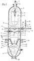
- the fuel (1) over the burner (2) into the combustion chamber (3).
- the fuel is gasified, d. H. it will Generated useful gas.
- the combustion chamber (3) is with ceramic material (4) lined to the Pressure jacket wall (5) of the combustion chamber (3) before too high Protect temperatures. Because of the bad There is thermal conductivity of the ceramic mass an almost adiabatic gasification. This affects favorably on the gasification efficiency.
- the useful gas and the liquid slag leave from Flowing down, the combustion chamber and arrive over the connecting channel (6) at high speed into the quench chamber (7).
- the cooling takes place here by a cooling medium (8), preferably water, which over the nozzle heads (9, 29) of the nozzle blocks (10, 11) in the Useful gas is introduced.
- the nozzle assemblies (10, 11) can be in be arranged at different levels.
- the nozzle sticks are both with a cooling medium connection (12) and with a cold gas connection (13) (for e.g. nitrogen) equipped. Both connections have shut-off valves (14, 15) and flow meter (16, 17) for Ensuring that the Cooling medium in the quench chamber. In case of Using water as the cooling medium becomes nitrogen used as a flushing and inerting medium.
- the nozzle assemblies (10, 11) are on the pressure jacket connector (18) flanged, penetrate the ceramic Lining and are in the cooling position in the quench chamber Quench chamber (7) installed.
- the cone (20) of the quench chamber has one Steel body on one with a coolant acted upon cooling coil (28) is surrounded. Thereby the dimensional stability of the cone (20) compared to Guaranteed hot room and also ensured that the ceramic lining of the conical Steel base body is not damaged.
- the cooling of the cone (20) by means of a cooling coil (28) is unnecessary if a (not shown) double-walled cone with internal cooling is selected.
- the useful gas cooled in the quench chamber (7) leaves the quench chamber via the narrowing cone (20) (7).
- the useful gas carries solid particles and Coolant drops, e.g. B. water droplets, with themselves and is strongly accelerated in the cone (20) and frontally a water bath (21) passed. Because of the high Speed and the relatively large mass of Solid and liquid cooling medium particles succeed not the 180 ° deflection to the Gas outlet connection (23), but they hit the Surface of the water bath (21) on Water bath added and in this way from the Gas flow excreted. That cleaned of solids Gas is deflected by 180 ° and leaves after the Pass through a calming room (22) on the Gas outlet connection (23) the synthesis gas generator.
- Coolant drops e.g. B. water droplets
- the solid particles that have fallen into the water bath e.g. B. slag, are on the solids outlet nozzle (24) deposited.
- the inside of the pressure vessel (5, 31) is in Useful gas contact area by a lining (27) against Corrosion and overtemperature protected.
- Fig. 2 shows the synthesis gas generator with a separate Quench chamber (7).
- the basic principles and working methods are the same as described for FIG. 1. The difference is only that for combustion chamber (3) and Quench chamber (7) two separate pressure vessels (30, 31) exist to form an equipment unit are connected by means of flange (33).
- Fig. 3 shows a longitudinal section through a synthesis gas generator with integrated quench device.
- the quench chamber (7) with a cooling system Mistake.
- the cooling system consists of a cooling basket (41), one gastight welded construction made of cooling pipes and Bridges with a ring distributor (43) and a Ring collector (44) is provided.
- a cooling basket 41
- one gastight welded construction made of cooling pipes and Bridges with a ring distributor (43) and a Ring collector (44) is provided.
- To ring distributor (43) and ring collectors (44) are water supply lines (45) or water drainage lines (46) attached, which are passed through the pressure vessel. In this Range are also the fixed points (47) of the cooling system provided so that the cooling basket (41) a free Has downward expansion possibility.
- Fig. 4 (section A-B of Fig. 3), conveys the situation the nozzle sticks (10, 11) in the quench chamber (7).
Landscapes
- Chemical & Material Sciences (AREA)
- Engineering & Computer Science (AREA)
- Combustion & Propulsion (AREA)
- Oil, Petroleum & Natural Gas (AREA)
- Organic Chemistry (AREA)
- General Chemical & Material Sciences (AREA)
- Chemical Kinetics & Catalysis (AREA)
- Physical Or Chemical Processes And Apparatus (AREA)
- Organic Low-Molecular-Weight Compounds And Preparation Thereof (AREA)
- Hydrogen, Water And Hydrids (AREA)
- Feeding, Discharge, Calcimining, Fusing, And Gas-Generation Devices (AREA)
- Gasification And Melting Of Waste (AREA)
- Pre-Mixing And Non-Premixing Gas Burner (AREA)
- Industrial Gases (AREA)
Applications Claiming Priority (2)
| Application Number | Priority Date | Filing Date | Title |
|---|---|---|---|
| DE19714376 | 1997-04-08 | ||
| DE19714376A DE19714376C1 (de) | 1997-04-08 | 1997-04-08 | Synthesegaserzeuger mit Brenn- und Quenchkammer |
Publications (2)
| Publication Number | Publication Date |
|---|---|
| EP0870818A2 true EP0870818A2 (fr) | 1998-10-14 |
| EP0870818A3 EP0870818A3 (fr) | 1998-11-18 |
Family
ID=7825729
Family Applications (2)
| Application Number | Title | Priority Date | Filing Date |
|---|---|---|---|
| EP98102171A Withdrawn EP0870818A3 (fr) | 1997-04-08 | 1998-02-07 | Gazogène pour gaz de synthèse avec chambre de combustion et de trempe |
| EP98919418A Expired - Lifetime EP0973847B1 (fr) | 1997-04-08 | 1998-04-08 | Generateur de gaz de synthese comprenant des chambres de combustion et de refroidissement rapide |
Family Applications After (1)
| Application Number | Title | Priority Date | Filing Date |
|---|---|---|---|
| EP98919418A Expired - Lifetime EP0973847B1 (fr) | 1997-04-08 | 1998-04-08 | Generateur de gaz de synthese comprenant des chambres de combustion et de refroidissement rapide |
Country Status (10)
| Country | Link |
|---|---|
| US (1) | US5976203A (fr) |
| EP (2) | EP0870818A3 (fr) |
| JP (1) | JPH10316976A (fr) |
| KR (1) | KR19980079750A (fr) |
| AT (1) | ATE204014T1 (fr) |
| AU (1) | AU7228498A (fr) |
| DE (2) | DE19714376C1 (fr) |
| ES (1) | ES2159952T3 (fr) |
| WO (1) | WO1998045388A2 (fr) |
| ZA (1) | ZA982765B (fr) |
Cited By (10)
| Publication number | Priority date | Publication date | Assignee | Title |
|---|---|---|---|---|
| WO2008095980A1 (fr) * | 2007-02-07 | 2008-08-14 | Technische Universität Bergakademie Freiberg | Procédé et dispositif de conversion de gaz bruts issus de la gazéification du charbon |
| WO2008095981A1 (fr) * | 2007-02-07 | 2008-08-14 | Technische Universität Bergakademie Freiberg | Procédé et dispositif de conversion de gaz bruts issus de la gazéification à flux entraîné |
| WO2009033543A1 (fr) * | 2007-09-07 | 2009-03-19 | Choren Industries Gmbh | Procédé et dispositif de traitement de gaz chauds chargés |
| WO2010023306A2 (fr) * | 2008-09-01 | 2010-03-04 | Shell Internationale Research Maatschappij B.V. | Agencement autonettoyant |
| WO2010037602A2 (fr) * | 2008-09-30 | 2010-04-08 | Siemens Aktiengesellschaft | Exploitation de la chaleur sensible du gaz non traité dans la gazéification à flux entraîné |
| DE102009019966A1 (de) | 2009-04-27 | 2010-11-04 | Siemens Aktiengesellschaft | Flugstromvergaser mit Teilquench und erhöhter Partikelabscheidung |
| DE102009030554A1 (de) | 2009-06-25 | 2010-12-30 | Siemens Aktiengesellschaft | Flugstromvergaser für aschebildende Brennstoffe mit Abhitzenutzung |
| CN101250439B (zh) * | 2008-03-28 | 2011-02-09 | 中国船舶重工集团公司第七一一研究所 | 干煤粉气化炉 |
| WO2011089268A3 (fr) * | 2010-01-25 | 2011-12-29 | Shell Internationale Research Maatschappij B.V. | Réacteur et procédé de gazéification |
| WO2012019838A1 (fr) * | 2010-08-10 | 2012-02-16 | Siemens Aktiengesellschaft | Dispositif de prélèvement d'eau de trempe résiduelle contenue dans le fond de l'élément de trempe d'un réacteur de gazéification à flux entraîné |
Families Citing this family (40)
| Publication number | Priority date | Publication date | Assignee | Title |
|---|---|---|---|---|
| US6180237B1 (en) * | 1997-06-13 | 2001-01-30 | Asahi Glass Company Ltd. | Tempered glass |
| DE19930051C2 (de) * | 1999-06-30 | 2001-06-13 | Daimler Chrysler Ag | Vorrichtung und Verfahren zur Durchführung eines Wasser-Quenches |
| US6349658B1 (en) * | 1999-10-28 | 2002-02-26 | Environmental Improvement Systems, Inc. | Auger combustor with fluidized bed |
| DE10004138C2 (de) * | 2000-01-31 | 2002-05-16 | Thermoselect Ag Vaduz | Verfahren und Vorrichtung zur Entsorgung und Verwertung von Abfallgütern |
| FR2848548B1 (fr) * | 2002-12-17 | 2005-12-23 | Air Liquide | Procede de generation d'un melange de synthese co-h2 sous pression par oxydation partielle catalytique en minimisant la formation de suies |
| BRPI0518312A2 (pt) * | 2004-11-22 | 2008-11-11 | Shell Int Research | aparelho para gaseificar um combustÍvel |
| CN1298816C (zh) * | 2005-03-08 | 2007-02-07 | 北京航天动力研究所 | 一种环保型可燃粉体洁净气化装置 |
| US7547423B2 (en) * | 2005-03-16 | 2009-06-16 | Pratt & Whitney Rocketdyne | Compact high efficiency gasifier |
| JP5107903B2 (ja) * | 2005-05-02 | 2012-12-26 | シエル・インターナシヨネイル・リサーチ・マーチヤツピイ・ベー・ウイ | 合成ガスの製造方法及びシステム |
| US7931710B2 (en) * | 2005-07-27 | 2011-04-26 | Babcock & Wilcox Power Generation Group, Inc. | Steam generator to contain and cool synthesis gas |
| AU2007245732B2 (en) * | 2006-05-01 | 2010-07-01 | Air Products And Chemicals, Inc. | Gasification reactor and its use |
| US20080000155A1 (en) * | 2006-05-01 | 2008-01-03 | Van Den Berg Robert E | Gasification system and its use |
| CN101135432B (zh) * | 2006-09-01 | 2013-04-24 | 巴布考克及威尔考克斯公司 | 用于容纳和冷却合成气体的蒸汽发生器 |
| US9051522B2 (en) * | 2006-12-01 | 2015-06-09 | Shell Oil Company | Gasification reactor |
| US7740671B2 (en) * | 2006-12-18 | 2010-06-22 | Pratt & Whitney Rocketdyne, Inc. | Dump cooled gasifier |
| DE102007006990B4 (de) * | 2007-02-07 | 2016-03-10 | Air Liquide Global E&C Solutions Germany Gmbh | Verfahren und Vorrichtung zur Konvertierung von Rohgasen bei der Partialoxidation gasförmiger und flüssiger Kohlenwasserstoffe |
| AU2008294831B2 (en) * | 2007-09-04 | 2012-02-02 | Air Products And Chemicals, Inc. | Quenching vessel |
| ATE554848T1 (de) * | 2007-09-04 | 2012-05-15 | Shell Int Research | Sprühdüsenverteiler und verfahren zum abschrecken eines heissen gases unter verwendung einer derartigen anordnung |
| DE102007044726A1 (de) | 2007-09-18 | 2009-03-19 | Uhde Gmbh | Vergasungsreaktor und Verfahren zur Flugstromvergasung |
| CA2699714C (fr) | 2007-09-18 | 2016-04-19 | Uhde Gmbh | Reacteur de gazeification et procede de gazeification a lit entraine |
| DE102008012734A1 (de) | 2008-03-05 | 2009-09-10 | Uhde Gmbh | Vergasungsreaktor und Verfahren zur Flugstromvergasung |
| US20090130001A1 (en) * | 2007-11-16 | 2009-05-21 | General Electric Company | Methods for fabricating syngas cooler platens and syngas cooler platens |
| US7846226B2 (en) | 2008-02-13 | 2010-12-07 | General Electric Company | Apparatus for cooling and scrubbing a flow of syngas and method of assembling |
| GB0812683D0 (en) * | 2008-07-11 | 2008-08-20 | Chalabi Rifat A | Multi-heat zone gasifier |
| US8475546B2 (en) * | 2008-12-04 | 2013-07-02 | Shell Oil Company | Reactor for preparing syngas |
| US20100139581A1 (en) * | 2008-12-04 | 2010-06-10 | Thomas Ebner | Vessel for cooling syngas |
| US8960651B2 (en) * | 2008-12-04 | 2015-02-24 | Shell Oil Company | Vessel for cooling syngas |
| DE102009034870A1 (de) * | 2009-07-27 | 2011-02-03 | Uhde Gmbh | Vergasungsreaktor zur Herstellung von CO- oder H2-haltigem Rohgas |
| DE102009035052A1 (de) * | 2009-07-28 | 2011-07-28 | Uhde GmbH, 44141 | Vergasungsreaktor mit Doppelwandkühlung |
| DE102010009721B4 (de) * | 2010-03-01 | 2012-01-19 | Thyssenkrupp Uhde Gmbh | Wasserverteilsystem und Verfahren zur Wasserverteilung in einem Vergasungsreaktor zur Durchführung eines schlackebildenden Flugstromverfahrens |
| DE102010033323A1 (de) * | 2010-08-04 | 2012-02-09 | Siemens Aktiengesellschaft | Quenchregime für Vergasungsreaktoren höherer Leistungsklassen |
| KR101134616B1 (ko) * | 2010-08-31 | 2012-04-09 | 한국전력공사 | 가스화 장치의 냉각 장치 |
| CN102329659B (zh) * | 2011-08-24 | 2013-05-15 | 神华集团有限责任公司 | 一种煤气化合成气微孔喷淋激冷室及合成气微孔喷淋激冷方法及其应用 |
| US9504951B2 (en) * | 2011-09-14 | 2016-11-29 | Siemens Aktiengesellschaft | Quenching system for cooling and cleaning dust-conducting crude gasification gas |
| CN102559275B (zh) * | 2012-03-13 | 2013-08-07 | 天津辰创环境工程科技有限责任公司 | 一种水冷气化炉 |
| US9127222B2 (en) * | 2012-07-13 | 2015-09-08 | General Electric Company | System and method for protecting gasifier quench ring |
| KR101357753B1 (ko) * | 2013-06-26 | 2014-02-04 | 국방과학연구소 | 삽입형 인젝터가 구비된 기체혼합기 |
| DE102014201890A1 (de) * | 2014-02-03 | 2015-08-06 | Siemens Aktiengesellschaft | Kühlung und Waschung eines Rohgases aus der Flugstromvergasung |
| JP7134637B2 (ja) * | 2018-02-15 | 2022-09-12 | 三菱重工業株式会社 | ガス化炉設備及びこれを備えたガス化複合発電設備並びにガス化炉設備の製造方法及び生成ガスの排出方法 |
| KR20230067743A (ko) * | 2021-11-08 | 2023-05-17 | 주식회사 선진티에스 | 무함수 석탄을 이용한 가스화기-용광로 복합시스템 및 이를 이용한 방법 |
Family Cites Families (14)
| Publication number | Priority date | Publication date | Assignee | Title |
|---|---|---|---|---|
| DE150313C (fr) * | ||||
| DE2650512B2 (de) * | 1976-11-04 | 1980-03-20 | Gutehoffnungshuette Sterkrade Ag, 4200 Oberhausen | Vorrichtung zum Reinigen von durch chemische Kohlevergasung erzeugtem Synthesegas |
| DD150313A3 (de) * | 1978-09-28 | 1981-08-26 | Friedrich Berger | Vorrichtung zur vergasung asnhehaltiger brennstoffe in der flugwolke |
| US4377394A (en) * | 1979-05-30 | 1983-03-22 | Texaco Development Corporation | Apparatus for the production of cleaned and cooled synthesis gas |
| US4605423A (en) * | 1982-04-12 | 1986-08-12 | Texaco Development Corporation | Apparatus for generating and cooling synthesis gas |
| FR2530796A1 (fr) * | 1982-07-21 | 1984-01-27 | Creusot Loire | Dispositif de conversion et de recuperation thermique |
| CH670501A5 (fr) * | 1986-07-02 | 1989-06-15 | Sulzer Ag | |
| DE3711314A1 (de) * | 1987-04-03 | 1988-10-13 | Babcock Werke Ag | Vorrichtung zum kuehlen eines synthesegases in einem quenchkuehler |
| US4808197A (en) * | 1987-09-24 | 1989-02-28 | Texaco Inc. | Quench ring for a gasifier |
| US4859213A (en) * | 1988-06-20 | 1989-08-22 | Shell Oil Company | Interchangeable quench gas injection ring |
| DD280975B3 (de) * | 1989-03-31 | 1993-03-04 | Noell Dbi Energie Entsorgung | Verfahren und vorrichtung zur kuehlung und reinigung von mit schlacke bzw.staub beladenen druckvergasungsgasen |
| DE4109231C2 (de) * | 1991-03-21 | 1995-01-26 | Noell Dbi Energie Entsorgung | Verfahren zur Verwertung halogenbelasteter kohlenstoffhaltiger Abfallstoffe |
| DE4230124A1 (de) * | 1992-09-09 | 1994-03-10 | Babcock Energie Umwelt | Vorrichtung zur Kühlung von heißen Gasen |
| DE19533908C2 (de) * | 1995-09-13 | 1998-07-23 | Gutehoffnungshuette Man | Abhitzekessel |
-
1997
- 1997-04-08 DE DE19714376A patent/DE19714376C1/de not_active Expired - Fee Related
-
1998
- 1998-02-07 EP EP98102171A patent/EP0870818A3/fr not_active Withdrawn
- 1998-02-20 KR KR1019980005276A patent/KR19980079750A/ko not_active Application Discontinuation
- 1998-04-01 ZA ZA982765A patent/ZA982765B/xx unknown
- 1998-04-07 US US09/056,296 patent/US5976203A/en not_active Expired - Lifetime
- 1998-04-07 JP JP10130942A patent/JPH10316976A/ja active Pending
- 1998-04-08 WO PCT/IB1998/000803 patent/WO1998045388A2/fr active IP Right Grant
- 1998-04-08 AT AT98919418T patent/ATE204014T1/de not_active IP Right Cessation
- 1998-04-08 DE DE69801317T patent/DE69801317T2/de not_active Expired - Fee Related
- 1998-04-08 ES ES98919418T patent/ES2159952T3/es not_active Expired - Lifetime
- 1998-04-08 AU AU72284/98A patent/AU7228498A/en not_active Abandoned
- 1998-04-08 EP EP98919418A patent/EP0973847B1/fr not_active Expired - Lifetime
Non-Patent Citations (1)
| Title |
|---|
| None |
Cited By (15)
| Publication number | Priority date | Publication date | Assignee | Title |
|---|---|---|---|---|
| WO2008095981A1 (fr) * | 2007-02-07 | 2008-08-14 | Technische Universität Bergakademie Freiberg | Procédé et dispositif de conversion de gaz bruts issus de la gazéification à flux entraîné |
| WO2008095980A1 (fr) * | 2007-02-07 | 2008-08-14 | Technische Universität Bergakademie Freiberg | Procédé et dispositif de conversion de gaz bruts issus de la gazéification du charbon |
| WO2009033543A1 (fr) * | 2007-09-07 | 2009-03-19 | Choren Industries Gmbh | Procédé et dispositif de traitement de gaz chauds chargés |
| US8770555B2 (en) | 2007-09-07 | 2014-07-08 | Ccg Energy Technology Company Ltd. | Method and device for treating charged hot gas |
| CN101250439B (zh) * | 2008-03-28 | 2011-02-09 | 中国船舶重工集团公司第七一一研究所 | 干煤粉气化炉 |
| WO2010023306A2 (fr) * | 2008-09-01 | 2010-03-04 | Shell Internationale Research Maatschappij B.V. | Agencement autonettoyant |
| WO2010023306A3 (fr) * | 2008-09-01 | 2010-07-29 | Shell Internationale Research Maatschappij B.V. | Agencement autonettoyant |
| WO2010037602A3 (fr) * | 2008-09-30 | 2010-09-10 | Siemens Aktiengesellschaft | Exploitation de la chaleur sensible du gaz non traité dans la gazéification à flux entraîné |
| WO2010037602A2 (fr) * | 2008-09-30 | 2010-04-08 | Siemens Aktiengesellschaft | Exploitation de la chaleur sensible du gaz non traité dans la gazéification à flux entraîné |
| DE102009019966A1 (de) | 2009-04-27 | 2010-11-04 | Siemens Aktiengesellschaft | Flugstromvergaser mit Teilquench und erhöhter Partikelabscheidung |
| DE102009030554A1 (de) | 2009-06-25 | 2010-12-30 | Siemens Aktiengesellschaft | Flugstromvergaser für aschebildende Brennstoffe mit Abhitzenutzung |
| DE102009030554B4 (de) * | 2009-06-25 | 2011-10-27 | Siemens Aktiengesellschaft | Flugstromvergaser für aschebildende Brennstoffe mit Abhitzenutzung |
| WO2011089268A3 (fr) * | 2010-01-25 | 2011-12-29 | Shell Internationale Research Maatschappij B.V. | Réacteur et procédé de gazéification |
| US9234147B2 (en) | 2010-01-25 | 2016-01-12 | Shell Oil Company | Gasification reactor and process |
| WO2012019838A1 (fr) * | 2010-08-10 | 2012-02-16 | Siemens Aktiengesellschaft | Dispositif de prélèvement d'eau de trempe résiduelle contenue dans le fond de l'élément de trempe d'un réacteur de gazéification à flux entraîné |
Also Published As
| Publication number | Publication date |
|---|---|
| EP0870818A3 (fr) | 1998-11-18 |
| WO1998045388A3 (fr) | 1999-01-07 |
| JPH10316976A (ja) | 1998-12-02 |
| DE19714376C1 (de) | 1999-01-21 |
| DE69801317T2 (de) | 2001-11-22 |
| DE69801317D1 (de) | 2001-09-13 |
| ZA982765B (en) | 1998-10-08 |
| WO1998045388A2 (fr) | 1998-10-15 |
| ATE204014T1 (de) | 2001-08-15 |
| US5976203A (en) | 1999-11-02 |
| AU7228498A (en) | 1998-10-30 |
| EP0973847B1 (fr) | 2001-08-08 |
| KR19980079750A (ko) | 1998-11-25 |
| EP0973847A2 (fr) | 2000-01-26 |
| ES2159952T3 (es) | 2001-10-16 |
Similar Documents
| Publication | Publication Date | Title |
|---|---|---|
| EP0870818A2 (fr) | Gazogène pour gaz de synthèse avec chambre de combustion et de trempe | |
| EP0616023B1 (fr) | Appareil de gazéification pour la gazéification sous pression de combustibles finement divisés | |
| DE102006031816B4 (de) | Verfahren und Vorrichtung zur Kühlung von heißen Gasen und verflüssigter Schlacke bei der Flugstromvergasung | |
| DE102006059149B4 (de) | Flugstromreaktor zur Vergasung fester und flüssiger Energieträger | |
| DE112009000287B4 (de) | Vorrichtung zum Kühlen und Waschen einer Strömung von Synthesegas und Verfahren zum Zusammenbauen | |
| EP0351563B1 (fr) | Appareillage pour la production de gaz à partir de solides carbonifères finement divisés | |
| DE102011088628B4 (de) | Verfahren und Vorrichtung zur Flugstromvergasung fester Brennstoffe unter Druck | |
| EP0459023B1 (fr) | Appareil pour gazéifier des matériaux carbonifères | |
| DE2940257A1 (de) | Strahlungskessel | |
| DE102007042543A1 (de) | Verfahren und Vorrichtung zur Behandlung von beladenem Heißgas | |
| EP0616022B1 (fr) | Procédé pour la gazéification sous pression de combustibles finement divisés | |
| DE3601786C2 (de) | Einrichtung zur Abkühlung des aus einem unter erhöhtem Druck betriebenen Vergasungsreaktor austretenden heißen Produktionsgases | |
| DE102014104232B4 (de) | Brennstaub-Brenner und Flugstromvergaser für die Herstellung von Synthesegas | |
| DE4001739A1 (de) | Verfahren und vorrichtung zur kuehlung und reinigung von mit schlacke bzw. staub beladenen druckvergasungsgasen | |
| DE102011107726B4 (de) | Vorrichtung und Verfahren zum Einleiten von nachwachsenden Brennstoffen in den Bereich der Strahlungskesselwand von Vergasungsreaktoren | |
| EP2459683B1 (fr) | Réacteur de gazéification pour la fabrication de gaz brut à teneur en co ou h2 | |
| DE2935752C2 (de) | Vorrichtung zur Vergasung aschehaltiger Brennstoffe | |
| DE202014101214U1 (de) | Brenner für einen Flugstromvergaser | |
| EP0662506A1 (fr) | Procédé et appareillage pour refroidir du gaz brut d'oxydation partielle | |
| EP0716138B1 (fr) | Installation pour la gazéiffication sous pression de combustibles finement divisés afine de produire un gaz | |
| DE202015106170U1 (de) | Flugstromreaktor zur Erzeugung von Synthesegas | |
| DE4307462C2 (de) | Einrichtung für die Vergasung feinkörniger bis staubförmiger Brennstoffe und Verfahren zu deren Betrieb | |
| DE102015119696A1 (de) | Flugstromreaktor zur Erzeugung von Synthesegas | |
| DE102016211869A1 (de) | Kombinierter Freiraumquench für einen Flugstromvergasungsreaktor großer Leistung mit Quench- und Waschstufe | |
| DE102007027601A1 (de) | Herstellung und Kühlung von gasförmigen Kohlevergasungsprodukten |
Legal Events
| Date | Code | Title | Description |
|---|---|---|---|
| PUAI | Public reference made under article 153(3) epc to a published international application that has entered the european phase |
Free format text: ORIGINAL CODE: 0009012 |
|
| PUAL | Search report despatched |
Free format text: ORIGINAL CODE: 0009013 |
|
| AK | Designated contracting states |
Kind code of ref document: A2 Designated state(s): AT DE ES FR GB IT NL |
|
| AX | Request for extension of the european patent |
Free format text: AL;LT;LV;MK;RO;SI |
|
| AK | Designated contracting states |
Kind code of ref document: A3 Designated state(s): AT BE CH DE DK ES FI FR GB GR IE IT LI LU MC NL PT SE |
|
| AX | Request for extension of the european patent |
Free format text: AL;LT;LV;MK;RO;SI |
|
| 17P | Request for examination filed |
Effective date: 19990308 |
|
| STAA | Information on the status of an ep patent application or granted ep patent |
Free format text: STATUS: THE APPLICATION HAS BEEN WITHDRAWN |
|
| AKX | Designation fees paid |
Free format text: AT DE ES FR GB IT NL |
|
| 18W | Application withdrawn |
Withdrawal date: 19990630 |