EP0870539A2 - Dispositif pour polymérisation en phase gazeuse - Google Patents
Dispositif pour polymérisation en phase gazeuse Download PDFInfo
- Publication number
- EP0870539A2 EP0870539A2 EP98106447A EP98106447A EP0870539A2 EP 0870539 A2 EP0870539 A2 EP 0870539A2 EP 98106447 A EP98106447 A EP 98106447A EP 98106447 A EP98106447 A EP 98106447A EP 0870539 A2 EP0870539 A2 EP 0870539A2
- Authority
- EP
- European Patent Office
- Prior art keywords
- gas
- phase
- discharge pipe
- phase polymerization
- polymer
- Prior art date
- Legal status (The legal status is an assumption and is not a legal conclusion. Google has not performed a legal analysis and makes no representation as to the accuracy of the status listed.)
- Withdrawn
Links
Images
Classifications
-
- B—PERFORMING OPERATIONS; TRANSPORTING
- B01—PHYSICAL OR CHEMICAL PROCESSES OR APPARATUS IN GENERAL
- B01J—CHEMICAL OR PHYSICAL PROCESSES, e.g. CATALYSIS OR COLLOID CHEMISTRY; THEIR RELEVANT APPARATUS
- B01J8/00—Chemical or physical processes in general, conducted in the presence of fluids and solid particles; Apparatus for such processes
- B01J8/0015—Feeding of the particles in the reactor; Evacuation of the particles out of the reactor
-
- B—PERFORMING OPERATIONS; TRANSPORTING
- B01—PHYSICAL OR CHEMICAL PROCESSES OR APPARATUS IN GENERAL
- B01J—CHEMICAL OR PHYSICAL PROCESSES, e.g. CATALYSIS OR COLLOID CHEMISTRY; THEIR RELEVANT APPARATUS
- B01J8/00—Chemical or physical processes in general, conducted in the presence of fluids and solid particles; Apparatus for such processes
- B01J8/18—Chemical or physical processes in general, conducted in the presence of fluids and solid particles; Apparatus for such processes with fluidised particles
- B01J8/1818—Feeding of the fluidising gas
- B01J8/1827—Feeding of the fluidising gas the fluidising gas being a reactant
Definitions
- the present invention relates to a gas-phase polymerization apparatus, and more specifically to a gas-phase polymerization apparatus in which a monomer and/or comonomer in a gas-phase as a starting material of polymer is reacted in the presence of solid polymerization catalyst and other gas-phase necessary for the polymerization to yield a polymer in the form of powder (hereinafter referred as "powder polymer").
- a monomer or a gas containing monomer is introduced into the lower part of gas-phase polymerization vessel through a gas introduction conduit by means of compressor or blower (so far as not to be given especially, "gas” means generally a monomer or a gas containing monomer).
- the gas introduced into the gas-phase polymerization vessel is then distributed homogeneously in the gas-phase polymerization vessel by a gas-distributing plate disposed in the lower part of the gas-phase polymerization vessel and has a number of perforations.
- the homogeneously distributed gas goes up in the gas-phase polymerization vessel.
- the polymerization takes place while powders such as powder polymer, which has already been a polymer through the ascending gas stream, are being fluidized.
- the fluidized particles then may form a constant fluidizing layer and the thickness of the layer may be controlled, for example, by the fluidizaion of gas.
- the monomer is contacting with the catalyst particles (solid polymerization catalyst) to be polymerized.
- a gas discharge pipe is connected to the gas-phase polymerization vessel at the upper part of the vessel, the gas being exhausted from the part.
- the gas introduction pipe and gas discharge pipe may form a gas-phase circulation system (for example, a circular conduit) for circulating the gas to the vessel.
- a gas-phase circulation system for example, a circular conduit
- the gas-phase circulation system is provided with a gas circulator such as a blower and the like.
- the gas circulator is a device for flowing a gas through the gas-phase circulation system to the gas-phase polymerization vessel.
- the gas circulator is also a device for feeding the gas that is in an unreacted condition in the gas-phase polymerization vessel and drawn out therefrom, and a gas that is newly fed, if necessary, to the vessel.
- the gas that is fed into the gas-phase polymerization vessel by a gas circulator may be polymerized as mentioned above to yield a powder polymer.
- the gas that does not take part in the polymerization in the gas-phase polymerization vessel is exhausted through the gas discharge pipe from the gas-phase polymerization vessel and then fed again through the gas introduction pipe to the gas-phase polymerization vessel to be subjected to the polymerization with repeating the production of powder polymer.
- a monomer and comonomer as the starting material of polymer as well as a solid polymerization catalyst etc. are naturally supplied to the gas-phase circulation system, thereby the amount of these components consumed in the polymerization may be compensated.
- the gas containing a monomer and/or comonomer as well as the circulation gas, which are supplied to the gas-phase circulation system may be those being capable of forming a fluidizing layer and may contain partially a liquid phase.
- a readily volatile and a coagulative medium such as propane, butane or the like may be contained though such medium is inert to the polymerization.
- a sedimentation equipment connected to the polymer discharge pipe is provided to the gas-phase polymerization vessel.
- Such a equipment is called as tank, dram and the like, however, it will be referred to generally as “sedimentation tank” hereinafter.
- the sedimentation tank means a place for transporting, from the gas-phase polymerization vessel, the powder polymer that has already been formed by the polymerization in the gas-phase polymerization vessel.
- the polymer discharge pipe is used for transporting the powder polymer from the gas-phase polymerization vessel to the sedimentation tank.
- the transportation is accompanied with a gas, which has been not used for the polymerization and may contain the unreacted monomer, the polymerization catalyst and the like. Therefore, other than the powder polymer, a gas containing the unreacted monomer, the polymerization catalyst, etc. may enter into the sedimentation tank.
- gases are collected in the upper part of the sedimentation tank and drawn out from the sedimentation tank through a gas discharge pipe equipped to the upper part of the sedimentation tank.
- the discharged gas is then returned through the gas discharge pipe to the gas-phase polymerization vessel to be reused for the polymerization.
- the gas discharge pipe is connected to the upper space of the vessel.
- the gas to be returned from the sedimentation tank through the gas discharge pipe to the gas-phase polymerization vessel is accompanied with a small amount of powder polymer.
- the small amount of powder polymer is occasionally adhered to the end of the gas discharge pipe facing to the inside of the vessel. Then, since the powder polymer grows there to form a large mass, there is a worriment that the end opening of the gas discharge pipe would be blocked. When the mass would be fallen off from the end opening of the gas discharge pipe, the fallen mass of powder polymer will subside in the gas-phase polymerization vessel to block soon the fine holes of the gas-distributing plate. As a result, there is a worriment that blocking of the gas-distributing plate would be occurred.
- the present invention has been made to solve the above-mentioned conventional problems, and therefore an object of the present invention is to provide a gas-phase polymerization apparatus in which forming of the mass of powder polymer in the gas discharge pipe can be prevented.
- the present inventors have found that the growth of powder polymer at the end of the gas discharge pipe facing to the inside of the gas-phase polymerization vessel is caused from (1) the low gas flow rate in the upper space in the vessel being connected to the gas discharge pipe and (2) the presence of the site in the gas-phase circulation system where the gas flow rate is higher than that in the upper space of the gas-phase polymerization vessel.
- the present inventors have invented a gas-phase polymerization apparatus in which the growth of powder polymer in the gas discharge pipe may be prevented very easily.
- the gas-phase polymerization apparatus is comprised of: a gas-phase polymerization vessel in which the polymerization is carried out in the gas-phase in the presence of solid polymerization catalyst to form a powder polymer; a gas-phase circulation system in which the unreacted monomer being not subjected to the polymerization in the gas-phase polymerization vessel and other gas-phases are discharged from the gas-phase polymerization vessel and fed again to the gas-phase polymerization vessel for the circulation thereof; a polymer discharge pipe for discharging the powder polymer formed by the polymerization in the gas-phase polymerization vessel therefrom; a sedimentation equipment for sedimentating the powder polymer that is discharged from the polymer discharge pipe being connected to the polymer discharge pipe; and a gas discharge pipe that may connect the sedimentation equipment to the lower pressure portion in the gas-phase circulation system than the pressure in the sedimentation equipment, for drawing out at least a part of the gas-phase that may enter into the sedimentation equipment through the polymer discharge pipe together
- the circulation system according to the present invention is comprised of: a gas exhaust port of the gas-phase polymerization vessel; a refrigeration equipment; a blower or compressor; a gas introduction port of the gas-phase polymerization vessel; and pipings directly or indirectly connecting them.
- An equipment other than those as mentioned above, for example, a drain pot or the like may be provided between the gas exhaust port and the gas introduction port.
- the arrangement and the number of the devices may be selected arbitrarily, if necessary.
- the gas-phase polymerization vessel of the present invention intends to discharge the gas-phase, which may enter together with the powder polymer through the polymer discharge pipe from the vessel into the sedimentation tank, from said sedimentation tank.
- the sedimentation tank is connected through a gas discharge pipe to the lower pressure portion of the gas-phase circulation system than the pressure in the sedimentation tank.
- the gas-phase in the sedimentation tank may be introduced through the gas discharge pipe into the gas-phase circulation system.
- the gas discharge pipe may be connected anywhere in the gas-phase circulation system, preferably it is connected to the site having, for example, a linear velocity of equal to or more than 5 m/sec of the circulation gas in terms of the cross-section of the pipe, and more preferably equal to or more than 10 m/sec.
- the upper limit of the linear velocity of circulation gas is not critical but preferably, from the view point of preventing the increase of pressure loss and the vibration of piping, it is in general equal to or less than 100 m/sec, more preferably equal to or less than 50 m/sec.
- both a refrigeration equipment to remove the heat of reaction in the polymerization and a gas-phase circulation equipment to circulate the gas-phase in the gas-phase circulation system are provided in the system, in which the refrigeration equipment is disposed at the gas exhaust side of the vessel and that the gas discharge pipe is connected to the site between the refrigeration and the gas-phase circulation equipment in the circulation system.
- the gas exhaust port of the gas-phase polymerization vessel, a heat remover, a blower or compressor and a gas introduction pipe of the gas-phase polymerization vessel are arranged in this series in the gas-phase circulation system, it is preferred to connect the gas discharge pipe of the sedimentation tank to the place which is between the heat remover and the blower or compressor.
- the gas flow rate in the gas discharge pipe is higher than the case in which the gas discharge pipe is connected in a common manner to the upper space of the gas-phase polymerization vessel. Accordingly, the mass of polymer is not formed in the gas discharge pipe, so that it becomes unnecessary to clean the gas discharge pipe and the gas-distributing plate, which must be cleaned conventionally. Therefore, it is not necessary to stop the operation of the gas-phase polymerization vessel, resulting in no reduction of the productivity.
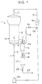
- a gas-phase polymerization apparatus 1 has a gas-phase polymerization vessel 3 having a gas-distributing plate 2 in the inside.
- the gas-phase polymerization vessel 3 is a vessel in which a monomer in the gas-phase as a starting material of polymer is polymerized in the presence of solid polymerization catalyst, if necessary, with a comonomer to form a powder polymer.
- the gas-phase polymerization vessel 3 has a gas introduction pipe 5 in the lower portion thereof and a gas discharge pipe 7 in the upper portion thereof, and are connected to each other.
- the gas introduction pipe 5 and the gas discharge pipe 7 are included in the gas-phase circulation system, through which unreacted monomer having been not subjected to the polymerization in the gas-phase polymerization vessel 3 is recirculated to the gas-phase polymerization vessel 3.
- a fluid bed is formed in the gas-phase polymerization vessel 3 by a gas containing the unreacted monomer and a monomer being fed newly to the gas-phase polymerization apparatus 1. It should be noted that the monomer and other gases necessary for the polymerization may be fed at a suitable portion in the gas-phase circulation system 9 (for example, as shown by numeral (1) in Fig. 1).
- the gas-phase circulation system 9 includes, other than the gas introduction pipe 5 and the gas discharge pipe 7, a heat remover 9a as a cooling equipment and a gas blower (or compressor) 9b as a gas-phase circulation equipment, which are arranged between the gas introduction pipe 5 and the gas discharge pipe 7.
- the heat of reaction generated by the polymerization is released outside the apparatus by the heat remove 9a.
- the gas is circulated repeatedly in the gas-phase circulation system 9 by means of a circulating gas blower 9b.
- the direction of gas circulation is shown by white arrows.
- the solid polymerization catalyst is fed, for example, at the portion as shown by the numeral (1) in Fig. 1 and a comonomer being fed, if necessary, for example, at the portion shown by numeral (1) or (2) in Fig. 1.
- a sedimentation tank 13 as a sedimentating equipment is connected to the lower portion of the gas-phase polymerization vessel 3 through a polymer discharge pipe 12 having a ball valve 11.
- the polymer discharge pipe 12 may discharge the powder polymer formed by the polymerization in the gas-phase polymerization vessel 3 to the outside of the gas-phase polymerization vessel 3.
- the sedimentation tank 13 precipitates therein the powder polymer discharged from the polymer discharge pipe 12 and, when the ball valve 11 is opened, the powder polymer and the gas which are from the gas-phase polymerization vessel 3 through the polymer discharge pipe 12 enter into the sedimentation tank 13.
- a portion along the direction of gas circulation and between the heat remover 9a and the circulation gas blower 9b in the route of gas-phase circulation system 9 is the portion of the lower pressure than the pressure in the sedimentation tank 13. More specifically, the other end 15b of the gas discharge pipe 15 is connected to the portion directly just after the heat remover 9a in the circulation system 9.
- a vent valve 15c is provided in the middle of gas discharge pipe 15. The vent valve 15c is a valve for controlling the volume of gas flowing in the gas discharge pipe 15 and in general opened.
- a transportation tank 17 is connected to the lower end of the sedimentation tank 13 through a connecting pipe 19 having a ball valve 18.
- the transportation tank 17 is the final tank for transporting the powder polymer accumulated in the sedimentation tank 13 to the other treatment equipment (not shown).
- the shape of transportation tank 17 may be the same as or different from the sedimentation tank 13.
- the ball valve 18 may introduce the powder polymer in the sedimentation tank 13 to the transportation tank 17 and the lower portion of the transportation tank 17 is connected to a transporting pipe 23 through a discharge valve 25, which is always opened.
- the gas entering and accompanying with the powder polymer from the gas-phase polymerization vessel 3 through the polymer discharge pipe 12 into the sedimentation tank 13 is introduced through the gas discharge pipe 15 into the portion between the heat remover 9a and the circulation gas blower 9b in the gas-phase circulation system 9.
- the gas flow rate in the gas discharge pipe 15 is higher than the case in which the gas discharge pipe 15 is connected in a common manner to the upper space of the gas-phase polymerization vessel 3. Accordingly, the mass of powder polymer is not formed in the gas discharge pipe 15.
- the gas discharge pipe 15 and the gas-distributing plate 2 may be not blocked with the mass of powder polymer, so that it becomes unnecessary to clean the gas discharge pipe and the gas-distributing plate, which must be cleaned conventionally. Therefore, it is not necessary to stop the operation of the gas-phase polymerization apparatus 1 resulting in no reduction of the productivity.
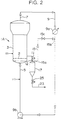
- the gas-phase polymerization apparatus 1A as shown in Fig. 2, which is a modification example of the gas-phase polymerization apparatus 1, is different from the apparatus 1 in that the apparatus 1A has no sedimentation tank 13 as well as no connecting pipe 19 having the ball valve 18 and accompanying with the tank 13; and that the members down the transportation tank 17 are connected directly to the polymer discharge pipe 12 having the ball valve 11.
- the gas-phase polymerization apparatus 1A has no sedimentation tank 13 and no connecting pipe 19, so that the powder polymer is discharged always continuously from the gas-phase polymerization vessel 3 to the transportation tank 17 and transported continuously to the other treatment equipment as mentioned above through the conveying pipe 23 having the discharge valve 25 being opened all the time.
- the transportation tank 17 is connected to the portion of lower pressure than the pressure in the transportation tank 17 of the gas-phase circulation system 9 through the route of polymerization vessel 3 - polymer discharge pipe 12 - transporation tank 17 - gas discharge pipe 15. Insert pipes are disposed in the tank 17 to form the powder surface. Otherwise, the level of the powder surface is determined by a radiation liquid surface meter etc. and its level is adjusted by the ball valve 11. At this time, the gas separated in the transportation tank 17 may be discharged therefrom and introduced into the circulation system 9. As a result, the gas discharge pipe 15 and the gas-distributing plate 2 may be not blocked, so that it may be not required to clean the pipe and the plate as in the gas-phase polymerization apparatus 1.
Applications Claiming Priority (2)
| Application Number | Priority Date | Filing Date | Title |
|---|---|---|---|
| JP09216297A JP3710247B2 (ja) | 1997-04-10 | 1997-04-10 | 気相重合装置 |
| JP92162/97 | 1997-04-10 |
Publications (2)
| Publication Number | Publication Date |
|---|---|
| EP0870539A2 true EP0870539A2 (fr) | 1998-10-14 |
| EP0870539A3 EP0870539A3 (fr) | 1998-10-21 |
Family
ID=14046740
Family Applications (1)
| Application Number | Title | Priority Date | Filing Date |
|---|---|---|---|
| EP98106447A Withdrawn EP0870539A3 (fr) | 1997-04-10 | 1998-04-08 | Dispositif pour polymérisation en phase gazeuse |
Country Status (5)
| Country | Link |
|---|---|
| EP (1) | EP0870539A3 (fr) |
| JP (1) | JP3710247B2 (fr) |
| KR (1) | KR19980081250A (fr) |
| CN (1) | CN1203120A (fr) |
| CA (1) | CA2234510A1 (fr) |
Cited By (6)
| Publication number | Priority date | Publication date | Assignee | Title |
|---|---|---|---|---|
| WO2000029452A1 (fr) * | 1998-11-12 | 2000-05-25 | Borealis Technology Oy | Procede et dispositif de decharge des reacteurs de polymerisation |
| US6914104B2 (en) | 2002-04-19 | 2005-07-05 | Sumitomo Chemical Company, Limited | Process for polymerization of α-olefin |
| WO2007102942A1 (fr) * | 2006-03-08 | 2007-09-13 | Univation Technologies, Llc | Procede et appareil de polymerisation |
| WO2012175469A1 (fr) | 2011-06-21 | 2012-12-27 | Basell Polyolefine Gmbh | Procédé et appareil pour décharger un polymère d'un réacteur en phase gazeuse |
| CN102863561A (zh) * | 2011-07-08 | 2013-01-09 | 中国石油化工股份有限公司 | 一种气相聚合反应装置及烯烃聚合方法 |
| EP2594333A1 (fr) * | 2011-11-21 | 2013-05-22 | Borealis AG | Procédé de récupération de polymère et appareil associé |
Citations (4)
| Publication number | Priority date | Publication date | Assignee | Title |
|---|---|---|---|---|
| EP0381364A1 (fr) * | 1989-01-31 | 1990-08-08 | BP Chemicals Limited | Procédé et appareil de polymérisation d'oléfines en phase gazeuse dans un réacteur à lit fluidisé |
| US5453471A (en) * | 1994-08-02 | 1995-09-26 | Union Carbide Chemicals & Plastics Technology Corporation | Gas phase polymerization process |
| EP0728771A1 (fr) * | 1995-02-24 | 1996-08-28 | BP Chemicals Limited | Appareillage et procédé de polymérisation d'oléfine en phase gazeuse |
| WO1997008211A1 (fr) * | 1995-08-31 | 1997-03-06 | The Goodyear Tire & Rubber Company | Synthese en phase vapeur de polymeres caoutchouteux |
-
1997
- 1997-04-10 JP JP09216297A patent/JP3710247B2/ja not_active Expired - Lifetime
-
1998
- 1998-04-08 EP EP98106447A patent/EP0870539A3/fr not_active Withdrawn
- 1998-04-09 KR KR1019980012649A patent/KR19980081250A/ko not_active Application Discontinuation
- 1998-04-09 CN CN98108893A patent/CN1203120A/zh active Pending
- 1998-04-09 CA CA002234510A patent/CA2234510A1/fr not_active Abandoned
Patent Citations (5)
| Publication number | Priority date | Publication date | Assignee | Title |
|---|---|---|---|---|
| EP0381364A1 (fr) * | 1989-01-31 | 1990-08-08 | BP Chemicals Limited | Procédé et appareil de polymérisation d'oléfines en phase gazeuse dans un réacteur à lit fluidisé |
| US5453471A (en) * | 1994-08-02 | 1995-09-26 | Union Carbide Chemicals & Plastics Technology Corporation | Gas phase polymerization process |
| US5453471B1 (en) * | 1994-08-02 | 1999-02-09 | Carbide Chemicals & Plastics T | Gas phase polymerization process |
| EP0728771A1 (fr) * | 1995-02-24 | 1996-08-28 | BP Chemicals Limited | Appareillage et procédé de polymérisation d'oléfine en phase gazeuse |
| WO1997008211A1 (fr) * | 1995-08-31 | 1997-03-06 | The Goodyear Tire & Rubber Company | Synthese en phase vapeur de polymeres caoutchouteux |
Cited By (14)
| Publication number | Priority date | Publication date | Assignee | Title |
|---|---|---|---|---|
| WO2000029452A1 (fr) * | 1998-11-12 | 2000-05-25 | Borealis Technology Oy | Procede et dispositif de decharge des reacteurs de polymerisation |
| AU755948B2 (en) * | 1998-11-12 | 2003-01-02 | Borealis Technology Oy | Method and apparatus for discharging polymerization reactors |
| US7655192B2 (en) | 1998-11-12 | 2010-02-02 | Borealis Technology Oy | Method and apparatus for discharging polymerization reactors |
| US7812102B2 (en) | 1998-11-12 | 2010-10-12 | Borealis Technology Oy | Method and apparatus for discharging polymerization reactors |
| US6914104B2 (en) | 2002-04-19 | 2005-07-05 | Sumitomo Chemical Company, Limited | Process for polymerization of α-olefin |
| WO2007102942A1 (fr) * | 2006-03-08 | 2007-09-13 | Univation Technologies, Llc | Procede et appareil de polymerisation |
| WO2012175469A1 (fr) | 2011-06-21 | 2012-12-27 | Basell Polyolefine Gmbh | Procédé et appareil pour décharger un polymère d'un réacteur en phase gazeuse |
| CN102863561A (zh) * | 2011-07-08 | 2013-01-09 | 中国石油化工股份有限公司 | 一种气相聚合反应装置及烯烃聚合方法 |
| CN102863561B (zh) * | 2011-07-08 | 2014-08-13 | 中国石油化工股份有限公司 | 一种气相聚合反应装置及烯烃聚合方法 |
| EP2594333A1 (fr) * | 2011-11-21 | 2013-05-22 | Borealis AG | Procédé de récupération de polymère et appareil associé |
| WO2013075808A1 (fr) * | 2011-11-21 | 2013-05-30 | Borealis Ag | Procédé pour la récupération de polymère et appareil correspondant |
| CN103747863A (zh) * | 2011-11-21 | 2014-04-23 | 博里利斯股份公司 | 回收聚合物的方法及其装置 |
| US8916660B2 (en) | 2011-11-21 | 2014-12-23 | Borealis Ag | Method for recovering polymer and apparatus therefor |
| CN103747863B (zh) * | 2011-11-21 | 2016-09-07 | 博里利斯股份公司 | 回收聚合物的方法及其装置 |
Also Published As
| Publication number | Publication date |
|---|---|
| JPH10279611A (ja) | 1998-10-20 |
| EP0870539A3 (fr) | 1998-10-21 |
| CA2234510A1 (fr) | 1998-10-10 |
| JP3710247B2 (ja) | 2005-10-26 |
| CN1203120A (zh) | 1998-12-30 |
| KR19980081250A (ko) | 1998-11-25 |
Similar Documents
| Publication | Publication Date | Title |
|---|---|---|
| FI111953B (fi) | Menetelmä ja laite polymerointireaktoreiden tyhjentämiseksi | |
| KR100388507B1 (ko) | 기상올레핀중합용장치및방법 | |
| KR100532831B1 (ko) | 기상 중합 방법 및 장치 | |
| EP0648697B1 (fr) | Méthode et appareil pour transporter des particules | |
| EP0870539A2 (fr) | Dispositif pour polymérisation en phase gazeuse | |
| US6953553B2 (en) | Process and apparatus for separating diluent from polymer solids | |
| KR20040091644A (ko) | 루프 반응기를 사용하는 연속적인 슬러리 중합 방법 | |
| EP0830892B1 (fr) | Appareil et procédé pour la polymérisation d'oléfine en phase gazeuse | |
| US7714083B2 (en) | Recycle of hydrocarbon gases from the product tanks to a reactor through the use of ejectors | |
| JP5055816B2 (ja) | ポリオレフィンパウダーの移送装置及び方法 | |
| JPH0373565B2 (fr) | ||
| CN102639207B (zh) | 流体分离系统和方法 | |
| JP2000053707A (ja) | 気相重合装置 | |
| JP3373673B2 (ja) | 粉粒体移送方法及び装置 | |
| CZ130794A3 (en) | Method of exhausting dust fro a reactor and apparatus for making the same | |
| JP4760173B2 (ja) | オレフィン連続重合装置、ポリマー粉粒体の移送方法、およびオレフィン重合方法 | |
| JP5321131B2 (ja) | オレフィン重合体の製造方法 | |
| US20240009646A1 (en) | Polyolefin production apparatus and polyolefin production method | |
| CN116490525A (zh) | 聚烯烃排放工艺和设备 | |
| MXPA00011306A (en) | Continuous slurry polymerization volatile removal | |
| CN117881470A (zh) | 用于处理聚合物颗粒的容器及其操作方法 | |
| JP2006117712A (ja) | ポリオレフィンの製造方法 | |
| JP2005068207A (ja) | ポリオレフィン粉粒体の移送方法 | |
| MX2008008276A (en) | Gas-phase process and apparatus for the polymerization of olefins |
Legal Events
| Date | Code | Title | Description |
|---|---|---|---|
| PUAI | Public reference made under article 153(3) epc to a published international application that has entered the european phase |
Free format text: ORIGINAL CODE: 0009012 |
|
| PUAL | Search report despatched |
Free format text: ORIGINAL CODE: 0009013 |
|
| AK | Designated contracting states |
Kind code of ref document: A2 Designated state(s): DE FR GB IT NL |
|
| AX | Request for extension of the european patent |
Free format text: AL;LT;LV;MK;RO;SI |
|
| AK | Designated contracting states |
Kind code of ref document: A3 Designated state(s): AT BE CH CY DE DK ES FI FR GB GR IE IT LI LU MC NL PT SE |
|
| AX | Request for extension of the european patent |
Free format text: AL;LT;LV;MK;RO;SI |
|
| 17P | Request for examination filed |
Effective date: 19990218 |
|
| AKX | Designation fees paid |
Free format text: DE FR GB IT NL |
|
| STAA | Information on the status of an ep patent application or granted ep patent |
Free format text: STATUS: THE APPLICATION HAS BEEN WITHDRAWN |
|
| 18W | Application withdrawn |
Withdrawal date: 19991014 |