EP0870100B1 - Appareil de combustion sans flamme et procede - Google Patents
Appareil de combustion sans flamme et procede Download PDFInfo
- Publication number
- EP0870100B1 EP0870100B1 EP96944607A EP96944607A EP0870100B1 EP 0870100 B1 EP0870100 B1 EP 0870100B1 EP 96944607 A EP96944607 A EP 96944607A EP 96944607 A EP96944607 A EP 96944607A EP 0870100 B1 EP0870100 B1 EP 0870100B1
- Authority
- EP
- European Patent Office
- Prior art keywords
- fuel
- combustion chamber
- oxidant
- temperature
- combustor
- Prior art date
- Legal status (The legal status is an assumption and is not a legal conclusion. Google has not performed a legal analysis and makes no representation as to the accuracy of the status listed.)
- Expired - Lifetime
Links
Images
Classifications
-
- F—MECHANICAL ENGINEERING; LIGHTING; HEATING; WEAPONS; BLASTING
- F23—COMBUSTION APPARATUS; COMBUSTION PROCESSES
- F23C—METHODS OR APPARATUS FOR COMBUSTION USING FLUID FUEL OR SOLID FUEL SUSPENDED IN A CARRIER GAS OR AIR
- F23C13/00—Apparatus in which combustion takes place in the presence of catalytic material
- F23C13/02—Apparatus in which combustion takes place in the presence of catalytic material characterised by arrangements for starting the operation, e.g. for heating the catalytic material to operating temperature
-
- E—FIXED CONSTRUCTIONS
- E21—EARTH DRILLING; MINING
- E21B—EARTH DRILLING, e.g. DEEP DRILLING; OBTAINING OIL, GAS, WATER, SOLUBLE OR MELTABLE MATERIALS OR A SLURRY OF MINERALS FROM WELLS
- E21B36/00—Heating, cooling, insulating arrangements for boreholes or wells, e.g. for use in permafrost zones
- E21B36/02—Heating, cooling, insulating arrangements for boreholes or wells, e.g. for use in permafrost zones using burners
-
- E—FIXED CONSTRUCTIONS
- E21—EARTH DRILLING; MINING
- E21B—EARTH DRILLING, e.g. DEEP DRILLING; OBTAINING OIL, GAS, WATER, SOLUBLE OR MELTABLE MATERIALS OR A SLURRY OF MINERALS FROM WELLS
- E21B43/00—Methods or apparatus for obtaining oil, gas, water, soluble or meltable materials or a slurry of minerals from wells
- E21B43/16—Enhanced recovery methods for obtaining hydrocarbons
- E21B43/24—Enhanced recovery methods for obtaining hydrocarbons using heat, e.g. steam injection
- E21B43/243—Combustion in situ
-
- F—MECHANICAL ENGINEERING; LIGHTING; HEATING; WEAPONS; BLASTING
- F23—COMBUSTION APPARATUS; COMBUSTION PROCESSES
- F23C—METHODS OR APPARATUS FOR COMBUSTION USING FLUID FUEL OR SOLID FUEL SUSPENDED IN A CARRIER GAS OR AIR
- F23C2900/00—Special features of, or arrangements for combustion apparatus using fluid fuels or solid fuels suspended in air; Combustion processes therefor
- F23C2900/99001—Cold flame combustion or flameless oxidation processes
-
- Y—GENERAL TAGGING OF NEW TECHNOLOGICAL DEVELOPMENTS; GENERAL TAGGING OF CROSS-SECTIONAL TECHNOLOGIES SPANNING OVER SEVERAL SECTIONS OF THE IPC; TECHNICAL SUBJECTS COVERED BY FORMER USPC CROSS-REFERENCE ART COLLECTIONS [XRACs] AND DIGESTS
- Y02—TECHNOLOGIES OR APPLICATIONS FOR MITIGATION OR ADAPTATION AGAINST CLIMATE CHANGE
- Y02E—REDUCTION OF GREENHOUSE GAS [GHG] EMISSIONS, RELATED TO ENERGY GENERATION, TRANSMISSION OR DISTRIBUTION
- Y02E20/00—Combustion technologies with mitigation potential
- Y02E20/34—Indirect CO2mitigation, i.e. by acting on non CO2directly related matters of the process, e.g. pre-heating or heat recovery
Definitions
- This invention relates to a combustor apparatus and method.
- U.S. Patent Nos. 4,640,352 and 4,886,118 disclose conductive heating of subterranean formations of low permeability that contain oil to recover oil therefrom.
- Low permeability formations include diatomites, lipid coals, tar sands, and oil shales. Formations of low permeability are not amiable to enhanced oil recovery methods such as steam, carbon dioxide, or fire flooding. Flooding materials tend to penetrate formations that have low permeabilities preferentially through fractures. The injected materials bypass most of the formation hydrocarbons. In contrast, conductive heating does not require fluid transport into the formation. Oil within the formation is therefore not bypassed as in a flooding process.
- U.S. Patent Nos. 3,113,623 and 3,181,613 disclose gas fired heat injection burners for heating subterranean formations. These burners utilize porous materials to hold a flame and thereby spreading the flame out over an extended length. Radiant heat transfer from a flame to the casing is avoided by providing the porous medium to hold the flame. But for combustion to take place in the porous medium, the fuel gas and the combustion air must be premixed. If the premixed fuel gas and combustion air were at a temperature above the autoignition temperature of the mixture, they would react upon being premixed instead of within the porous medium.
- the formations utilized as examples of these inventions are only up to about 15 m thick and below only about 4.5 m of overburden. The fuel gas and the combustion air are therefore relatively cool when they reach the burner. The burner would not function as it was intended if the formation being heated were significantly deeper.
- U.S. Patent No. 5,255,742 discloses a flameless combustor useful for heating subterranean formations that utilizes preheated fuel gas and/or combustion air wherein the fuel gas is combined with the combustion air in increments that are sufficiently small that flames are avoided. Creation of NO x is almost eliminated, and cost of the heaters can be significantly reduced because of less expensive materials of construction. Preheating the fuel gas in accordance with the teachings of this prior art reference results in coke formation unless CO 2 , H 2 , steam, or some other coke suppressant is added to the fuel gas. Further, start-up of this known heater is a time consuming process because it must operate at temperatures above the autoignition temperature of the fuel gas mixture. Start-up requires long periods of very low flow-rate operation before temperatures would be sufficiently high for normal operation.
- Catalytic combustors are also known.
- U.S. Patent No. 3,928,961 discloses a catalytically-supported thermal combustion apparatus wherein formation of NO x is eliminated by combustion at temperatures above auto-ignition temperatures of the fuel, but less than those temperatures at which result in substantial formation of oxides of nitrogen.
- a flameless combustor and ignition method in accordance with the preamble of claims 1 and 12 is known from US Patent 5,404,952.
- coiled electrical resistor wires are suspended within the combustion chamber at a distance away from the orifices, which may retard and complicate ignition.
- each of the orifices are separated by an interval distance wherein the oxidant can pass through the combustion chamber and mix with fuel passing through the orifices from the fuel volume as the oxidant passes from the inlet end to the combustion product outlet; and a catalytic surface is located within the axial combustion chamber, the catalytic surface effective to reduce the autoignition temperature of a mixture of fuel and oxidant from a non-catalyzed autoignition temperature to a catalyzed autoignition temperature.
- the catalytic surface comprises an outer surface of the fuel conduit and/or an inner surface of the combustion chamber. It is also preferred that the catalytic surface comprises palladium.
- the combustor is located within an underground wellbore and the fuel conduit is a tubular suspended from a wellhead; electrical power is applied at the wellhead; the fuel conduit is of a lesser thickness in the vicinity of the orifices than above the orifices; and the fuel conduit is grounded from a point below at least one orifice.
- the invention further relates to a method to ignite a flameless combustor.
- the method according to the invention is defined in claim 12.
- the method according to the invention further comprises the step of passing an amount of electricity through the fuel conduit sufficient to cause the fuel conduit, for at least a portion of the conduit in the vicinity of at least one orifice, to heat to a temperature of at least 260 °C.
- the method according to the invention further comprises the step of providing a catalytic surface within the combustion chamber, the catalytic surface effective to reduce the temperature at which the fuel and oxidant react in the vicinity of the catalytic surface.
- Suitable fuels for use during the start-up phase of the method according to the present invention are hydrogen and a hydrogen and carbon monoxide mixture, which fuels have a low ignition temperature.
- the flameless combustion method and combustor of the present invention result in minimal production of nitrous oxides. Other measures to remove or prevent the formation of nitrous oxides are therefore not required.
- a flameless combustor that can be utilized, with improvement according to the present invention is disclosed in U.S. Patent No. 5,255,742, the disclosure of which is incorporated herein by reference.
- the improvements of the present invention include three improvements related to the start-up of such a combustor.
- the three improvements may be used individually, but are preferably used in combination with at least two utilized.
- the three improvements of the present invention include: use of the fuel gas conduit as a resistance heater to provide heat for start-up; use of a catalytic surface within the combustion chamber to lower temperatures at which oxidation of the fuel will occur; and use of oxidants other than air, or along with air, to lower autoignition temperatures during start-up.
- An important feature of the flameless combustor of the present invention is that heat is removed along the axis of the combustion chamber so that a temperature is maintained that is significantly below what an adiabatic combustion temperature would be. This almost eliminates formation of NO x s, and also significantly reduces metallurgical requirements resulting in a relatively inexpensive combustor.
- flameless combustion is accomplished by preheating combustion air and fuel gas sufficiently that when the two streams are combined the temperature of the mixture exceeds the autoignition temperature of the mixture, but to a temperature less than that which would result in the oxidation upon mixing being limited by the rate of mixing.
- Preheating of the streams to a temperature between about 815 °C and about 1260 °C and then mixing the fuel gas into the combustion air in relatively small increments will result in flameless combustion.
- the increments in which the fuel gas is mixed with the combustion gas stream preferably result in about a 10 to 110 °C temperature rise in the combustion gas stream due to the combustion of the fuel.
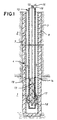
- a heat injection well and combustor capable of carrying out the present invention are shown.
- a formation to be heated, 1, is below an overburden, 2.
- a wellbore, 3, extends through the overburden and to a position in or near the bottom of the formation to be heated.
- a vertical well is shown, but the wellbore could be deviated or horizontal.
- Horizontal heat injector wells may be provided in formations that fracture horizontally to recover hydrocarbons by a parallel drive process. Shallow oil shale formations are examples of such formations.
- Horizontal heaters may also effectively be used in thin beds to limit heat loss to overburden and base rock.
- the wellbore is cased with a casing, 4.
- the lower portion of the wellbore may be cemented with a cement, 7, having characteristics suitable for withstanding elevated temperatures and transferring heat.
- a cement which is a good thermal insulator, 8, is preferred for the upper portion of the wellbore to prevent heat loss from the system.
- An oxidant conduit, 10, extends from the wellhead (not shown) to the lower portion of the wellbore.
- a fuel conduit, 12, also extends from the wellhead to the bottom of the wellbore.
- the fuel conduit defines a fuel volume within the fuel conduit. The fuel volume is in communication with a fuel supply, and is in communication with a combustion chamber surrounding the fuel conduit through a plurality of orifices.
- High temperature cements suitable for cementing casing and conduits within the high temperature portions of the wellbore are available. Examples are disclosed in U.S. Patent Nos. 3,507,332 and 3,180,748. Alumina contents above about 50 percent by weight based on cements slurry solids are preferred.
- the heater In shallow formations, it may be advantageous to hammer-drill the heater directly into the formation.
- cementing of the heater in the formation is not required, but an upper portion of the heater may be cemented to prevent fluid loss to the surface.
- Choice of a diameter of the casing, 4, in the embodiment of FIG. 1 is a trade off between the expense of the casing, and the rate at which heat may be transferred into the formation.
- the casing due to the metallurgy required, is generally the most expensive component of the injection well.
- the heat that can be transferred into the formation increases significantly with increasing casing diameter.
- a casing of between about 10 and about 20 cm in internal diameter will typically provide an optimum trade-off between initial cost and heat transfer.
- the fuel gas conduit contains a plurality of orifices, 13, (eight shown) along the length of the conduit within the formation to be heated.
- the orifices are separated by an interval distance that is sufficient to allow both significant reaction of the oxidant and fuel between orifices, and removal of heat from the heater along the length of the combustion chamber between the orifices.
- the orifices 13 provide communication between the volume defined by the fuel conduit 12 and the axial combustion chamber.
- a plurality of orifices provide for distribution of heat release within the formation to be heated. Staging release of fuel into the oxidant/combustion product stream results in staged generation of heat, and with uniform transfer of heat from the wellbore as in the embodiment of FIG. 1, temperatures within the wellbore are well below adiabatic combustion temperatures. Avoiding high temperatures significantly reduces metallurgical requirements, and thus cost of the facility. Additionally, temperatures well below adiabatic combustion temperatures avoids creation of NO x s.
- the orifices are sized to accomplish a nearly even temperature distribution within the casing.
- a nearly even temperature profile within the casing results in more uniform heat distribution within the formation to be heated.
- a nearly uniform heat distribution within the formation will result in more efficient utilization of heat in a conductive heating hydrocarbon recovery process.
- a more even temperature profile will also result in lower maximum temperatures for the same heat release. Because the materials of construction of the burner and well system dictate the maximum temperatures, even temperature profiles will increase the heat release possible for the same materials of construction.
- the number of orifices is limited only by size of orifices which are to be used. If more orifices are used, they must generally be of a smaller size. Smaller orifices will plug more easily than larger orifices. The number of orifices is a trade-off between evenness of the temperature profile and the possibility of plugging.
- the number, size, and spacing of the orifices along with the heat removal from the combustion chamber are preferably such that the maximum temperatures within the combustor are less than about 1100 °C. This results in long service lives for commercially available materials.
- heat be removed from the combustion chamber between fuel orifices.
- heat is transferred to the formation around the wellbore.
- the heater of the present invention could also be used in other applications, such as steam generation and chemical industry or refinery process heaters.
- air and/or another oxidant could be staged into fuel by providing orifices in the combustion air conduit instead of the fuel conduit.
- Fuel and oxidant transported to bottom of the wellbore combine and react within the wellbore volume surrounding the conduits, 14, forming combustion products.
- This volume is the axial combustion chamber of the present invention.
- the combustion products travel up the wellbore and out an exhaust vent at the wellhead.
- the combustion products may be treated to remove pollutants, and energy recovery from the combustion products by an expander turbine or heat exchanger may also be desirable.
- An electrical lead 15 can be connected with a clamp 16 or other connection to the fuel line 12 near the wellhead below an electrically insulating coupling to supply electrical energy for initial heating and start-up of the combustor.
- Electrical ground can be provided near the bottom of the borehole with one or more electrically conducting centralizers around the fuel conduit 17 and around the oxidant conduit 18.
- Centralizers on the fuel conduit above the electrically grounding centralizers are electrically insulating centralizers. Wall thickness of the fuel conduits are preferably decreased in the vicinity of the orifices so that application of electrical energy to the fuel gas conduit results in negligible resistance heating above the orifices, and significant heating below the orifices.
- Sufficient heat is preferably applied to result in fuel exiting the orifices into a flowing oxidant (or air) stream being is at or above the autoignition temperature of the fuel-oxidant mixture as the fuel mixes with the oxidant.
- the mixture of fuel and oxidant is above the autoignition temperature of the mixture at these start-up conditions.
- the fuel would ignite when it passes through the orifices and mixe with oxidant between orifices.
- Autoignition temperature of the fuel-oxidant mixture is preferably lowered by provision of a catalytic surface 19 in the vicinity of the orifices.
- This catalytic surface is preferably provided on the inside surface of the oxidant conduit 10.
- the fuel conduit could be provided with such a surface, or a tubular or catalyst containing surface could be separately placed within the oxidant conduit.
- Other catalytic surfaces could be provided, for example in the combustion product annulus outside of the oxidant conduit. This additional catalytic surface could ensure that complete combustion occurred within the wellbore.
- the catalytic surface can also significantly increase the temperature range within which the combustor can operate by decreasing the temperature at which oxidation of the fuel occurs.
- Start up of the flameless combustor of the present invention can be further enhanced by provision of supplemental oxidants during the start-up phase, and/or by use of a fuel that has a lower autoignition temperature such as, for example, hydrogen.
- Preferred oxidants include supplemental oxygen and nitrous oxide.
- Hydrogen could be provided along with a natural gas stream, and could be provided as shift gas, with carbon monoxide present and/or carbon dioxide present. Presence of carbon dioxide would not be preferably, but may be tolerable and removal of some carbon dioxide may not be economically justifiable.
- Acceptable catalyst materials include noble metals, semi-precious metals, and transition metal oxides. Generally, known oxidation catalysts are useful in the present invention. Mixtures of such metals or metal oxides could also be useful.
- Start-up oxidants and/or fuels are preferably only used until the combustor has been heated to a temperature sufficient to enable operation with methane (natural gas) as fuel and air as the oxidant (i.e., the combustor has heated to a temperature above the autoignition temperature of methane in air).
- the preheating of fuel gases such as methane to obtain flameless combustion could result in significant generation of carbon within the fuel conduit unless a carbon formation suppressant is included in the fuel stream.
- the carbon formation suppressant may be carbon dioxide, steam, hydrogen or mixtures thereof. Carbon dioxide and steam are preferred due to the generally higher cost of hydrogen.
- Flameless combustion generally occurs when a reaction between an oxidant stream and a fuel is not limited by mixing and the mixed stream is at a temperature higher than the autoignition temperature of the mixed stream. This is accomplished by avoiding high temperatures at the point of mixing and by mixing relatively small increments of fuel into the oxidant containing stream. The existence of flame is evidenced by an illuminate interface between unburned fuel and the combustion products.
- the fuel and the oxidant are preferably heated to a temperature of between about 815 °C and about 1260 °C prior to mixing.
- the fuel is preferably mixed with the oxidant stream in relatively small increments to enable more rapid mixing. For example, enough fuel may be added in an increment to enable combustion to raise the temperature of the stream by about 28 to about 56 °C.
- the fuel conduit as a resistance heater to provide initial heat for start up of the flameless combustor of the present invention is a significant improvement because the fuel conduit is present anyway, will generally be made of an electrically conductive material, and being a relatively thick metal, would be expected to be a reliable heater. Thickness of the fuel conduit can be varied to result in release of heat at preselected segments of the length of the fuel conduit. For example, in a well heat injector application, it may be desirable to electrically heat the lowermost portion of the wellbore in order to ignite the mixed gas stream at the highest concentration of fuel, and to burn the fuel before exhaust gasses are passed back up through the wellbore. Electrical energy can be connected to the fuel conduit at the wellhead, and the fuel conduit supported by an insulating hanger, and kept centralized within the air supply conduit with insulating centralizers. The fuel conduit is then grounded below the segment which is to be used as a heater.
- Catalytic metals such as palladium or platinum can be coated, preferably by brush electroplating, onto a surface within the combustion chamber to enhance oxidation of the fuel at lower temperatures.
- Such catalytic surface has been found to be extremely effective in promoting oxidation of methane in air at temperatures as low as 260 °C. This reaction rapidly occurs on the catalyst surface, and generally, gasses in the boundary layer adjacent to the catalytic surface quickly become fully reacted.
- An advantage of having a significant catalytic surface within the combustion chamber is that the temperature range within which the flameless combustor can operate can be significantly increased.
- a thermal reactor was used to establish temperatures at which oxidation reactions would occur with various combinations of fuels, oxidants and catalyst surfaces.
- the reactor was a 2.54 cm stainless steel pipe wrapped with an electrical resistance heating coil, and covered with insulation.
- a thermocouple for temperature control was placed underneath the insulation adjacent to the outer surface of the pipe. Thermocouples were also provided inside the pipe at the inlet, at the middle, and at the outlet. Test ribbons of noble metals or stainless steel strips with noble metal coatings were hung in the pipe to test catalytic activity. Air preheated to a temperature somewhat below the desired temperature of the test was injected into the electrically heated test section of the pipe.
- a 3.048 m long test combustor was used to test the results of the one inch reactor in a distributed combustor application.
- a 2.54 cm outer diameter fuel gas line was provided within a 5.08 cm internal diameter combustion line.
- the fuel injection line provided a conduit for fuel to a fuel injection port located near an inlet end of the combustion line.
- the combustion line was placed within an insulated pipe, and thermocouples were placed along the fuel supply line. Two different combustion lines were utilized.
- One combustion line was fabricated from a strip of "HAYNES 120" alloy. The strip was electro brush plated on one side with palladium to an average thickness of 0.000254 cm.
- the strip was then break formed, swedged and welded in to a 3.048 m long pipe with the palladium coating on the inside surface.
- the other combustion line was a standard 7.62 cm pipe of "HAYNES 120" alloy.
- a "MAXON” burner was used to supply combustion gases to the 3.048 m long combustion pipe, and varying amounts of air and/or other additives are mixed with the exhaust from the "MAXON” burner in a mixing section between the burner and the combustion line.
- three electric heaters, each with its own controller, were placed outside and along the length of the combustion line.
Landscapes
- Engineering & Computer Science (AREA)
- Geology (AREA)
- Life Sciences & Earth Sciences (AREA)
- Mining & Mineral Resources (AREA)
- Geochemistry & Mineralogy (AREA)
- Fluid Mechanics (AREA)
- Environmental & Geological Engineering (AREA)
- General Life Sciences & Earth Sciences (AREA)
- Physics & Mathematics (AREA)
- Chemical & Material Sciences (AREA)
- Combustion & Propulsion (AREA)
- Chemical Kinetics & Catalysis (AREA)
- Mechanical Engineering (AREA)
- General Engineering & Computer Science (AREA)
- Physical Or Chemical Processes And Apparatus (AREA)
- Gas Burners (AREA)
- Fluidized-Bed Combustion And Resonant Combustion (AREA)
- Combustion Of Fluid Fuel (AREA)
Claims (16)
- Dispositif de combustion sans flammes, comportant :caractérisé en ce que le moyen de chauffage électrique comprend une alimentation (15) en énergie électrique efficace pour faire passer un courant électrique dans le conduit de combustible (12) en quantité efficace pour chauffer le conduit de combustible (12) au voisinage d'au moins un orifice (13), à une température située au-dessus d'une température à laquelle le combustible s'allume lorsque le combustible traverse les orifices.une chambre axiale de combustion (14) en communication avec une entrée d'oxydant à une extrémité et en communication avec une sortie de produits de combustion à l'autre extrémité;un conduit de combustible (12) situé à l'intérieur de la chambre axiale de combustion (14), le conduit de combustible (12) définissant un volume de combustible, le volume de combustible étant en communication avec une alimentation en combustible et en communication avec la chambre de combustion (14) par une pluralité d'orifices (13) située le long du conduit de combustible (12), le conduit de combustible (12) comportant un matériau électriquement conducteur; etun moyen de chauffage électrique pour l'allumage du mélange d'oxydant et de combustible à l'intérieur de la chambre de combustion axiale;
- Dispositif de combustion selon la revendication 1, dans lequel le dispositif de combustion est placé dans un puits foré (3).
- Dispositif de combustion selon la revendication 2, dans lequel le conduit de combustible (12) est un tube suspendu à une tête de puits; de l'énergie électrique est appliquée sur la tête de puits, le conduit de combustible est d'une épaisseur plus faible au voisinage des orifices (13) qu'au-dessus des orifices; et le conduit de combustible est raccordé à la terre en un point situé en dessous d'au moins un orifice (13).
- Dispositif de combustion sans flammes selon la revendication 1, dans lequel :les orifices (13) sont séparés les uns des autres par une distance d'intervalle sur laquelle l'oxydant peut traverser la chambre de combustion (14) et se mélanger avec le combustible traversant les orifices (13) en provenance du volume de combustible, pendant que l'oxydant passe de l'extrémité d'entrée jusqu'à la sortie de produits de combustion; etune surface catalytique (19) située à l'intérieur de la chambre de combustion axiale (14), la surface catalytique (19) étant efficace pour réduire la température d'auto-allumage d'un mélange de combustible et d'oxydant, depuis une température d'auto-allumage non catalysé jusqu'à une température d'auto-allumage catalysé.
- Dispositif de combustion selon la revendication 4, dans lequel la surface catalytique (19) comprend une surface extérieure du conduit de combustible (12).
- Dispositif de combustion selon la revendication 4, dans lequel la surface catalytique (19) comprend une surface intérieure de la chambre de combustion (14).
- Dispositif de combustion selon la revendication 4, dans lequel la chambre de combustion (14) est définie par une surface intérieure d'un tube (10) placé dans un puits foré.
- Dispositif de combustion selon la revendication 4, comportant en outre un moyen pour extraire de la chaleur de l'intervalle de la chambre de combustion (14) situé entre au moins deux orifices (13), le moyen pour extraire la chaleur étant capable de d'extraire une quantité de chaleur qui entraíne que la température à l'intérieur de la chambre de combustion (14) est, en conditions de régime permanent, supérieure à la température d'auto-allumage du combustible dans l'air, mais inférieure à environ 1100° C.
- Dispositif de combustion selon la revendication 8, dans lequel le moyen pour extraire la chaleur d'un intervalle de la chambre de combustion situé entre au moins deux des orifices (13) comprend la formation (1) dans laquelle la chaleur en provenance de la chambre de combustion (14) peut être transférée par convection et conduction à travers un espace annulaire entourant la chambre de combustion (14).
- Dispositif de combustion selon la revendication 4, dans lequel la surface catalytique (19) comprend du palladium.
- Dispositif de combustion selon la revendication 4, dans lequel le conduit de combustible (12) est un tube suspendu à une tête de puits, et le dispositif de combustion est situé dans un puits foré (3) et comprend en outre un moyen (15) pour appliquer de l'énergie électrique sur le conduit de combustible en tête du puits; et le conduit de combustible est d'une épaisseur plus faible au voisinage des orifices qu'au-dessus des orifices, et le conduit de combustible est raccordé à la terre en un point situé en dessous d'au moins un orifice.
- Procédé pour allumer un dispositif de combustion sans flammes, lequel procédé comprend les étapes consistant à :caractérisé en ce que la réaction a lieu lorsque le combustible se combine avec l'oxydant et en ce que l'oxydant est choisi dans le groupe comprenant l'oxyde nitreux et l'oxygène supplémentaire, et en ce que le procédé comporte en outre les étapes consistant à:fournir une chambre de combustion axiale (14) en communication avec une entrée d'oxydant à une extrémité et en communication avec une sortie de produits de combustion à l'autre extrémité;fournir un conduit de combustible (12) à l'intérieur de la chambre de combustion (14), le conduit de combustible (12) définissant un volume de carburant, le volume de carburant étant en communication avec une alimentation de combustible et en communication avec la chambre de combustion (14) par une pluralité d'orifices (13) situés le long du conduit de combustible (12);faire passer un oxydant dans la chambre de combustion (14);faire passer un écoulement de combustible dans le volume de combustible; etchauffer l'écoulement de combustible, l'écoulement d'oxydant ou les deux écoulements de combustible et d'oxydant à une température qui entraíne la réaction de l'oxydant et du combustible;continuer à amener l'oxydant dans la chambre de combustion (14) et le combustible dans le conduit de combustible jusqu'à ce que la température à l'intérieur de la chambre de combustion (14) dépasse une température d'auto-allumage du combustible dans l'air; etremplacer l'oxydant par de l'air lorsque la température à l'intérieur de la chambre de combustion (14) devient supérieure à la température d'auto-allumage du combustible dans l'air.
- Procédé selon la revendication 12, comprenant en outre l'étape consistant à faire passer dans le conduit de combustible (12) une quantité d'électricité suffisante pour provoquer l'échauffement du conduit de combustible (12) à une température d'au moins 260° C sur au moins une partie de conduit (12) située à proximité d'au moins un orifice (13).
- Procédé selon la revendication 12, comprenant en outre l'étape consistant à prévoir une surface catalytique (19) à l'intérieur de la chambre de combustion (14), la surface catalytique (19) étant efficace pour diminuer la température à laquelle le combustible et l'oxydant réagissent au voisinage de la surface catalytique (19).
- Procédé selon la revendication 12, dans lequel le combustible est l'hydrogène.
- Procédé selon la revendication 12, dans lequel le combustible comprend de l'hydrogène et du monoxyde de carbone.
Applications Claiming Priority (3)
| Application Number | Priority Date | Filing Date | Title |
|---|---|---|---|
| US934595P | 1995-12-27 | 1995-12-27 | |
| US9345P | 1995-12-27 | ||
| PCT/EP1996/005753 WO1997024509A1 (fr) | 1995-12-27 | 1996-12-17 | Appareil de combustion sans flamme |
Publications (2)
| Publication Number | Publication Date |
|---|---|
| EP0870100A1 EP0870100A1 (fr) | 1998-10-14 |
| EP0870100B1 true EP0870100B1 (fr) | 2000-03-29 |
Family
ID=21737075
Family Applications (1)
| Application Number | Title | Priority Date | Filing Date |
|---|---|---|---|
| EP96944607A Expired - Lifetime EP0870100B1 (fr) | 1995-12-27 | 1996-12-17 | Appareil de combustion sans flamme et procede |
Country Status (21)
| Country | Link |
|---|---|
| US (3) | US5899269A (fr) |
| EP (1) | EP0870100B1 (fr) |
| JP (1) | JP3747066B2 (fr) |
| KR (1) | KR100445853B1 (fr) |
| CN (1) | CN1079885C (fr) |
| AT (1) | ATE191254T1 (fr) |
| AU (1) | AU696743B2 (fr) |
| BR (1) | BR9612363A (fr) |
| CA (1) | CA2240411C (fr) |
| DE (1) | DE69607485T2 (fr) |
| DK (1) | DK0870100T3 (fr) |
| EA (1) | EA000249B1 (fr) |
| EG (1) | EG21060A (fr) |
| ES (1) | ES2145513T3 (fr) |
| GR (1) | GR3033618T3 (fr) |
| IL (1) | IL124806A (fr) |
| JO (1) | JO1948B1 (fr) |
| MA (1) | MA24040A1 (fr) |
| PT (1) | PT870100E (fr) |
| TR (2) | TR199900452T2 (fr) |
| WO (1) | WO1997024509A1 (fr) |
Families Citing this family (217)
| Publication number | Priority date | Publication date | Assignee | Title |
|---|---|---|---|---|
| TR199900452T2 (xx) * | 1995-12-27 | 1999-07-21 | Shell Internationale Research Maatschappij B.V. | Alevsiz yak�c�. |
| US5985222A (en) * | 1996-11-01 | 1999-11-16 | Noxtech, Inc. | Apparatus and method for reducing NOx from exhaust gases produced by industrial processes |
| US6588504B2 (en) | 2000-04-24 | 2003-07-08 | Shell Oil Company | In situ thermal processing of a coal formation to produce nitrogen and/or sulfur containing formation fluids |
| US6698515B2 (en) | 2000-04-24 | 2004-03-02 | Shell Oil Company | In situ thermal processing of a coal formation using a relatively slow heating rate |
| US6688387B1 (en) | 2000-04-24 | 2004-02-10 | Shell Oil Company | In situ thermal processing of a hydrocarbon containing formation to produce a hydrocarbon condensate |
| US6715546B2 (en) | 2000-04-24 | 2004-04-06 | Shell Oil Company | In situ production of synthesis gas from a hydrocarbon containing formation through a heat source wellbore |
| US6715548B2 (en) | 2000-04-24 | 2004-04-06 | Shell Oil Company | In situ thermal processing of a hydrocarbon containing formation to produce nitrogen containing formation fluids |
| US7011154B2 (en) * | 2000-04-24 | 2006-03-14 | Shell Oil Company | In situ recovery from a kerogen and liquid hydrocarbon containing formation |
| US6880633B2 (en) * | 2001-04-24 | 2005-04-19 | Shell Oil Company | In situ thermal processing of an oil shale formation to produce a desired product |
| US7104319B2 (en) * | 2001-10-24 | 2006-09-12 | Shell Oil Company | In situ thermal processing of a heavy oil diatomite formation |
| US7090013B2 (en) * | 2001-10-24 | 2006-08-15 | Shell Oil Company | In situ thermal processing of a hydrocarbon containing formation to produce heated fluids |
| US6932155B2 (en) * | 2001-10-24 | 2005-08-23 | Shell Oil Company | In situ thermal processing of a hydrocarbon containing formation via backproducing through a heater well |
| US7165615B2 (en) * | 2001-10-24 | 2007-01-23 | Shell Oil Company | In situ recovery from a hydrocarbon containing formation using conductor-in-conduit heat sources with an electrically conductive material in the overburden |
| US6684948B1 (en) | 2002-01-15 | 2004-02-03 | Marshall T. Savage | Apparatus and method for heating subterranean formations using fuel cells |
| US7182132B2 (en) * | 2002-01-15 | 2007-02-27 | Independant Energy Partners, Inc. | Linearly scalable geothermic fuel cells |
| US8200072B2 (en) | 2002-10-24 | 2012-06-12 | Shell Oil Company | Temperature limited heaters for heating subsurface formations or wellbores |
| US6796789B1 (en) | 2003-01-14 | 2004-09-28 | Petro-Chem Development Co. Inc. | Method to facilitate flameless combustion absent catalyst or high temperature oxident |
| US7121342B2 (en) | 2003-04-24 | 2006-10-17 | Shell Oil Company | Thermal processes for subsurface formations |
| US7631691B2 (en) * | 2003-06-24 | 2009-12-15 | Exxonmobil Upstream Research Company | Methods of treating a subterranean formation to convert organic matter into producible hydrocarbons |
| WO2005038347A2 (fr) * | 2003-10-10 | 2005-04-28 | Bacon David W | Appareil d'allumage de milieux combustibles |
| US20060289536A1 (en) | 2004-04-23 | 2006-12-28 | Vinegar Harold J | Subsurface electrical heaters using nitride insulation |
| US7168949B2 (en) * | 2004-06-10 | 2007-01-30 | Georgia Tech Research Center | Stagnation point reverse flow combustor for a combustion system |
| US7425127B2 (en) * | 2004-06-10 | 2008-09-16 | Georgia Tech Research Corporation | Stagnation point reverse flow combustor |
| US7293606B2 (en) * | 2005-03-09 | 2007-11-13 | 391854 Alberta Limited | Heat exchanging apparatus |
| US8016589B2 (en) * | 2005-03-10 | 2011-09-13 | Shell Oil Company | Method of starting up a direct heating system for the flameless combustion of fuel and direct heating of a process fluid |
| JP2008532747A (ja) * | 2005-03-10 | 2008-08-21 | シエル・インターナシヨネイル・リサーチ・マーチヤツピイ・ベー・ウイ | 燃料の燃焼とプロセス流体の加熱のための伝熱システム及びその使用方法 |
| US8027571B2 (en) | 2005-04-22 | 2011-09-27 | Shell Oil Company | In situ conversion process systems utilizing wellbores in at least two regions of a formation |
| US7966822B2 (en) * | 2005-06-30 | 2011-06-28 | General Electric Company | Reverse-flow gas turbine combustion system |
| WO2007050469A1 (fr) | 2005-10-24 | 2007-05-03 | Shell Internationale Research Maatschappij B.V. | Radiateur limité en température avec un conduit sensiblement isolé de manière électrique de la formation |
| GB2442639B (en) * | 2005-10-26 | 2008-09-17 | Schlumberger Holdings | Downhole sampling apparatus and method for using same |
| RU2411350C2 (ru) * | 2005-12-21 | 2011-02-10 | Ветко Грэй Скандинавиа Ас | Способ и устройство для выработки электроэнергии под водой |
| US20070269755A2 (en) * | 2006-01-05 | 2007-11-22 | Petro-Chem Development Co., Inc. | Systems, apparatus and method for flameless combustion absent catalyst or high temperature oxidants |
| US7591306B2 (en) * | 2006-02-27 | 2009-09-22 | Geosierra Llc | Enhanced hydrocarbon recovery by steam injection of oil sand formations |
| US20070199697A1 (en) * | 2006-02-27 | 2007-08-30 | Grant Hocking | Enhanced hydrocarbon recovery by steam injection of oil sand formations |
| US7604054B2 (en) * | 2006-02-27 | 2009-10-20 | Geosierra Llc | Enhanced hydrocarbon recovery by convective heating of oil sand formations |
| US20070199695A1 (en) * | 2006-02-27 | 2007-08-30 | Grant Hocking | Hydraulic Fracture Initiation and Propagation Control in Unconsolidated and Weakly Cemented Sediments |
| US20070199700A1 (en) * | 2006-02-27 | 2007-08-30 | Grant Hocking | Enhanced hydrocarbon recovery by in situ combustion of oil sand formations |
| US7748458B2 (en) * | 2006-02-27 | 2010-07-06 | Geosierra Llc | Initiation and propagation control of vertical hydraulic fractures in unconsolidated and weakly cemented sediments |
| US20070199712A1 (en) * | 2006-02-27 | 2007-08-30 | Grant Hocking | Enhanced hydrocarbon recovery by steam injection of oil sand formations |
| US20070199710A1 (en) * | 2006-02-27 | 2007-08-30 | Grant Hocking | Enhanced hydrocarbon recovery by convective heating of oil sand formations |
| US8151874B2 (en) | 2006-02-27 | 2012-04-10 | Halliburton Energy Services, Inc. | Thermal recovery of shallow bitumen through increased permeability inclusions |
| US20070199705A1 (en) * | 2006-02-27 | 2007-08-30 | Grant Hocking | Enhanced hydrocarbon recovery by vaporizing solvents in oil sand formations |
| US7404441B2 (en) * | 2006-02-27 | 2008-07-29 | Geosierra, Llc | Hydraulic feature initiation and propagation control in unconsolidated and weakly cemented sediments |
| US7520325B2 (en) | 2006-02-27 | 2009-04-21 | Geosierra Llc | Enhanced hydrocarbon recovery by in situ combustion of oil sand formations |
| US20070199711A1 (en) * | 2006-02-27 | 2007-08-30 | Grant Hocking | Enhanced hydrocarbon recovery by vaporizing solvents in oil sand formations |
| US7866395B2 (en) * | 2006-02-27 | 2011-01-11 | Geosierra Llc | Hydraulic fracture initiation and propagation control in unconsolidated and weakly cemented sediments |
| US20070199701A1 (en) * | 2006-02-27 | 2007-08-30 | Grant Hocking | Ehanced hydrocarbon recovery by in situ combustion of oil sand formations |
| US20070199706A1 (en) * | 2006-02-27 | 2007-08-30 | Grant Hocking | Enhanced hydrocarbon recovery by convective heating of oil sand formations |
| US7543638B2 (en) * | 2006-04-10 | 2009-06-09 | Schlumberger Technology Corporation | Low temperature oxidation for enhanced oil recovery |
| US7644993B2 (en) | 2006-04-21 | 2010-01-12 | Exxonmobil Upstream Research Company | In situ co-development of oil shale with mineral recovery |
| EP2010754A4 (fr) | 2006-04-21 | 2016-02-24 | Shell Int Research | Ajustement de compositions d'alliages pour obtenir des proprietes choisies dans des systemes de chauffage a temperature limitee |
| US20070254252A1 (en) * | 2006-04-28 | 2007-11-01 | Guenter Schaefer | Hydrogen burner with a shut-off valve near the gas jets |
| US7878243B2 (en) * | 2006-09-18 | 2011-02-01 | Schlumberger Technology Corporation | Method and apparatus for sampling high viscosity formation fluids |
| US8016038B2 (en) * | 2006-09-18 | 2011-09-13 | Schlumberger Technology Corporation | Method and apparatus to facilitate formation sampling |
| US7770646B2 (en) | 2006-10-09 | 2010-08-10 | World Energy Systems, Inc. | System, method and apparatus for hydrogen-oxygen burner in downhole steam generator |
| US7712528B2 (en) | 2006-10-09 | 2010-05-11 | World Energy Systems, Inc. | Process for dispersing nanocatalysts into petroleum-bearing formations |
| US9279583B2 (en) * | 2006-10-12 | 2016-03-08 | Stonewick, Inc. | Catalytic burner |
| CA2663823C (fr) * | 2006-10-13 | 2014-09-30 | Exxonmobil Upstream Research Company | Production renforcee de l'huile de schiste par chauffage in situ par des puits en production hydrauliquement fractures |
| US20080207970A1 (en) * | 2006-10-13 | 2008-08-28 | Meurer William P | Heating an organic-rich rock formation in situ to produce products with improved properties |
| US7516787B2 (en) | 2006-10-13 | 2009-04-14 | Exxonmobil Upstream Research Company | Method of developing a subsurface freeze zone using formation fractures |
| AU2007313396B2 (en) | 2006-10-13 | 2013-08-15 | Exxonmobil Upstream Research Company | Optimized well spacing for in situ shale oil development |
| WO2008048454A2 (fr) | 2006-10-13 | 2008-04-24 | Exxonmobil Upstream Research Company | Mise en valeur combinée de schistes bitumineux par chauffage in situ avec une ressource d'hydrocarbures plus profonde |
| BRPI0718468B8 (pt) | 2006-10-20 | 2018-07-24 | Shell Int Research | método para tratar uma formação de areias betuminosas. |
| US8162052B2 (en) | 2008-01-23 | 2012-04-24 | Schlumberger Technology Corporation | Formation tester with low flowline volume and method of use thereof |
| WO2008115359A1 (fr) | 2007-03-22 | 2008-09-25 | Exxonmobil Upstream Research Company | Connexions électriques par matériau granulaire pour le chauffage d'une formation in situ |
| CA2676086C (fr) | 2007-03-22 | 2015-11-03 | Exxonmobil Upstream Research Company | Generateur de chaleur a resistance pour chauffer une formation in situ |
| US20080241774A1 (en) * | 2007-03-30 | 2008-10-02 | Pierangelo Ghilardi | Compact apparatus for generating a hot air flow with a gas burner |
| JP2010523315A (ja) * | 2007-04-05 | 2010-07-15 | ウスター ポリテクニック インスティチュート | 多孔質アノード酸化層を有する複合構造および製造方法 |
| US8459359B2 (en) | 2007-04-20 | 2013-06-11 | Shell Oil Company | Treating nahcolite containing formations and saline zones |
| WO2008143749A1 (fr) | 2007-05-15 | 2008-11-27 | Exxonmobil Upstream Research Company | Brûleurs de puits de forage utilisés dans la conversion in situ de formations rocheuses riches en matières organiques |
| CN101680284B (zh) | 2007-05-15 | 2013-05-15 | 埃克森美孚上游研究公司 | 用于原位转化富含有机物岩层的井下燃烧器井 |
| US8146664B2 (en) | 2007-05-25 | 2012-04-03 | Exxonmobil Upstream Research Company | Utilization of low BTU gas generated during in situ heating of organic-rich rock |
| US20080290719A1 (en) | 2007-05-25 | 2008-11-27 | Kaminsky Robert D | Process for producing Hydrocarbon fluids combining in situ heating, a power plant and a gas plant |
| AR067576A1 (es) * | 2007-07-20 | 2009-10-14 | Shell Int Research | Un calentador de combustion no inflamable y metodo para proporcionar calor a un conducto |
| ATE511062T1 (de) * | 2007-07-20 | 2011-06-15 | Shell Int Research | Heizvorrichtung zur flammenlosen verbrennung |
| US7647966B2 (en) * | 2007-08-01 | 2010-01-19 | Halliburton Energy Services, Inc. | Method for drainage of heavy oil reservoir via horizontal wellbore |
| US7866386B2 (en) | 2007-10-19 | 2011-01-11 | Shell Oil Company | In situ oxidation of subsurface formations |
| US8393160B2 (en) | 2007-10-23 | 2013-03-12 | Flex Power Generation, Inc. | Managing leaks in a gas turbine system |
| US8671658B2 (en) | 2007-10-23 | 2014-03-18 | Ener-Core Power, Inc. | Oxidizing fuel |
| US8082995B2 (en) | 2007-12-10 | 2011-12-27 | Exxonmobil Upstream Research Company | Optimization of untreated oil shale geometry to control subsidence |
| US7832477B2 (en) | 2007-12-28 | 2010-11-16 | Halliburton Energy Services, Inc. | Casing deformation and control for inclusion propagation |
| EP2098683A1 (fr) | 2008-03-04 | 2009-09-09 | ExxonMobil Upstream Research Company | Optimisation de géométrie de schistes bitumineux non traités pour contrôler l'affaissement |
| WO2009121008A2 (fr) | 2008-03-28 | 2009-10-01 | Exxonmobil Upstream Research Company | Systèmes et procédés de production d’énergie à faible taux d’émission et de récupération d’hydrocarbure |
| CA2715186C (fr) | 2008-03-28 | 2016-09-06 | Exxonmobil Upstream Research Company | Production d'electricite a faible emission et systemes et procedes de recuperation d'hydrocarbures |
| US20090260824A1 (en) | 2008-04-18 | 2009-10-22 | David Booth Burns | Hydrocarbon production from mines and tunnels used in treating subsurface hydrocarbon containing formations |
| US8091636B2 (en) * | 2008-04-30 | 2012-01-10 | World Energy Systems Incorporated | Method for increasing the recovery of hydrocarbons |
| US8230929B2 (en) | 2008-05-23 | 2012-07-31 | Exxonmobil Upstream Research Company | Methods of producing hydrocarbons for substantially constant composition gas generation |
| US8261832B2 (en) | 2008-10-13 | 2012-09-11 | Shell Oil Company | Heating subsurface formations with fluids |
| CN102177326B (zh) | 2008-10-14 | 2014-05-07 | 埃克森美孚上游研究公司 | 控制燃烧产物的方法与装置 |
| BRPI0920156A2 (pt) * | 2008-10-17 | 2015-12-22 | Archon Technologies Ltd | segmentos de revestimentos de poço para beneficiar e recuperar petróleo in situ e método de beneficiamento e recuperação in situ |
| BRPI0919650A2 (pt) * | 2008-10-29 | 2015-12-08 | Exxonmobil Upstream Res Co | método e sistema para aquecer uma formação de subsuperfície |
| CN102209835B (zh) * | 2008-11-06 | 2014-04-16 | 美国页岩油公司 | 从地下矿床中采收烃的加热器和方法 |
| US8701413B2 (en) | 2008-12-08 | 2014-04-22 | Ener-Core Power, Inc. | Oxidizing fuel in multiple operating modes |
| CA2750405C (fr) | 2009-02-23 | 2015-05-26 | Exxonmobil Upstream Research Company | Traitement d'eau suite a la production d'huile de schiste par chauffage in situ |
| US8851170B2 (en) | 2009-04-10 | 2014-10-07 | Shell Oil Company | Heater assisted fluid treatment of a subsurface formation |
| US20100275611A1 (en) * | 2009-05-01 | 2010-11-04 | Edan Prabhu | Distributing Fuel Flow in a Reaction Chamber |
| US8621869B2 (en) | 2009-05-01 | 2014-01-07 | Ener-Core Power, Inc. | Heating a reaction chamber |
| AU2010245127B2 (en) | 2009-05-05 | 2015-02-05 | Exxonmobil Upstream Research Company | Converting organic matter from a subterranean formation into producible hydrocarbons by controlling production operations based on availability of one or more production resources |
| WO2011008998A2 (fr) | 2009-07-17 | 2011-01-20 | World Energy Systems Incorporated | Procédé et appareil pour un générateur de gaz de fond de trou |
| EA023673B1 (ru) | 2009-11-12 | 2016-06-30 | Эксонмобил Апстрим Рисерч Компани | Система и способ для низкоэмиссионного производства электроэнергии и извлечения углеводородов |
| US8863839B2 (en) | 2009-12-17 | 2014-10-21 | Exxonmobil Upstream Research Company | Enhanced convection for in situ pyrolysis of organic-rich rock formations |
| CA2792597C (fr) | 2010-03-08 | 2015-05-26 | World Energy Systems Incorporated | Generateur de vapeur de fond de trou et procede d'utilisation |
| US8893468B2 (en) | 2010-03-15 | 2014-11-25 | Ener-Core Power, Inc. | Processing fuel and water |
| US8701769B2 (en) | 2010-04-09 | 2014-04-22 | Shell Oil Company | Methods for treating hydrocarbon formations based on geology |
| US8875788B2 (en) | 2010-04-09 | 2014-11-04 | Shell Oil Company | Low temperature inductive heating of subsurface formations |
| US9033042B2 (en) | 2010-04-09 | 2015-05-19 | Shell Oil Company | Forming bitumen barriers in subsurface hydrocarbon formations |
| US8631866B2 (en) | 2010-04-09 | 2014-01-21 | Shell Oil Company | Leak detection in circulated fluid systems for heating subsurface formations |
| US20110256052A1 (en) * | 2010-04-15 | 2011-10-20 | Thomas Merritt | System and method for the generation of hydrogen fuel product |
| US8652239B2 (en) | 2010-05-03 | 2014-02-18 | Worcester Polytechnic Institute | High permeance sulfur tolerant Pd/Cu alloy membranes |
| AU2011271633B2 (en) | 2010-07-02 | 2015-06-11 | Exxonmobil Upstream Research Company | Low emission triple-cycle power generation systems and methods |
| MX341981B (es) | 2010-07-02 | 2016-09-08 | Exxonmobil Upstream Res Company * | Combustion estequiometrica con recirculacion de gas de escape y enfriador de contacto directo. |
| CA2801499C (fr) | 2010-07-02 | 2017-01-03 | Exxonmobil Upstream Research Company | Systemes et procedes de production d'electricite a faible taux d'emission |
| MY160833A (en) | 2010-07-02 | 2017-03-31 | Exxonmobil Upstream Res Co | Stoichiometric combustion of enriched air with exhaust gas recirculation |
| WO2012030425A1 (fr) | 2010-08-30 | 2012-03-08 | Exxonmobil Upstream Research Company | Intégrité mécanique d'un puits de forage pour pyrolyse in situ |
| WO2012030426A1 (fr) | 2010-08-30 | 2012-03-08 | Exxonmobil Upstream Research Company | Réduction des oléfines pour produire une huile de pyrolyse in situ |
| TWI563166B (en) | 2011-03-22 | 2016-12-21 | Exxonmobil Upstream Res Co | Integrated generation systems and methods for generating power |
| TWI593872B (zh) | 2011-03-22 | 2017-08-01 | 艾克頌美孚上游研究公司 | 整合系統及產生動力之方法 |
| TWI564474B (zh) | 2011-03-22 | 2017-01-01 | 艾克頌美孚上游研究公司 | 於渦輪系統中控制化學計量燃燒的整合系統和使用彼之產生動力的方法 |
| TWI563165B (en) | 2011-03-22 | 2016-12-21 | Exxonmobil Upstream Res Co | Power generation system and method for generating power |
| US9016370B2 (en) | 2011-04-08 | 2015-04-28 | Shell Oil Company | Partial solution mining of hydrocarbon containing layers prior to in situ heat treatment |
| US9057028B2 (en) | 2011-05-25 | 2015-06-16 | Ener-Core Power, Inc. | Gasifier power plant and management of wastes |
| US8955585B2 (en) | 2011-09-27 | 2015-02-17 | Halliburton Energy Services, Inc. | Forming inclusions in selected azimuthal orientations from a casing section |
| RU2612774C2 (ru) | 2011-10-07 | 2017-03-13 | Шелл Интернэшнл Рисерч Маатсхаппий Б.В. | Аккомодация теплового расширения для систем с циркулирующей текучей средой, используемых для нагревания толщи пород |
| US9273606B2 (en) | 2011-11-04 | 2016-03-01 | Ener-Core Power, Inc. | Controls for multi-combustor turbine |
| AU2012332851B2 (en) | 2011-11-04 | 2016-07-21 | Exxonmobil Upstream Research Company | Multiple electrical connections to optimize heating for in situ pyrolysis |
| US9279364B2 (en) | 2011-11-04 | 2016-03-08 | Ener-Core Power, Inc. | Multi-combustor turbine |
| CN104428490B (zh) | 2011-12-20 | 2018-06-05 | 埃克森美孚上游研究公司 | 提高的煤层甲烷生产 |
| CN102563626B (zh) * | 2012-01-17 | 2014-12-17 | 中国科学技术大学 | 一种无焰燃烧装置 |
| AU2012367826A1 (en) | 2012-01-23 | 2014-08-28 | Genie Ip B.V. | Heater pattern for in situ thermal processing of a subsurface hydrocarbon containing formation |
| WO2013112133A1 (fr) | 2012-01-23 | 2013-08-01 | Genie Ip B.V. | Modèle de système de chauffage destiné au traitement thermique in situ d'une formation souterraine contenant des hydrocarbures |
| CA2864921A1 (fr) * | 2012-02-24 | 2013-08-29 | Good Earthkeeping Organization, Inc. | Systeme de chauffage par conduction thermique avance pour mesure corrective environnementale et destruction de polluants |
| US9567903B2 (en) | 2012-03-09 | 2017-02-14 | Ener-Core Power, Inc. | Gradual oxidation with heat transfer |
| US8807989B2 (en) | 2012-03-09 | 2014-08-19 | Ener-Core Power, Inc. | Staged gradual oxidation |
| US9359947B2 (en) | 2012-03-09 | 2016-06-07 | Ener-Core Power, Inc. | Gradual oxidation with heat control |
| US9347664B2 (en) | 2012-03-09 | 2016-05-24 | Ener-Core Power, Inc. | Gradual oxidation with heat control |
| US9267432B2 (en) | 2012-03-09 | 2016-02-23 | Ener-Core Power, Inc. | Staged gradual oxidation |
| US9017618B2 (en) | 2012-03-09 | 2015-04-28 | Ener-Core Power, Inc. | Gradual oxidation with heat exchange media |
| US9726374B2 (en) | 2012-03-09 | 2017-08-08 | Ener-Core Power, Inc. | Gradual oxidation with flue gas |
| US9206980B2 (en) | 2012-03-09 | 2015-12-08 | Ener-Core Power, Inc. | Gradual oxidation and autoignition temperature controls |
| US9381484B2 (en) | 2012-03-09 | 2016-07-05 | Ener-Core Power, Inc. | Gradual oxidation with adiabatic temperature above flameout temperature |
| US9273608B2 (en) | 2012-03-09 | 2016-03-01 | Ener-Core Power, Inc. | Gradual oxidation and autoignition temperature controls |
| US9534780B2 (en) | 2012-03-09 | 2017-01-03 | Ener-Core Power, Inc. | Hybrid gradual oxidation |
| US9234660B2 (en) | 2012-03-09 | 2016-01-12 | Ener-Core Power, Inc. | Gradual oxidation with heat transfer |
| US9353946B2 (en) | 2012-03-09 | 2016-05-31 | Ener-Core Power, Inc. | Gradual oxidation with heat transfer |
| US9328660B2 (en) | 2012-03-09 | 2016-05-03 | Ener-Core Power, Inc. | Gradual oxidation and multiple flow paths |
| US9328916B2 (en) | 2012-03-09 | 2016-05-03 | Ener-Core Power, Inc. | Gradual oxidation with heat control |
| US9359948B2 (en) | 2012-03-09 | 2016-06-07 | Ener-Core Power, Inc. | Gradual oxidation with heat control |
| US8980192B2 (en) | 2012-03-09 | 2015-03-17 | Ener-Core Power, Inc. | Gradual oxidation below flameout temperature |
| US9371993B2 (en) | 2012-03-09 | 2016-06-21 | Ener-Core Power, Inc. | Gradual oxidation below flameout temperature |
| US8926917B2 (en) | 2012-03-09 | 2015-01-06 | Ener-Core Power, Inc. | Gradual oxidation with adiabatic temperature above flameout temperature |
| US8980193B2 (en) | 2012-03-09 | 2015-03-17 | Ener-Core Power, Inc. | Gradual oxidation and multiple flow paths |
| US8844473B2 (en) | 2012-03-09 | 2014-09-30 | Ener-Core Power, Inc. | Gradual oxidation with reciprocating engine |
| US8671917B2 (en) | 2012-03-09 | 2014-03-18 | Ener-Core Power, Inc. | Gradual oxidation with reciprocating engine |
| US9353682B2 (en) | 2012-04-12 | 2016-05-31 | General Electric Company | Methods, systems and apparatus relating to combustion turbine power plants with exhaust gas recirculation |
| US9784185B2 (en) | 2012-04-26 | 2017-10-10 | General Electric Company | System and method for cooling a gas turbine with an exhaust gas provided by the gas turbine |
| US10273880B2 (en) | 2012-04-26 | 2019-04-30 | General Electric Company | System and method of recirculating exhaust gas for use in a plurality of flow paths in a gas turbine engine |
| US8770284B2 (en) | 2012-05-04 | 2014-07-08 | Exxonmobil Upstream Research Company | Systems and methods of detecting an intersection between a wellbore and a subterranean structure that includes a marker material |
| JP2013249605A (ja) * | 2012-05-31 | 2013-12-12 | Ihi Corp | ガスハイドレート回収装置 |
| US9869279B2 (en) | 2012-11-02 | 2018-01-16 | General Electric Company | System and method for a multi-wall turbine combustor |
| US9599070B2 (en) | 2012-11-02 | 2017-03-21 | General Electric Company | System and method for oxidant compression in a stoichiometric exhaust gas recirculation gas turbine system |
| US9803865B2 (en) | 2012-12-28 | 2017-10-31 | General Electric Company | System and method for a turbine combustor |
| US9574496B2 (en) | 2012-12-28 | 2017-02-21 | General Electric Company | System and method for a turbine combustor |
| US9708977B2 (en) | 2012-12-28 | 2017-07-18 | General Electric Company | System and method for reheat in gas turbine with exhaust gas recirculation |
| US10107495B2 (en) | 2012-11-02 | 2018-10-23 | General Electric Company | Gas turbine combustor control system for stoichiometric combustion in the presence of a diluent |
| US9631815B2 (en) | 2012-12-28 | 2017-04-25 | General Electric Company | System and method for a turbine combustor |
| US9611756B2 (en) | 2012-11-02 | 2017-04-04 | General Electric Company | System and method for protecting components in a gas turbine engine with exhaust gas recirculation |
| US10215412B2 (en) | 2012-11-02 | 2019-02-26 | General Electric Company | System and method for load control with diffusion combustion in a stoichiometric exhaust gas recirculation gas turbine system |
| US10161312B2 (en) | 2012-11-02 | 2018-12-25 | General Electric Company | System and method for diffusion combustion with fuel-diluent mixing in a stoichiometric exhaust gas recirculation gas turbine system |
| US10208677B2 (en) | 2012-12-31 | 2019-02-19 | General Electric Company | Gas turbine load control system |
| US9581081B2 (en) | 2013-01-13 | 2017-02-28 | General Electric Company | System and method for protecting components in a gas turbine engine with exhaust gas recirculation |
| US9291027B2 (en) | 2013-01-25 | 2016-03-22 | Schlumberger Technology Corporation | Packer and packer outer layer |
| US9512759B2 (en) | 2013-02-06 | 2016-12-06 | General Electric Company | System and method for catalyst heat utilization for gas turbine with exhaust gas recirculation |
| TW201502356A (zh) | 2013-02-21 | 2015-01-16 | Exxonmobil Upstream Res Co | 氣渦輪機排氣中氧之減少 |
| US9938861B2 (en) | 2013-02-21 | 2018-04-10 | Exxonmobil Upstream Research Company | Fuel combusting method |
| WO2014133406A1 (fr) | 2013-02-28 | 2014-09-04 | General Electric Company | Système et procédé pour une chambre de combustion de turbine |
| TW201500635A (zh) | 2013-03-08 | 2015-01-01 | Exxonmobil Upstream Res Co | 處理廢氣以供用於提高油回收 |
| AU2014226413B2 (en) | 2013-03-08 | 2016-04-28 | Exxonmobil Upstream Research Company | Power generation and methane recovery from methane hydrates |
| US20140250945A1 (en) | 2013-03-08 | 2014-09-11 | Richard A. Huntington | Carbon Dioxide Recovery |
| US9618261B2 (en) | 2013-03-08 | 2017-04-11 | Exxonmobil Upstream Research Company | Power generation and LNG production |
| US9835089B2 (en) | 2013-06-28 | 2017-12-05 | General Electric Company | System and method for a fuel nozzle |
| US9631542B2 (en) | 2013-06-28 | 2017-04-25 | General Electric Company | System and method for exhausting combustion gases from gas turbine engines |
| US9617914B2 (en) | 2013-06-28 | 2017-04-11 | General Electric Company | Systems and methods for monitoring gas turbine systems having exhaust gas recirculation |
| TWI654368B (zh) | 2013-06-28 | 2019-03-21 | 美商艾克頌美孚上游研究公司 | 用於控制在廢氣再循環氣渦輪機系統中的廢氣流之系統、方法與媒體 |
| US9903588B2 (en) | 2013-07-30 | 2018-02-27 | General Electric Company | System and method for barrier in passage of combustor of gas turbine engine with exhaust gas recirculation |
| US9587510B2 (en) | 2013-07-30 | 2017-03-07 | General Electric Company | System and method for a gas turbine engine sensor |
| US9951658B2 (en) | 2013-07-31 | 2018-04-24 | General Electric Company | System and method for an oxidant heating system |
| CA2923681A1 (fr) | 2013-10-22 | 2015-04-30 | Exxonmobil Upstream Research Company | Systemes et procedes pour reguler un processus de pyrolyse in situ |
| US9394772B2 (en) | 2013-11-07 | 2016-07-19 | Exxonmobil Upstream Research Company | Systems and methods for in situ resistive heating of organic matter in a subterranean formation |
| US10030588B2 (en) | 2013-12-04 | 2018-07-24 | General Electric Company | Gas turbine combustor diagnostic system and method |
| US9752458B2 (en) | 2013-12-04 | 2017-09-05 | General Electric Company | System and method for a gas turbine engine |
| US10227920B2 (en) | 2014-01-15 | 2019-03-12 | General Electric Company | Gas turbine oxidant separation system |
| US9915200B2 (en) | 2014-01-21 | 2018-03-13 | General Electric Company | System and method for controlling the combustion process in a gas turbine operating with exhaust gas recirculation |
| US9863267B2 (en) | 2014-01-21 | 2018-01-09 | General Electric Company | System and method of control for a gas turbine engine |
| US10079564B2 (en) | 2014-01-27 | 2018-09-18 | General Electric Company | System and method for a stoichiometric exhaust gas recirculation gas turbine system |
| AP2016009404A0 (en) | 2014-01-31 | 2016-08-31 | Harry Bailey Curlett | Method and system for subsurface resource production |
| US10047633B2 (en) | 2014-05-16 | 2018-08-14 | General Electric Company | Bearing housing |
| US10655542B2 (en) | 2014-06-30 | 2020-05-19 | General Electric Company | Method and system for startup of gas turbine system drive trains with exhaust gas recirculation |
| US10060359B2 (en) | 2014-06-30 | 2018-08-28 | General Electric Company | Method and system for combustion control for gas turbine system with exhaust gas recirculation |
| US9885290B2 (en) | 2014-06-30 | 2018-02-06 | General Electric Company | Erosion suppression system and method in an exhaust gas recirculation gas turbine system |
| CN104453818B (zh) * | 2014-11-06 | 2018-01-02 | 中国石油天然气股份有限公司 | 一种火烧吞吐井注采一体化管柱及其点火方法 |
| CA2966977A1 (fr) | 2014-11-21 | 2016-05-26 | Exxonmobil Upstream Research Comapny | Attenuation des effets de derivations souterraines pendant le chauffage global d'une formation souterraine |
| US9869247B2 (en) | 2014-12-31 | 2018-01-16 | General Electric Company | Systems and methods of estimating a combustion equivalence ratio in a gas turbine with exhaust gas recirculation |
| US9819292B2 (en) | 2014-12-31 | 2017-11-14 | General Electric Company | Systems and methods to respond to grid overfrequency events for a stoichiometric exhaust recirculation gas turbine |
| US10788212B2 (en) | 2015-01-12 | 2020-09-29 | General Electric Company | System and method for an oxidant passageway in a gas turbine system with exhaust gas recirculation |
| US10316746B2 (en) | 2015-02-04 | 2019-06-11 | General Electric Company | Turbine system with exhaust gas recirculation, separation and extraction |
| US10094566B2 (en) | 2015-02-04 | 2018-10-09 | General Electric Company | Systems and methods for high volumetric oxidant flow in gas turbine engine with exhaust gas recirculation |
| US10253690B2 (en) | 2015-02-04 | 2019-04-09 | General Electric Company | Turbine system with exhaust gas recirculation, separation and extraction |
| US10267270B2 (en) | 2015-02-06 | 2019-04-23 | General Electric Company | Systems and methods for carbon black production with a gas turbine engine having exhaust gas recirculation |
| US10145269B2 (en) | 2015-03-04 | 2018-12-04 | General Electric Company | System and method for cooling discharge flow |
| US10480792B2 (en) | 2015-03-06 | 2019-11-19 | General Electric Company | Fuel staging in a gas turbine engine |
| CN106918053B (zh) * | 2015-12-24 | 2022-12-02 | 中国石油天然气股份有限公司 | 油田开采用点火装置及油田开采方法 |
| CN105840162B (zh) * | 2016-05-17 | 2019-09-17 | 赵金岷 | 地下燃烧对流加热方法 |
| US10272385B2 (en) * | 2016-05-17 | 2019-04-30 | Linde Engineering North America, Inc. | Flameless thermal oxidizer for oxidizing gaseous effluent streams containing hydrogen gas |
| US10697630B1 (en) | 2019-08-02 | 2020-06-30 | Edan Prabhu | Apparatus and method for reacting fluids using a porous heat exchanger |
| RU2750638C1 (ru) * | 2020-02-28 | 2021-06-30 | Федеральное государственное казенное военное образовательное учреждение высшего образования "Военный учебно-научный центр Военно-Морского Флота "Военно-морская академия имени Адмирала флота Советского Союза Н.Г. Кузнецова" | Устройство для беспламенного получения тепловой энергии из углеводородных топлив |
| US11433352B1 (en) | 2021-10-18 | 2022-09-06 | Edan Prabhu | Apparatus and method for oxidizing fluid mixtures using porous and non-porous heat exchangers |
| US11939901B1 (en) | 2023-06-12 | 2024-03-26 | Edan Prabhu | Oxidizing reactor apparatus |
Family Cites Families (30)
| Publication number | Priority date | Publication date | Assignee | Title |
|---|---|---|---|---|
| US35696A (en) * | 1862-06-24 | Improved mode of constructing and arranging foot-lights for theaters | ||
| US3072189A (en) * | 1958-05-12 | 1963-01-08 | Phillips Petroleum Co | Process and apparatus for in situ combustion |
| US2985240A (en) * | 1959-05-21 | 1961-05-23 | Sinclair Oil & Gas Company | Bottom hole burner |
| US3272262A (en) * | 1964-01-23 | 1966-09-13 | Pan American Petroleum Corp | Ignition of thick pay formations |
| US3507332A (en) * | 1965-11-29 | 1970-04-21 | Phillips Petroleum Co | High temperature cements |
| US3372754A (en) * | 1966-05-31 | 1968-03-12 | Mobil Oil Corp | Well assembly for heating a subterranean formation |
| US3680635A (en) * | 1969-12-30 | 1972-08-01 | Sun Oil Co Delaware | Method and apparatus for igniting well heaters |
| US3817332A (en) * | 1969-12-30 | 1974-06-18 | Sun Oil Co | Method and apparatus for catalytically heating wellbores |
| US3680636A (en) * | 1969-12-30 | 1972-08-01 | Sun Oil Co | Method and apparatus for ignition and heating of earth formations |
| US3880235A (en) * | 1969-12-30 | 1975-04-29 | Sun Oil Co Delaware | Method and apparatus for igniting well heaters |
| US3713482A (en) * | 1971-05-04 | 1973-01-30 | H Lichte | Gas flow regulator for wellbore catalytic heaters |
| US3928961A (en) * | 1971-05-13 | 1975-12-30 | Engelhard Min & Chem | Catalytically-supported thermal combustion |
| US3780803A (en) * | 1971-05-17 | 1973-12-25 | Sun Oil Co | Downhole control valve for catalytic wellbore heaters |
| US3804163A (en) * | 1972-06-08 | 1974-04-16 | Sun Oil Co | Catalytic wellbore heater |
| US3982592A (en) * | 1974-12-20 | 1976-09-28 | World Energy Systems | In situ hydrogenation of hydrocarbons in underground formations |
| MX3874E (es) * | 1975-12-29 | 1981-08-26 | Engelhard Min & Chem | Mejoras en metodo para iniciar un sistema de combustion utilizando un catalizador |
| US4237973A (en) * | 1978-10-04 | 1980-12-09 | Todd John C | Method and apparatus for steam generation at the bottom of a well bore |
| US4377205A (en) * | 1981-03-06 | 1983-03-22 | Retallick William B | Low pressure combustor for generating steam downhole |
| US4930454A (en) * | 1981-08-14 | 1990-06-05 | Dresser Industries, Inc. | Steam generating system |
| US4445570A (en) * | 1982-02-25 | 1984-05-01 | Retallick William B | High pressure combustor having a catalytic air preheater |
| US4640352A (en) * | 1983-03-21 | 1987-02-03 | Shell Oil Company | In-situ steam drive oil recovery process |
| US4886118A (en) * | 1983-03-21 | 1989-12-12 | Shell Oil Company | Conductively heating a subterranean oil shale to create permeability and subsequently produce oil |
| US4706751A (en) * | 1986-01-31 | 1987-11-17 | S-Cal Research Corp. | Heavy oil recovery process |
| US5255742A (en) | 1992-06-12 | 1993-10-26 | Shell Oil Company | Heat injection process |
| US5297626A (en) * | 1992-06-12 | 1994-03-29 | Shell Oil Company | Oil recovery process |
| US5355668A (en) * | 1993-01-29 | 1994-10-18 | General Electric Company | Catalyst-bearing component of gas turbine engine |
| US5404952A (en) * | 1993-12-20 | 1995-04-11 | Shell Oil Company | Heat injection process and apparatus |
| US5433271A (en) * | 1993-12-20 | 1995-07-18 | Shell Oil Company | Heat injection process |
| TR199900452T2 (xx) * | 1995-12-27 | 1999-07-21 | Shell Internationale Research Maatschappij B.V. | Alevsiz yak�c�. |
| US5862858A (en) * | 1996-12-26 | 1999-01-26 | Shell Oil Company | Flameless combustor |
-
1996
- 1996-12-17 TR TR1999/00452T patent/TR199900452T2/xx unknown
- 1996-12-17 PT PT96944607T patent/PT870100E/pt unknown
- 1996-12-17 KR KR10-1998-0704983A patent/KR100445853B1/ko not_active IP Right Cessation
- 1996-12-17 AU AU13033/97A patent/AU696743B2/en not_active Ceased
- 1996-12-17 CA CA002240411A patent/CA2240411C/fr not_active Expired - Lifetime
- 1996-12-17 EP EP96944607A patent/EP0870100B1/fr not_active Expired - Lifetime
- 1996-12-17 IL IL12480696A patent/IL124806A/en not_active IP Right Cessation
- 1996-12-17 DK DK96944607T patent/DK0870100T3/da active
- 1996-12-17 WO PCT/EP1996/005753 patent/WO1997024509A1/fr active IP Right Grant
- 1996-12-17 ES ES96944607T patent/ES2145513T3/es not_active Expired - Lifetime
- 1996-12-17 EA EA199800600A patent/EA000249B1/ru not_active IP Right Cessation
- 1996-12-17 JP JP52401097A patent/JP3747066B2/ja not_active Expired - Lifetime
- 1996-12-17 TR TR1998/01220T patent/TR199801220T2/xx unknown
- 1996-12-17 BR BR9612363A patent/BR9612363A/pt not_active IP Right Cessation
- 1996-12-17 CN CN96199386A patent/CN1079885C/zh not_active Expired - Lifetime
- 1996-12-17 AT AT96944607T patent/ATE191254T1/de not_active IP Right Cessation
- 1996-12-17 DE DE69607485T patent/DE69607485T2/de not_active Expired - Lifetime
- 1996-12-25 MA MA24441A patent/MA24040A1/fr unknown
- 1996-12-25 EG EG118796A patent/EG21060A/xx active
- 1996-12-26 JO JO19961948A patent/JO1948B1/en active
- 1996-12-26 US US08/774,168 patent/US5899269A/en not_active Expired - Lifetime
-
1999
- 1999-01-19 US US09/233,301 patent/US6019172A/en not_active Expired - Lifetime
- 1999-01-19 US US09/233,300 patent/US6269882B1/en not_active Expired - Lifetime
-
2000
- 2000-06-07 GR GR20000401304T patent/GR3033618T3/el not_active IP Right Cessation
Also Published As
| Publication number | Publication date |
|---|---|
| US5899269A (en) | 1999-05-04 |
| ATE191254T1 (de) | 2000-04-15 |
| GR3033618T3 (en) | 2000-10-31 |
| WO1997024509A1 (fr) | 1997-07-10 |
| CA2240411C (fr) | 2005-02-22 |
| AU1303397A (en) | 1997-07-28 |
| DE69607485T2 (de) | 2000-09-14 |
| ES2145513T3 (es) | 2000-07-01 |
| EA000249B1 (ru) | 1999-02-25 |
| JP2000503084A (ja) | 2000-03-14 |
| DE69607485D1 (de) | 2000-05-04 |
| MA24040A1 (fr) | 1997-07-01 |
| DK0870100T3 (da) | 2000-07-17 |
| EP0870100A1 (fr) | 1998-10-14 |
| AU696743B2 (en) | 1998-09-17 |
| CA2240411A1 (fr) | 1997-07-10 |
| KR19990076856A (ko) | 1999-10-25 |
| US6269882B1 (en) | 2001-08-07 |
| IL124806A0 (en) | 1999-01-26 |
| JP3747066B2 (ja) | 2006-02-22 |
| PT870100E (pt) | 2000-09-29 |
| KR100445853B1 (ko) | 2004-10-15 |
| US6019172A (en) | 2000-02-01 |
| CN1079885C (zh) | 2002-02-27 |
| EG21060A (en) | 2000-10-31 |
| IL124806A (en) | 2001-04-30 |
| TR199900452T2 (xx) | 1999-07-21 |
| EA199800600A1 (ru) | 1998-12-24 |
| CN1206447A (zh) | 1999-01-27 |
| JO1948B1 (en) | 1997-12-15 |
| BR9612363A (pt) | 1999-07-13 |
| TR199801220T2 (xx) | 1998-10-21 |
Similar Documents
| Publication | Publication Date | Title |
|---|---|---|
| EP0870100B1 (fr) | Appareil de combustion sans flamme et procede | |
| US5862858A (en) | Flameless combustor | |
| US5404952A (en) | Heat injection process and apparatus | |
| USRE35696E (en) | Heat injection process | |
| US5297626A (en) | Oil recovery process | |
| IL158427A (en) | System and method for transmitting heat into a hydrocarbon formation surrounding a heat injection well | |
| CA2581839C (fr) | Recuperation de petrole amelioree au moyen de l'oxydation a basse temperature avec catalyseur | |
| US20070042306A1 (en) | Apparatus for igniting combustible mediums | |
| AU2002212320B2 (en) | In-situ combustion for oil recovery | |
| AU2002212320A1 (en) | In-situ combustion for oil recovery | |
| EP0870101B1 (fr) | Appareil de combustion sans flamme | |
| EP1381752B1 (fr) | Combustion in-situ pour la recuperation de petrole | |
| CA2098266C (fr) | Procede de recuperation des hydrocarbures |
Legal Events
| Date | Code | Title | Description |
|---|---|---|---|
| PUAI | Public reference made under article 153(3) epc to a published international application that has entered the european phase |
Free format text: ORIGINAL CODE: 0009012 |
|
| 17P | Request for examination filed |
Effective date: 19980605 |
|
| AK | Designated contracting states |
Kind code of ref document: A1 Designated state(s): AT BE CH DE DK ES FI FR GB GR IE IT LI LU NL PT SE |
|
| 17Q | First examination report despatched |
Effective date: 19981029 |
|
| RTI1 | Title (correction) |
Free format text: FLAMELESS COMBUSTOR AND METHOD |
|
| GRAG | Despatch of communication of intention to grant |
Free format text: ORIGINAL CODE: EPIDOS AGRA |
|
| GRAG | Despatch of communication of intention to grant |
Free format text: ORIGINAL CODE: EPIDOS AGRA |
|
| GRAH | Despatch of communication of intention to grant a patent |
Free format text: ORIGINAL CODE: EPIDOS IGRA |
|
| GRAH | Despatch of communication of intention to grant a patent |
Free format text: ORIGINAL CODE: EPIDOS IGRA |
|
| GRAA | (expected) grant |
Free format text: ORIGINAL CODE: 0009210 |
|
| AK | Designated contracting states |
Kind code of ref document: B1 Designated state(s): AT BE CH DE DK ES FI FR GB GR IE IT LI LU NL PT SE |
|
| REF | Corresponds to: |
Ref document number: 191254 Country of ref document: AT Date of ref document: 20000415 Kind code of ref document: T |
|
| REG | Reference to a national code |
Ref country code: CH Ref legal event code: NV Representative=s name: KIRKER & CIE SA Ref country code: CH Ref legal event code: EP |
|
| ITF | It: translation for a ep patent filed |
Owner name: JACOBACCI & PERANI S.P.A. |
|
| REG | Reference to a national code |
Ref country code: IE Ref legal event code: FG4D |
|
| REF | Corresponds to: |
Ref document number: 69607485 Country of ref document: DE Date of ref document: 20000504 |
|
| ET | Fr: translation filed | ||
| REG | Reference to a national code |
Ref country code: ES Ref legal event code: FG2A Ref document number: 2145513 Country of ref document: ES Kind code of ref document: T3 |
|
| REG | Reference to a national code |
Ref country code: DK Ref legal event code: T3 |
|
| REG | Reference to a national code |
Ref country code: PT Ref legal event code: SC4A Free format text: AVAILABILITY OF NATIONAL TRANSLATION Effective date: 20000612 |
|
| PLBE | No opposition filed within time limit |
Free format text: ORIGINAL CODE: 0009261 |
|
| STAA | Information on the status of an ep patent application or granted ep patent |
Free format text: STATUS: NO OPPOSITION FILED WITHIN TIME LIMIT |
|
| 26N | No opposition filed | ||
| REG | Reference to a national code |
Ref country code: GB Ref legal event code: IF02 |
|
| PGFP | Annual fee paid to national office [announced via postgrant information from national office to epo] |
Ref country code: DK Payment date: 20061108 Year of fee payment: 11 |
|
| PGFP | Annual fee paid to national office [announced via postgrant information from national office to epo] |
Ref country code: SE Payment date: 20061109 Year of fee payment: 11 |
|
| PGFP | Annual fee paid to national office [announced via postgrant information from national office to epo] |
Ref country code: PT Payment date: 20061129 Year of fee payment: 11 |
|
| PGFP | Annual fee paid to national office [announced via postgrant information from national office to epo] |
Ref country code: AT Payment date: 20061213 Year of fee payment: 11 |
|
| PGFP | Annual fee paid to national office [announced via postgrant information from national office to epo] |
Ref country code: FI Payment date: 20061214 Year of fee payment: 11 Ref country code: CH Payment date: 20061214 Year of fee payment: 11 |
|
| PGFP | Annual fee paid to national office [announced via postgrant information from national office to epo] |
Ref country code: LU Payment date: 20061215 Year of fee payment: 11 |
|
| PGFP | Annual fee paid to national office [announced via postgrant information from national office to epo] |
Ref country code: IE Payment date: 20061222 Year of fee payment: 11 |
|
| PGFP | Annual fee paid to national office [announced via postgrant information from national office to epo] |
Ref country code: GR Payment date: 20061229 Year of fee payment: 11 |
|
| REG | Reference to a national code |
Ref country code: PT Ref legal event code: MM4A Free format text: LAPSE DUE TO NON-PAYMENT OF FEES Effective date: 20080617 |
|
| PG25 | Lapsed in a contracting state [announced via postgrant information from national office to epo] |
Ref country code: FI Free format text: LAPSE BECAUSE OF NON-PAYMENT OF DUE FEES Effective date: 20071217 |
|
| REG | Reference to a national code |
Ref country code: CH Ref legal event code: PL |
|
| REG | Reference to a national code |
Ref country code: DK Ref legal event code: EBP |
|
| EUG | Se: european patent has lapsed | ||
| PG25 | Lapsed in a contracting state [announced via postgrant information from national office to epo] |
Ref country code: AT Free format text: LAPSE BECAUSE OF NON-PAYMENT OF DUE FEES Effective date: 20071217 |
|
| REG | Reference to a national code |
Ref country code: IE Ref legal event code: MM4A |
|
| PG25 | Lapsed in a contracting state [announced via postgrant information from national office to epo] |
Ref country code: PT Free format text: LAPSE BECAUSE OF NON-PAYMENT OF DUE FEES Effective date: 20080617 |
|
| PG25 | Lapsed in a contracting state [announced via postgrant information from national office to epo] |
Ref country code: SE Free format text: LAPSE BECAUSE OF NON-PAYMENT OF DUE FEES Effective date: 20071218 Ref country code: LI Free format text: LAPSE BECAUSE OF NON-PAYMENT OF DUE FEES Effective date: 20071231 Ref country code: IE Free format text: LAPSE BECAUSE OF NON-PAYMENT OF DUE FEES Effective date: 20071217 Ref country code: CH Free format text: LAPSE BECAUSE OF NON-PAYMENT OF DUE FEES Effective date: 20071231 |
|
| PG25 | Lapsed in a contracting state [announced via postgrant information from national office to epo] |
Ref country code: DK Free format text: LAPSE BECAUSE OF NON-PAYMENT OF DUE FEES Effective date: 20080102 |
|
| PGFP | Annual fee paid to national office [announced via postgrant information from national office to epo] |
Ref country code: ES Payment date: 20081217 Year of fee payment: 13 |
|
| PG25 | Lapsed in a contracting state [announced via postgrant information from national office to epo] |
Ref country code: GR Free format text: LAPSE BECAUSE OF NON-PAYMENT OF DUE FEES Effective date: 20080702 |
|
| PGFP | Annual fee paid to national office [announced via postgrant information from national office to epo] |
Ref country code: GB Payment date: 20081124 Year of fee payment: 13 |
|
| PG25 | Lapsed in a contracting state [announced via postgrant information from national office to epo] |
Ref country code: LU Free format text: LAPSE BECAUSE OF NON-PAYMENT OF DUE FEES Effective date: 20071217 |
|
| GBPC | Gb: european patent ceased through non-payment of renewal fee |
Effective date: 20091217 |
|
| PG25 | Lapsed in a contracting state [announced via postgrant information from national office to epo] |
Ref country code: GB Free format text: LAPSE BECAUSE OF NON-PAYMENT OF DUE FEES Effective date: 20091217 |
|
| REG | Reference to a national code |
Ref country code: ES Ref legal event code: FD2A Effective date: 20110328 |
|
| PG25 | Lapsed in a contracting state [announced via postgrant information from national office to epo] |
Ref country code: ES Free format text: LAPSE BECAUSE OF NON-PAYMENT OF DUE FEES Effective date: 20110314 |
|
| PG25 | Lapsed in a contracting state [announced via postgrant information from national office to epo] |
Ref country code: ES Free format text: LAPSE BECAUSE OF NON-PAYMENT OF DUE FEES Effective date: 20091218 |
|
| REG | Reference to a national code |
Ref country code: FR Ref legal event code: PLFP Year of fee payment: 20 |
|
| PGFP | Annual fee paid to national office [announced via postgrant information from national office to epo] |
Ref country code: DE Payment date: 20151208 Year of fee payment: 20 |
|
| PGFP | Annual fee paid to national office [announced via postgrant information from national office to epo] |
Ref country code: FR Payment date: 20151110 Year of fee payment: 20 Ref country code: BE Payment date: 20151207 Year of fee payment: 20 Ref country code: NL Payment date: 20151210 Year of fee payment: 20 |
|
| PGFP | Annual fee paid to national office [announced via postgrant information from national office to epo] |
Ref country code: IT Payment date: 20151221 Year of fee payment: 20 |
|
| REG | Reference to a national code |
Ref country code: DE Ref legal event code: R071 Ref document number: 69607485 Country of ref document: DE |
|
| REG | Reference to a national code |
Ref country code: NL Ref legal event code: MK Effective date: 20161216 |