EP0868993B1 - Kühlvorrichtung im oder am Spannrahmen für Warmumformungsmaschinen - Google Patents
Kühlvorrichtung im oder am Spannrahmen für Warmumformungsmaschinen Download PDFInfo
- Publication number
- EP0868993B1 EP0868993B1 EP98710002A EP98710002A EP0868993B1 EP 0868993 B1 EP0868993 B1 EP 0868993B1 EP 98710002 A EP98710002 A EP 98710002A EP 98710002 A EP98710002 A EP 98710002A EP 0868993 B1 EP0868993 B1 EP 0868993B1
- Authority
- EP
- European Patent Office
- Prior art keywords
- openings
- clamping
- clamping frame
- compressed air
- bores
- Prior art date
- Legal status (The legal status is an assumption and is not a legal conclusion. Google has not performed a legal analysis and makes no representation as to the accuracy of the status listed.)
- Expired - Lifetime
Links
Images


Classifications
-
- B—PERFORMING OPERATIONS; TRANSPORTING
- B29—WORKING OF PLASTICS; WORKING OF SUBSTANCES IN A PLASTIC STATE IN GENERAL
- B29C—SHAPING OR JOINING OF PLASTICS; SHAPING OF MATERIAL IN A PLASTIC STATE, NOT OTHERWISE PROVIDED FOR; AFTER-TREATMENT OF THE SHAPED PRODUCTS, e.g. REPAIRING
- B29C51/00—Shaping by thermoforming, i.e. shaping sheets or sheet like preforms after heating, e.g. shaping sheets in matched moulds or by deep-drawing; Apparatus therefor
- B29C51/26—Component parts, details or accessories; Auxiliary operations
- B29C51/42—Heating or cooling
- B29C51/427—Cooling of the material with a fluid blast
-
- B—PERFORMING OPERATIONS; TRANSPORTING
- B29—WORKING OF PLASTICS; WORKING OF SUBSTANCES IN A PLASTIC STATE IN GENERAL
- B29C—SHAPING OR JOINING OF PLASTICS; SHAPING OF MATERIAL IN A PLASTIC STATE, NOT OTHERWISE PROVIDED FOR; AFTER-TREATMENT OF THE SHAPED PRODUCTS, e.g. REPAIRING
- B29C51/00—Shaping by thermoforming, i.e. shaping sheets or sheet like preforms after heating, e.g. shaping sheets in matched moulds or by deep-drawing; Apparatus therefor
- B29C51/26—Component parts, details or accessories; Auxiliary operations
- B29C51/261—Handling means, e.g. transfer means, feeding means
- B29C51/262—Clamping means for the sheets, e.g. clamping frames
-
- B—PERFORMING OPERATIONS; TRANSPORTING
- B29—WORKING OF PLASTICS; WORKING OF SUBSTANCES IN A PLASTIC STATE IN GENERAL
- B29C—SHAPING OR JOINING OF PLASTICS; SHAPING OF MATERIAL IN A PLASTIC STATE, NOT OTHERWISE PROVIDED FOR; AFTER-TREATMENT OF THE SHAPED PRODUCTS, e.g. REPAIRING
- B29C2791/00—Shaping characteristics in general
- B29C2791/004—Shaping under special conditions
- B29C2791/006—Using vacuum
-
- B—PERFORMING OPERATIONS; TRANSPORTING
- B29—WORKING OF PLASTICS; WORKING OF SUBSTANCES IN A PLASTIC STATE IN GENERAL
- B29C—SHAPING OR JOINING OF PLASTICS; SHAPING OF MATERIAL IN A PLASTIC STATE, NOT OTHERWISE PROVIDED FOR; AFTER-TREATMENT OF THE SHAPED PRODUCTS, e.g. REPAIRING
- B29C51/00—Shaping by thermoforming, i.e. shaping sheets or sheet like preforms after heating, e.g. shaping sheets in matched moulds or by deep-drawing; Apparatus therefor
- B29C51/08—Deep drawing or matched-mould forming, i.e. using mechanical means only
-
- B—PERFORMING OPERATIONS; TRANSPORTING
- B29—WORKING OF PLASTICS; WORKING OF SUBSTANCES IN A PLASTIC STATE IN GENERAL
- B29C—SHAPING OR JOINING OF PLASTICS; SHAPING OF MATERIAL IN A PLASTIC STATE, NOT OTHERWISE PROVIDED FOR; AFTER-TREATMENT OF THE SHAPED PRODUCTS, e.g. REPAIRING
- B29C51/00—Shaping by thermoforming, i.e. shaping sheets or sheet like preforms after heating, e.g. shaping sheets in matched moulds or by deep-drawing; Apparatus therefor
- B29C51/10—Forming by pressure difference, e.g. vacuum
Definitions
- the invention relates to a device for deforming heated plates or Foil sheet sections made of thermoplastic material according to the genus of Main claim.
- the cycle time for production a molded part significantly influenced by the cooling time of the molded part, wherein in particular the clamping area needed longest for cooling, because in this is only a slight stretching of the plastic. That area is therefore thick.
- US-A 2 547 275 shows a device in which outside a height-adjustable, in the form of a bell fixed frame Pipes are arranged, which are fed by a ring line.
- the pipes meet in the lowered position of the stenter on opposite Holes in the wall of the stenter so that the interior of the bell is cooled as a whole.
- a targeted cooling of the edge area is not intended. It is necessary to line up frames and holes, what has to be tolerated.
- the joint releases air the environment or it must be arranged by the seals Movement subject to wear.
- the space requirement of the rigidly arranged Pipes prevent the installation of a directly after the stenter Plate loading device. This would have to be spaced which would increase the waste of plate material accordingly.
- the invention is based, to supply the cooling air to the openings in the task Make stenter so that this causes a uniform heating of the is not hindered within the clamping frame.
- the Device for supplying cooling air should have an arrangement of a Do not make plate loading equipment outside the stenter difficult and do not result in increased waste of plate material. The danger of one Leakage of cooling air and wear of seals should not occur his.
- Figure 1 is an embodiment of an entire device shown in which the invention are applied can. It consists of the stations Formstation 1, Feeding station 2 and possibly the roll holder 3.
- the Molding station 1 points to a height-movable table 4 Inclusion of a deep-drawing mold 5, a fixed lower clamping frame 6, a movable upper stenter 7, a heater 8 and possibly a stretching aid 9.
- a lifting device 11 consisting of the pneumatic cylinder 12, a carrier 13 and vacuum suction devices 14 attached thereto, lifts the top plate and leads it into the transport 15 one between the loading station 2 and the forming station 1 runs.
- This transport consists of guides 16 for the transport chains 17 with carriers 18 and one accordingly designed counter bar 19 together. Through deflection wheels 20, 21, the transport chains 17 are deflected, they run parallel to each other and grab two opposite Edges of the plastic plate 25.
- a motor 24 is used the intermittent drive of the transport 15.
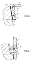
- FIG. 3 shows an embodiment of the innovation.
- the upper Tenter frame 7 consists of a profile 29, rectangular or angled as shown, and this carries on the plate 25 facing end face an all-round rectangular tube 26. In the wall facing the molded part 28 Openings 27 are provided.
- the rectangular tube 26 stands with a Compressed air source, not shown, in connection, so that - switched via a valve - compressed air at any time at short notice can be passed inside the square tube 26. This Compressed air flows through the openings 27 and cools the molded part 28 in the area of the clamping edge 30 Openings 27 are designed as bores or as slots his.
- tenter 7 from finished profiles, for. B. from Aluminum, being assembled, it is possible to be a one-piece To use profile 34, as shown in Figure 4. In one or more bores 35, 36 are provided for this, which then correspondingly with openings 37, 38 to exit the Cooling air are provided.
- the device often uses universal stenter frames used, at least in the area of the longitudinal webs. Appropriate Crossbars are used depending on the format.
- Appropriate Crossbars are used depending on the format.
- an embodiment according to Figure 5 suggested. In this case there are Openings 39 in an interchangeable setscrew 40 Openings can therefore be changed as required that set screws 40 without opening 39 or with a smaller / larger Cross section are screwed in.
- the device works as follows: If the device from Plate stack 10 works, the top plate is through the Lifting device 11 raised and inserted into the transport 15. This brings them to the forming station 1, in which they clamped between the tenter frames 6, 7 by the heater 8 heated and after lifting the table 4 with the deep-drawing mold 5 is deformed by vacuum.
- the finished molded part 28 is cooled, on the one hand by cooling fans, on the other hand by cooling air passing through openings 27, 32, 37, 38, 39 emerges in the area of the tenter frame 7. Then will the molded part 28 is demolded and transported out.
- the device works from the film roll 22, this becomes cut by the cross cutter 23 into blanks and these are processed in the same way.
- the invention can also apply to a device that only from the film roll 22 works and no cross cutter 23 having. In this case, a coherent band of Molded parts produced in a subsequent station be separated. With such a trained The heater 8 can be connected upstream of the molding station be in the area of the loading station 2, yes then does not exist.
- the invention is equally applicable to a device which only from a molding station 1 with heating 8, stenter 6, 7 and table 4 with thermoforming mold 5 and in which the Loading with plates 25 and removing the molded parts 28 done by hand.
Landscapes
- Engineering & Computer Science (AREA)
- Mechanical Engineering (AREA)
- Blow-Moulding Or Thermoforming Of Plastics Or The Like (AREA)
- Moulds For Moulding Plastics Or The Like (AREA)
Description
- Figur 1:
- Eine Längsdarstellung der Vorrichtung
- Figur 2:
- Einen Querschnitt durch die Formstation der Vorrichtung vor der Verformung
- Figur 3:
- Einen Schnitt durch den Spannrahmenbereich nach der Verformung
- Figur 4/5:
- Verschiedene Ausführungsformen des Spannrahmens.
Claims (4)
- Vorrichtung zum Verformen von erwärmten Platten oder Folienbahnabschnitten (25) aus thermoplastischem Kunststoff durch Differenzdruck, bestehend aus einer Formstation (1) mit einem Tisch (4), einer Tiefziehform (5) und zwei Spannrahmen (6, 7) zum Einspannen der Platte bzw. des Folienbahnabschnittes (25), mit Öffnungen (27, 32, 37, 38, 39) im Spannrahmen (7) zum Zuführen von Druckluft zur Kühlung des Formteils (28) sowie mit Zuführeinrichtungen für die Druckluft zu diesen Öffnungen (27, 32, 37, 38, 39) dadurch gekennzeichnet, daß die Druckluft durch das Innere von Hohlprofilen (26, 31) des Spannrahmens (7) bzw. durch längs verlaufende Bohrungen (35, 36) in den den Spannrahmen (7) bildenden Profilen (34) geführt wird, bevor sie aus den dem Formteil (28) zugewandten Öffnungen (27, 32, 37, 38, 39) austritt.
- Vorrichtung nach Anspruch 1 dadurch gekennzeichnet, daß die Öffnungen (39) zum Auslaß der Kühlluft in Gewindestifte(40) eingebracht sind, die in den Profilen (34) in der Wandung zu den Bohrungen (35, 36) angeordnet sind.
- Vorrichtung nach Anspruch 1 oder 2 dadurch gekennzeichnet, daß die Öffnungen (27, 32, 37, 38, 39) als Bohrungen ausgebildet sind.
- Vorrichtung nach Anspruch 1 oder 2 dadurch gekennzeichnet, daß die Öffnungen (27, 32, 37, 38,39) als Schlitze ausgebildet sind.
Applications Claiming Priority (2)
| Application Number | Priority Date | Filing Date | Title |
|---|---|---|---|
| DE9708716U | 1997-03-04 | ||
| DE19708716A DE19708716C2 (de) | 1997-03-04 | 1997-03-04 | Vorrichtung zum Verformen von erwärmten Platten oder Folienbahnabschnitten aus thermoplastischem Kunststoff |
Publications (2)
| Publication Number | Publication Date |
|---|---|
| EP0868993A1 EP0868993A1 (de) | 1998-10-07 |
| EP0868993B1 true EP0868993B1 (de) | 2000-04-12 |
Family
ID=7822158
Family Applications (1)
| Application Number | Title | Priority Date | Filing Date |
|---|---|---|---|
| EP98710002A Expired - Lifetime EP0868993B1 (de) | 1997-03-04 | 1998-02-20 | Kühlvorrichtung im oder am Spannrahmen für Warmumformungsmaschinen |
Country Status (3)
| Country | Link |
|---|---|
| EP (1) | EP0868993B1 (de) |
| DE (2) | DE19708716C2 (de) |
| DK (1) | DK0868993T3 (de) |
Families Citing this family (5)
| Publication number | Priority date | Publication date | Assignee | Title |
|---|---|---|---|---|
| DE19941065C1 (de) * | 1999-08-28 | 2000-12-07 | Illig Maschinenbau Adolf | Heizstation zum Beheizen von Platten aus thermoplastischem Kunststoff |
| US7390454B2 (en) * | 2004-08-19 | 2008-06-24 | General Motors Corporation | Thermoforming process for producing class “A” finish, high gloss automotive exterior parts |
| GB2474366B (en) * | 2009-10-12 | 2012-11-14 | Stretchform Associates Ltd | Zone cooling |
| DE102011088133B4 (de) | 2011-12-09 | 2024-07-04 | Bayerische Motoren Werke Aktiengesellschaft | Verfahren zur Herstellung eines dreidimensionalen Polsterkleides für einen Sitz oder dergleichen sowie ein nach dem Verfahren hergestelltes, dreidimensionales Polsterkleid |
| FR3094911B1 (fr) * | 2019-04-10 | 2022-08-12 | Novetud | Dispositif pour réaliser des pièces par thermoformage |
Family Cites Families (6)
| Publication number | Priority date | Publication date | Assignee | Title |
|---|---|---|---|---|
| US2452999A (en) * | 1944-06-28 | 1948-11-02 | Us Rubber Co | Method of making cellular thermoplastic receptacles |
| US2547275A (en) * | 1945-12-28 | 1951-04-03 | Lyon George Albert | Method of and apparatus for making plastic wheel trim |
| GB928536A (en) * | 1960-04-05 | 1963-06-12 | Parnall & Sons Ltd | Improvements relating to apparatus for chilling thermally moulded thermoplastic sheet |
| SE395599B (sv) * | 1974-02-14 | 1977-08-22 | Svenska Textilforskningsinst | Forfaringsett och anordning for formning av textila material |
| DE3220416C2 (de) * | 1982-05-29 | 1984-08-30 | Adolf Illig Maschinenbau Gmbh & Co, 7100 Heilbronn | Vorrichtung zum abfallfreien Umformen eines Bahnabschnittes aus thermoplastischem Kunststoff |
| DE3337406C2 (de) * | 1983-10-14 | 1986-06-26 | Adolf Illig Maschinenbau Gmbh & Co, 7100 Heilbronn | Vorrichtung zum abfallfreien Umformen eines Bahnabschnittes aus thermoplastischem Kunststoff |
-
1997
- 1997-03-04 DE DE19708716A patent/DE19708716C2/de not_active Expired - Fee Related
-
1998
- 1998-02-20 DK DK98710002T patent/DK0868993T3/da active
- 1998-02-20 EP EP98710002A patent/EP0868993B1/de not_active Expired - Lifetime
- 1998-02-20 DE DE59800121T patent/DE59800121D1/de not_active Expired - Lifetime
Also Published As
| Publication number | Publication date |
|---|---|
| EP0868993A1 (de) | 1998-10-07 |
| DK0868993T3 (da) | 2000-09-04 |
| DE19708716A1 (de) | 1998-09-17 |
| DE19708716C2 (de) | 1999-12-16 |
| DE59800121D1 (de) | 2000-05-18 |
Similar Documents
| Publication | Publication Date | Title |
|---|---|---|
| DE69309185T2 (de) | Presse zum Formen eines Gegenstandes aus Verbundmaterial mit verstärkenden Fasern in einer Polimermatrix | |
| DE60204133T2 (de) | Verfahren und Vorrichtung zur Herstellung von Beuteln | |
| DE1429015A1 (de) | Verfahren zum Stanzen und zur Fertigung von Packmitteln | |
| EP1127676B1 (de) | Vorrichtung zum Verformen von thermoplastischen Materialien | |
| DE2229828A1 (de) | Walzenbreitspritzkopf fuer roller-headanlagen | |
| DE3516244A1 (de) | Kuehl- und fuehrungsvorrichtung fuer folien aus thermoplastischem kunstharz | |
| AT412770B (de) | Formgebungseinrichtung für eine extrusionsanlage | |
| DE3620954C2 (de) | ||
| DE19708716C2 (de) | Vorrichtung zum Verformen von erwärmten Platten oder Folienbahnabschnitten aus thermoplastischem Kunststoff | |
| DE19629196C2 (de) | Thermoformvorrichtung | |
| DE102007011292B4 (de) | Formwerkzeug zum Aufbringen eines Etiketts auf ein tiefgezogenes Formteil und Verfahren zum Betreiben des Formwerkzeugs | |
| EP1080869A1 (de) | Heizstation zum Beheizen von Platten aus thermoplastischem Kunststoff | |
| DE3225533A1 (de) | Vorrichtung zum verformen von platten oder folienbahnabschnitten aus thermoplastischem kunststoff | |
| DE3011627A1 (de) | Schweisssiegelstation fuer verpackungsmaschinen | |
| DE1936647C3 (de) | Verfahren und Vorrichtung zum Herstellen von mit Etiketten versehenen Behältern aus thermoplastischem Kunststoff | |
| DE9006292U1 (de) | Vorrichtung zum Querschweißen und Quertrennen oder Querperforieren einer Kunststoffolienbahn | |
| DE3126216C2 (de) | ||
| EP1025978B1 (de) | Vorrichtung zum Thermoformen von Behältern aus einer Folienbahn aus thermoplastischem Kunststoff | |
| DE2716680C2 (de) | Vorrichtung zum Formen, Stanzen und Stapeln von Teilen aus thermoplastischer Kunststoffolie | |
| EP3672778B1 (de) | Vorform-vorrichtung zum positionieren von extrudierten kautschukmischungen und ein die vorform-vorrichtung aufweisendes extruder-form-system zum ausformen von extrudierten kautschukmischungen zu einem gesamtkautschukelement sowie eine entsprechende extruderanlage | |
| DE4033672A1 (de) | Vorrichtung zur warmverformung von kunststoffplatten | |
| DE3830889A1 (de) | Inline-thermoformmaschine | |
| EP0985514B1 (de) | Verriegelungseinrichtung zum Verriegeln bzw. Befestigen von unterschiedlich grossen Formwerkzeugen auf der Warmvormmaschine | |
| DE1997665U (de) | Vorrichtung zur herstellung von verpackungsbehaeltern | |
| EP0884161B1 (de) | Form- oder Stanzstation |
Legal Events
| Date | Code | Title | Description |
|---|---|---|---|
| PUAI | Public reference made under article 153(3) epc to a published international application that has entered the european phase |
Free format text: ORIGINAL CODE: 0009012 |
|
| 17P | Request for examination filed |
Effective date: 19980716 |
|
| AK | Designated contracting states |
Kind code of ref document: A1 Designated state(s): BE DE DK ES FR GB IT |
|
| 17Q | First examination report despatched |
Effective date: 19981130 |
|
| AKX | Designation fees paid |
Free format text: BE DE DK ES FR GB IT |
|
| GRAG | Despatch of communication of intention to grant |
Free format text: ORIGINAL CODE: EPIDOS AGRA |
|
| GRAH | Despatch of communication of intention to grant a patent |
Free format text: ORIGINAL CODE: EPIDOS IGRA |
|
| GRAH | Despatch of communication of intention to grant a patent |
Free format text: ORIGINAL CODE: EPIDOS IGRA |
|
| GRAA | (expected) grant |
Free format text: ORIGINAL CODE: 0009210 |
|
| AK | Designated contracting states |
Kind code of ref document: B1 Designated state(s): BE DE DK ES FR GB IT |
|
| PG25 | Lapsed in a contracting state [announced via postgrant information from national office to epo] |
Ref country code: ES Free format text: THE PATENT HAS BEEN ANNULLED BY A DECISION OF A NATIONAL AUTHORITY Effective date: 20000412 |
|
| GBT | Gb: translation of ep patent filed (gb section 77(6)(a)/1977) |
Effective date: 20000413 |
|
| ITF | It: translation for a ep patent filed | ||
| REF | Corresponds to: |
Ref document number: 59800121 Country of ref document: DE Date of ref document: 20000518 |
|
| ET | Fr: translation filed | ||
| REG | Reference to a national code |
Ref country code: DK Ref legal event code: T3 |
|
| PLBE | No opposition filed within time limit |
Free format text: ORIGINAL CODE: 0009261 |
|
| STAA | Information on the status of an ep patent application or granted ep patent |
Free format text: STATUS: NO OPPOSITION FILED WITHIN TIME LIMIT |
|
| 26N | No opposition filed | ||
| REG | Reference to a national code |
Ref country code: GB Ref legal event code: IF02 |
|
| REG | Reference to a national code |
Ref country code: FR Ref legal event code: CD Ref country code: FR Ref legal event code: CA |
|
| REG | Reference to a national code |
Ref country code: FR Ref legal event code: CD |
|
| REG | Reference to a national code |
Ref country code: FR Ref legal event code: PLFP Year of fee payment: 19 |
|
| REG | Reference to a national code |
Ref country code: FR Ref legal event code: PLFP Year of fee payment: 20 |
|
| PGFP | Annual fee paid to national office [announced via postgrant information from national office to epo] |
Ref country code: DE Payment date: 20170217 Year of fee payment: 20 Ref country code: FR Payment date: 20170220 Year of fee payment: 20 |
|
| PGFP | Annual fee paid to national office [announced via postgrant information from national office to epo] |
Ref country code: BE Payment date: 20170220 Year of fee payment: 20 Ref country code: DK Payment date: 20170222 Year of fee payment: 20 Ref country code: GB Payment date: 20170221 Year of fee payment: 20 |
|
| PGFP | Annual fee paid to national office [announced via postgrant information from national office to epo] |
Ref country code: IT Payment date: 20170217 Year of fee payment: 20 |
|
| REG | Reference to a national code |
Ref country code: DE Ref legal event code: R071 Ref document number: 59800121 Country of ref document: DE |
|
| REG | Reference to a national code |
Ref country code: DK Ref legal event code: EUP Effective date: 20180220 |
|
| REG | Reference to a national code |
Ref country code: GB Ref legal event code: PE20 Expiry date: 20180219 Ref country code: BE Ref legal event code: MK Effective date: 20180220 |
|
| PG25 | Lapsed in a contracting state [announced via postgrant information from national office to epo] |
Ref country code: GB Free format text: LAPSE BECAUSE OF EXPIRATION OF PROTECTION Effective date: 20180219 |