The present invention relates to a normal
temperature-operating electrolyte fuel cell for use in
such applications as a portable power source, an electric
vehicle and a home powder source system.
The normal temperature-operating polymer
electrolyte fuel cell generates electricity by
electrochemically reacting a fuel gas such as hydrogen and
an oxidizer gas such as oxygen. The heat, which
simultaneously comes out in the reaction, is also made
good use of.
The basic construction composing a polymer
electrolyte fuel cell is configured as in the following,
for example. A polymer electrolyte film is made of a
hydrogen ion conductive resin such as a fluorocarbon resin
having a sulfo group. A catalytic layer substantially
made of a carbon powder with a platinum group metal
catalyst carried thereon is formed closely on each
surface of the polymer electrolyte film. Furthermore, a
gas-permeable and electrically conductive electrode layer
is provided directly on the outer surface of each
catalytic layer. On the outer surface of the electrode
layer, an electrically conductive separator is provided to
mechanically clamp the assembly composed of the electrode
layers and the polymer electrolyte film and to
electrically connect the assembly with the adjoining
assembly in series. A groove-shaped channel to evenly
supply the gas to the electrode layer is formed on the
surface of the separator facing the electrode layer. The
fuel gas is supplied to one of the pair of the electrode
layers, and the oxidizer gas is supplied to the other.
Hereafter described an arrangement in which hydrogen is
used as the fuel gas and oxygen as the oxidizer gas.
A hydrogen gas supplied from outside is taken in
the electrode layer on the hydrogen gas supplying side or
the anode while passing along the surface of the electrode
layer. The hydrogen gas taken in the electrode layer
diffuses and passes through the electrode layer, then
reaches the catalytic layer. When the hydrogen gas flows
inside the catalytic layer and reaches a region where the
polymer electrolyte coexists, an electrochemical reaction
is caused between the hydrogen gas and the polymer
electrolyte. The hydrogen gas is ionized by the reaction,
and the generated hydrogen ions are taken into the polymer
electrolyte film.
On the other hand, an oxygen gas supplied from
outside is taken in the electrode layer on the oxygen gas
supplying side or the cathode while passing along the
surface of the electrode layer. The oxygen gas diffuses
and passes through the electrode layer, then reaches the
catalytic layer on the cathode side. Then, the oxygen gas
turns into water vapor by reacting with hydrogen ions
drifting from the anode through the electrolyte film. In
this reaction, the electrons migrate from the anode to the
cathode through an external load connected to the fuel
cell. This migration of the electrons is utilized as an
electric power. This electrochemical reaction between
hydrogen and oxygen further produces heat. Therefore, a
cooling water is circulated through the inside of the fuel
cell to keep the temperature of the fuel cell low, and the
warmed water is utilized as a thermal energy.
The polymer electrolyte fuel cell is usually
operated in a temperature range from a room temperature to
about 80°C. Therefore, the water vapor generated by the
electrochemical reaction on the catalytic layer on the
cathode side mostly condenses into dew around the
catalytic layer. When the condensed water remains around
the catalytic layer, the oxygen gas is prevented from
reaching the reaction area or the catalytic layer, and
hence the cell performance is lowered. On the anode side,
meanwhile, no water is generated. However, in a case the
water generated on the cathode side permeates through the
polymer electrolyte film and penetrates into the catalytic
layer, or in a case the water vapor which is previously
mixed into the fuel gas to prevent the electrolyte film
from drying up condenses into dew and remains on the
catalytic layer, the supply of hydrogen to the reaction
area is blocked and the cell performance is dropped.
To solve the problems, various countermeasures
have been proposed and tried, which include a water-repellent
finish of the electrode layers to maintain the
reaction area or the catalytic layers in a good wet
condition, and an increased flow velocity of the gas
flowing along the surface of the electrode layers so as to
remove an excessive water sticking to the electrode
layers.
However, the employment of the water repellent
finished electrode layer causes a problem of hardly
removing the water, resulting in a decreased cell
performance, under some operating conditions as, for
example, a high current density output operation which
generates a large quantity of water or a low gas flow
velocity operation. In some serious cases, the gas
channels on the surfaces of the electrode layers are
clogged, with the output of the cell dropping to zero.
It is an aim of the present invention to
solve the foregoing problem and to provide a polymer
electrolyte fuel cell which can facilitate a removal of
water around the catalytic layer of the cell, thereby to
prevent the cell performance from dropping due to
excessive wetting of the electrode layer as in the long-hour
operation or the high current density output
operation.
The present invention provides a polymer
electrolyte fuel cell comprising:
In a preferred mode of the polymer electrolyte
fuel cell of the present invention, the electrode layer is
mainly composed of the porous base area and a plurality of
the penetration areas which are scattered over the base
area.
In another preferred mode of the polymer
electrolyte fuel cell of the present invention, the
penetration area is formed through the electrode layer.
The foregoing base area and penetration areas
can be formed, for example, by adding water-repellency to
a hydrophilic porous material unevenly and ununiformly.
Most of the electrode layer surface is water repellent
finished, however the scattering untreated areas or the
penetration areas are also provided sparsely. The water
repellent finish is carried out with a water repellent
agent containing a fluorocarbon resin, for example.
While the prior art water repellent finish has
been effected uniformly all over the surface of the
electrode layer, the present invention uses the uneven
water repellent finish to realize coexistence of the
water-repellent area and the untreated areas in the porous
material formed. This facilitates the oozing of water
generated on the catalytic layer into the gas channels
through the untreated areas. The random scattering of the
wet spots or the water repellent areas wherein water lie
stagnant and the gas-flowing spots or the untreated areas
accelerates the gas flow velocity. This, it is
considered, makes it easy to remove excessive water being
stagnate within the electrodes.
The penetration areas can be formed of holes
made by perforating through the electrode layer excepting
the gas permeable pores originally possessed by the porous
material. Since water tends to penetrate through larger
openings in the water repellent porous material, the
excessive water oozes through the formed holes. As a
result, the removal of water by the gas flow is
facilitated.
Even if the penetration areas are water
repellent, in the case that the penetration areas has
larger pores than those in the base area, water drops
penetrate the pores in the penetration areas and thus the
same results can be obtained.
When the penetration areas are arranged on the
electrode layer so as to face the gas channel, more
preferably along the center line of the gas channel where
the gas flow velocity is high, water can be removed more
efficiently thereby obtaining higher effects.
The present invention also provides a polymer
electrolyte fuel cell comprising an electric generator
including:
In a preferred mode of the polymer electrolyte
fuel cell according to the present invention, the vibrator
is an ultrasonic vibrator which produces vibration
intermittently or interlocked with the cell performance.
Applying vibration with a relatively low frequency is more
effective in removal of the water which overflows and
blocks the gas channels than the water which blocks the
permeable pores in the electrode. Vibration with a high
frequency like ultrasonic, on the other hand, can remove
the water which blocks the permeable pores in the
electrode more efficiently.
The present invention further provides a polymer
electrolyte fuel cell comprising an electric generator
including:
Since the velocity of the gases flowing along
the catalytic and the electrode layers can be raised
temporarily by providing a compressor on the gas supply
means and by intermittently increasing the gas flow
velocity, stagnating condensed water can be removed
efficiently.
While the novel features of the invention are
set forth particularly in the appended claims, the
invention, both as to organization and content, will be
better understood and appreciated, along with other
objects and features thereof, from the following detailed
description taken in conjunction with the drawings.
BRIEF DESCRIPTION OF THE SEVERAL VIEWS OF THE DRAWING
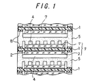
FIG. 1 is a cross-sectional view showing the
main part of the polymer electrolyte fuel cell in an
embodiment of the present invention.
FIG. 2 is a characteristics diagram showing the
change with time in the output voltage of the same polymer
electrolyte fuel cell.
FIG. 3 is a characteristics diagram showing a
change with time in an output voltage of a polymer
electrolyte fuel cell in another embodiment of the present
invention.
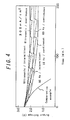
FIG. 4 is a characteristics diagram showing a
change with time in an output voltage of a polymer
electrolyte fuel cell in still another embodiment of the
present invention.
DETAILED DESCRIPTION OF THE EMBODIMENTS
Preferred embodiments of the present invention
are hereinafter described in detail with reference to the
attached drawings.
EMBODIMENT 1
A carbon powder with a particle diameter of
several µm was dipped in an aqueous solution of
chloroplatinic acid. The carbon powder was then subjected
to a reduction treatment to carry a platinum catalyst
thereon. The ratio of the carbon powder to the carried
platinum was 1 to 1 by weight. The carbon powder with
platinum was then dispersed in an alcoholic solution of a
polymer electrolyte to give a slurry.
Meanwhile, an aqueous dispersion of a
fluorocarbon resin ("Neofreon ND-1" manufactured by Daikin
Industries, Ltd., Japan) was applied by splashing onto the
both surfaces of a carbon unwoven fabric with a thickness
of 400 µm to be employed as an electrode so that the
surfaces of the carbon unwoven fabric were coated unevenly
with the fluorocarbon resin powder. The carbon unwoven
fabric was then dried, followed by a heat treatment at
400°C to produce a carbon unwoven fabric electrode.
The obtained carbon unwoven fabric electrode as
a whole showed water repellency when wetted with water,
but the water penetrated inside in time. By a microscopic
observation of the surface and the section of the carbon
unwoven fabric electrode, it was confirmed that there were
scattered regions 30 µm to several mm in width where no
fluorocarbon resin is applied.
In parallel with that, the same kind of carbon
unwoven fabric was uniformly coated with the aqueous
dispersion of the fluorocarbon resin and heat-treated.
When this unwoven fabric was wetted with water, large
water drops were formed on the surface of the unwoven
fabric and would not penetrate inside even in part.
One surface of each carbon unwoven fabric
electrode thus water repellent finished was coated
uniformly with the aforementioned slurry containing carbon
powder and then dried to form a catalytic layer. A
polymer electrolyte film 1 with a thickness of 50 µm made
of a fluorocarbon resin having a sulfo group was
sandwiched between two pieces of the carbon unwoven fabric
electrodes 7 so placed as to face the catalytic layer 2
each other. They were then dried to obtain an assembly 9
shown in FIG. 1. The carbon unwoven fabric electrodes 7
were 5 cm in length and width, while the polymer
electrolyte film 1 was 8 cm in length and width. The
carbon unwoven fabric electrodes 7 were put in the center
of the polymer electrolyte film 1. In the assembly 9 thus
obtained, it was confirmed that the polymer electrolyte
film 1 and the carbon unwoven fabric electrode 7 were
firmly bonded each other via the catalytic layer 2 where
the platinum-carrying carbon powder and the polymer
electrolyte coexisted.
The assemblies 9 and an airtight carbon
separator plates 5 were piled alternately to give a three-cell
unit as shown in FIG. 1. The separator plate 5 was 4
mm in thickness and has a plurality of channels 4 of 1 mm
in width and depth, provided in one direction by cutting
the surface thereof. A seal material 8 was interposed
between the separator plate 5 and the polymer electrolyte
1 to provide an electrical insulation therebetween and to
prevent leakage of the gases inside.
End plates, which also serve as cooling plates,
were placed on the both ends of the piled cells and the
three cells were pressed and clamped under a pressure of
10 kgf/cm2 in the piled direction. Characteristics tests
were carried out with thus obtained three-cell unit as
follows. A hydrogen gas as a fuel gas was supplied to the
anode with the utilization of 60%. On the other hand, an
air as an oxidizer gas was supplied to the cathode with
the utilization of 20%. A temperature controller was
provided on each gas supply unit, which was so set that
the temperature of the supply gas was, in principle,
identical with that of the cell. A humidifier is also
provided on each gas supply unit, and the humidity was so
adjusted that the dew point of the supply gas was 15 to
35°C lower than the cell temperature.
FIG. 2 shows the characteristics change with
time when the three-cell unit of the present embodiment
was operated with an output current density of 300 mA/cm2.
FIG. 2 also shows the characteristics of the prior art
three-cell unit with the uniformly water repellent
finished electrodes as a comparative example. The output
voltage of the comparative example dropped sharply 30
minutes after the start of operation and ran out of power
some 60 minutes later. The three-cell unit of the present
embodiment, on the other hand, maintained the performance
high for a long time though the output dropped slightly in
the initial stage.
EMBODIMENT 2
Another method of providing the electrode layers
with an uneven water repellent finish will be described in
the present embodiment.
A paraffin powder with a melting point of 60 to
90°C and a particle diameter of 0.01 to 0.2 mm was
scattered over the surface of a carbon unwoven fabric 400
µm in thickness. The unwoven fabric was then stored for
30 minute in a thermostatic chamber maintained at 120°C.
The paraffin powder scattered on the unwoven fabric melted
and penetrated into the unwoven fabric by the heat
treatment. The unwoven fabric was then taken out of the
thermostatic chamber and was allowed to cool to a room
temperature. An observation of this unwoven fabric
confirmed penetrations of paraffin in the shape of
cylinder 0.02 to 1 mm in diameter through the unwoven
fabric.
This unwoven fabric was dipped in the same
aqueous dispersion of fluorocarbon resin powder as used in
Embodiment 1 and dried. The material was then subjected
to a heat treatment for some one hour at 400°C. Paraffin
evaporates in the initial stage of such heat treatment,
and the fluorocarbon resin powder which has stuck to the
unwoven fabric by the dipping peels off in the heat
treatment. Thus, the areas where paraffin stuck on the
unwoven fabric are left uncoated with fluorocarbon resin
in the heat treatment. On the areas with no paraffin, on
the other hand, the fluorocarbon resin powder sticks
directly to the unwoven fabric when the material is dipped
in the dispersion. The fluorocarbon resin sticking
directly to the fabric melts thereby forming a water
repellent coating on the unwoven fabric by the heat
treatment. In the unwoven fabric thus treated, the water
repellent areas and the highly wettable areas coexist,
each extending from one surface to the other.
When the treated unwoven fabric was actually
wetted with water on the surface, it was confirmed that
water passed from one side to the other through the highly
wettable areas where no fluorocarbon resin was coated. A
three-cell unit was assembled using the water repellent
finished unwoven fabric in the same manner as in
Embodiment 1. The obtained three-cell unit was operated
with an output current density of 300 mA/cm2 in the same
way as in Embodiment 1. As a result, a stable output
voltage continued for not shorter than 1,000 minutes.
EMBODIMENT 3
In the present embodiment, there will be
explained a method of controlling the water permeability
of the electrode layer through the pore diameter of a
water repellent porous material.
A carbon unwoven fabric 400 µm in thickness was
coated with fluorocarbon resin by dipping in the same
aqueous dispersion of fluorocarbon resin powder as used in
Embodiment 1. The unwoven fabric was then heat-treated
for some one hour at 400°C to form a fluorocarbon resin
coating on the surface.
The unwoven fabric thus uniformly water
repellent finished was roughly loosened into small pieces.
These small pieces were immersed into an aqueous solution
containing proper amounts of a surfactant and
carboxymethylcellulose as a binder, then the solution was
stirred. When the solution was stirred, some of the
unwoven fabric pieces broke up into single fibers, but
other fibers remained in lumps.
Those fibers were refabricated into a unwoven
fabric. The remade unwoven fabric had two types of
regions, dense regions made up of fibers that had not been
dispersed by the foregoing stirring and coarse regions
formed of fibers that had been dispersed apart by the
stirring and reassembled.
In water repellent porous materials as the
aforementioned unwoven fabric, the water permeability
depends on the diameter of pores on the surface. That is
to say, the larger the diameter, the easier the water
penetration. In the foregoing unwoven fabric, the water
permeability on the coarse regions is higher than that on
the dense regions, and water sticking to the surface of
such porous material tends to move toward the coarse
regions.
A polymer electrolyte fuel cell was assembled
using the remade unwoven fabric in the same manner as in
Embodiment 1. The three-cell unit obtained was operated
with an output current density of 300 mA/cm2 in the same
way as in Embodiment 1. A stable output voltage continued
for not shorter than 1,000 minutes. That is, it was
confirmed that the water generated by the electrode
reaction and the condensed water can be removed through
the coarse regions on the electrode layer.
EMBODIMENT 4
In the present embodiment, there will be
explained a method of facilitating the removal of water
generated on the catalytic layers by forming holes
therethrough.
Carbon unwoven fabrics were uniformly water
repellent finished by dipping in the same aqueous
dispersion of fluorocarbon resin powder as used in
Embodiment 1. Then, a plurality of fine through holes
were formed in the carbon unwoven fabrics using a carbonic
acid gas laser. Four kinds of three-cell units were
assembled using the unwoven fabrics, each with a different
hole size and hole arrangement, in the same manner as in
Embodiment 1. Cell unit "A" was assembled using the
carbon unwoven fabrics with 3 to 5 holes/cm2, each 50 µm
in diameter, cut randomly on the surface. Cell unit "B"
was assembled using the carbon unwoven fabrics on which 50
µm-diameter holes were formed along the center line of the
opposite gas channel of the separator plate at an interval
of 3 mm. Cell unit "C" was assembled using the same
carbon unwoven fabrics as used in Cell unit "A" but has
the hole diameter of 100 µm. Cell unit "D" was assembled
using the same carbon unwoven fabric as used in Cell unit
"B" but has the hole diameter of 100 µm. It is noted that
the hole diameter was so chosen as to be some 10 times the
diameter of the carbon fiber used in the carbon unwoven
fabric.
The four kinds of three-cell units were tested
with regard to the change with time in characteristics.
The results are illustrated in FIG. 3.
As shown in FIG. 3, all of the three-cell units
in the present embodiment exhibited a long and stable
output voltage unlike the comparative cell units using
unwoven fabrics with no perforated hole. FIG. 3 shows the
characteristics changes at a current density of 300
mA/cm2, a hydrogen utilization of 60% and an air
utilization of 20%.
When the three-cell units were tested at a
current density of 500 mA/cm2 with a hydrogen utilization
of 60%, especially good results were obtained with Cell
unit "B" and Cell unit "D" which had been assembled with
the carbon unwoven fabrics on which the through holes were
formed regularly along the center line of the gas channels
of the opposite separator plate. It was also indicated
that Cell unit "C" with the fabrics with 100 µm-diameter
holes gave better results than Cell unit "D" with the
unwoven fabric with 50 µm-diameter holes. That is
probably because with rise in current density or
utilization, the flow velocity of the gas that carries
away water decreases in relation to the generation rate of
water to be removed, and large holes can eliminate the
water more efficiently.
EMBODIMENT 5
In the present embodiment, there will be
explained a method of facilitating the discharging the
water generated on the catalytic layer out of the unit by
applying vibration to the cell.
Three cells of the prior art used as comparison
example in Embodiment 1 were piled. A pair of metal end
plates were provided on the both ends of this laminate.
The end plates were then connected to each other via
connecting members so as to compress the cells. Thus a
three-cell unit (with an electrode area of 100 cm2) was
obtained. The three-cell unit thus obtained was mounted
on a mechanical vibrator stand and then vibrated
continuously or intermittently at a rate of 1 to 50 cycles
per second.
Separately, to apply vibration of a higher
frequency, an ultrasonic vibration plate employing an
ultrasonic piezoelectric transducer (output of 50 W) was
screwed to the end plates of a similar three-cell unit.
As an electrically insulating plate, an acrylic resin
plate which was right, hard and low in sound wave
attenuation was interposed between the end plate and the
three-cell unit in order to use the ultrasonic efficiently
for eliminating the generated water. An electric circuit
to adjust the magnitude and output time of the ultrasonic
piezoelectric transducer was also mounted on an ultrasonic
piezoelectric transducer.
The three-cell unit was supplied with a hydrogen
gas and an air in such a way that the utilization of the
hydrogen gas on the anode side was 60% and the air
utilization on the cathode side was 20%. A temperature
controller and a humidifier were provided on each gas
supply unit, which were so set that the temperature of the
supply gas was identical with that of the cell and the dew
point of the supply gas was 15 to 35°C lower than the
temperature of the cell unit.
FIG. 4 shows the changes in the output voltage
of the three-cell units provided with the vibrator during
a relatively short time period.
As outputting continued at a current density of
300 mA/cm2, the output voltage of the three-cell unit of
the comparative example with no vibrator dropped sharply
30 minutes after start of operation, and the three-cell
unit was exhausted some 60 minutes later. It is shown in
comparison that the three-cell units of the present
embodiment all improved in performance as vibration was
applied. The prior three-cell unit as the comparative
example continued to fall in output voltage with the lapse
of time. On the other hand, the three-cell units of the
present embodiment which were vibrated on the vibration
stand fell in performance in the initial stage but reached
a normal state in certain stages. This effect was more
remarkable with a higher vibration frequency. The system
of applying vibration of a relatively low frequency on
such a mechanical vibrator stand, it appears, is not so
effective in removing the water which blocks the gas
permeable pores on the electrode but can effectively
eliminate the water which overflows and blocks the gas
channels.
Applying ultrasonic to the three-cell unit was
very effective in facilitating the removal of the water.
Especially the three-cell unit which was subjected to
continuous ultrasonic vibration showed little fall in
performance from immediately after the start of operation.
This indicates that vibrations of a high frequency are
more effective in eliminating the water which blocks the
gas permeable pores on the electrode. It was also found
that the performance of the three-cell unit in which the
ultrasonic piezoelectric transducer was activated on and
off or intermittently fell slightly when the piezoelectric
transducer was stopped but soon recovered after the
transducer was restarted. Considering the energy
efficiency, noise, mechanical wear of the cell unit by
vibration and other factors, therefore, the system of
activating the piezoelectric transducer intermittently is
more attractive for practical application.
EMBODIMENT 6
In the present embodiment, there will be
explained a method of facilitating the removal of the
water stagnating around the catalytic layers and the
electrode layers by intermittently increasing the pressure
of the gas supplied to the cell.
A three-cell unit (with an electrode area of 100
cm2) assembled by piling three of the same cells as used
as comparison example in Embodiment 1 was mounted with a
cylinder pomp (cylinder volume of 1,000 cm3) to a gas pipe
for supplying the anode gas and to the other gas pipe for
supplying the cathode gas so that each gas taken in the
cylinder pomp could be discharged into the gas pipe
instantly and intermittently. In addition, a gas check
valve was mounted on the upstream side of cylinder pomp on
each gas pipe, so that pressure might be effectively felt
in the three-cell unit with no reverse flow of the gas
discharged from the cylinder pomp. A pressure sensor was
provided near each joint to the cell unit, and an
electrical drive unit interlocked with the pressure sensor
for driving the cylinder pomp to apply pressure on the gas
was mounted on the cylinder pomp.
The three-cell unit equipped with that pressure
application unit was tested to examine the change with
time in characteristics. When the pressure application
unit was not activated, the three-cell units of the
present embodiment fell in performance too much to run any
more some 60 minutes after the start in the continuous
operation at a current density of 300 mA/cm2 as in the
case with the prior three-cell unit. But when a pressure
of 5,000 to 10,000 Pa was applied for 0.5 seconds at an
interval of 10 minutes, the three-cell units recovered the
original performance each time. This indicates that
intermittent compression of the supply gas increased
temporarily the flow velocity of the gas flowing in the
catalytic layers and the electrode layers, thereby
eliminating the stagnating water.
In the above embodiment, the application of
pressure on the anode side was synchronized with that on
the cathode side in consideration of possible damages on
the cell such as breakage of the film. But the two sides
can be compressed independently of each other. Also, the
application of pressure can be confined to the anode side
or the cathode side alone with good results.
As to the time of applying pressure, it was
found that 0.5 to 1.0 seconds was enough for the three-cell
units used in the above embodiment to recover the
original output characteristics. It appears that the time
depends on the internal configuration of the cell system.
Therefore, the duration of applying pressure is freely
chosen for different cell unit configurations. The
pressure to be applied is also decided on taking into
consideration the internal structure of the cell unit and
other factors.
In the present embodiment, it is further noted,
a gas cylinder pomp was used as means for applying
pressure. Other means can be used instead, including a
system consisting of an auxiliary gas cylinder and an
electromagnetic valve.
As described, the present invention can
effectively remove out of the cell unit the water
stagnating around the catalytic layers and the electrode
layers of the fuel cell, ensuring smooth supply of oxygen
to the reaction area on the catalytic layers. Thus, the
present invention provides a fuel cell which can maintain
the performance at a high level for a long time.
Although the present invention has been
described in terms of the presently preferred embodiments,
it is to be understood that such disclosure is not to be
interpreted as limiting. Various alterations and
modifications will no doubt become apparent to those
skilled in the art to which the present invention
pertains, after having read the above disclosure.
Accordingly, it is intended that the appended claims be
interpreted as covering all alterations and modifications
as fall within the scope of the invention.