EP0867314B1 - Fahrzeuganhänger mit höhenverstellbarer Achsbockbefestigung - Google Patents
Fahrzeuganhänger mit höhenverstellbarer Achsbockbefestigung Download PDFInfo
- Publication number
- EP0867314B1 EP0867314B1 EP98105452A EP98105452A EP0867314B1 EP 0867314 B1 EP0867314 B1 EP 0867314B1 EP 98105452 A EP98105452 A EP 98105452A EP 98105452 A EP98105452 A EP 98105452A EP 0867314 B1 EP0867314 B1 EP 0867314B1
- Authority
- EP
- European Patent Office
- Prior art keywords
- axle
- chassis
- vehicle trailer
- screw holes
- trailer according
- Prior art date
- Legal status (The legal status is an assumption and is not a legal conclusion. Google has not performed a legal analysis and makes no representation as to the accuracy of the status listed.)
- Expired - Lifetime
Links
- 230000008878 coupling Effects 0.000 description 4
- 238000010168 coupling process Methods 0.000 description 4
- 238000005859 coupling reaction Methods 0.000 description 4
- 238000010276 construction Methods 0.000 description 3
- 238000009434 installation Methods 0.000 description 1
- 230000004048 modification Effects 0.000 description 1
- 238000012986 modification Methods 0.000 description 1
- 125000006850 spacer group Chemical group 0.000 description 1
- 239000000725 suspension Substances 0.000 description 1
Images


Classifications
-
- B—PERFORMING OPERATIONS; TRANSPORTING
- B62—LAND VEHICLES FOR TRAVELLING OTHERWISE THAN ON RAILS
- B62D—MOTOR VEHICLES; TRAILERS
- B62D63/00—Motor vehicles or trailers not otherwise provided for
- B62D63/06—Trailers
- B62D63/062—Trailers with one axle or two wheels
Definitions
- the invention relates to a vehicle trailer in the form of an uploader with the features in the preamble of Main claim.
- DE-U 91 03 811 shows generic vehicle trailers conventional chassis for caravans and the like one or two sprung axles with two wheel control arms and two end axles and one Have axle bracket attachment. Can on the chassis a structure can be arranged. With these vehicle trailers is an adjustable length between body and axle possible to change the focus and To be able to use standard drawbars.
- the arrangement of a length-adjustable axis have Longitudinal bars a closed underside without Axle section, with the axle support over a longitudinal row of mounting holes is adjustable.
- a vehicle trailer is known from FR-A-2 371 333, the on sprung central axles with axles at the ends waived and instead independent suspension provides that from short angled axle beams with axle bolts for the wheels that are overhung at the ends consist.
- the longitudinal and cross members of the chassis have several shafts open to the side or downwards several attachment points for adjustable mounting of the Axle. Due to the adjustable axle support, the Track width of the trailer, its height above the ground and the Trailer orientation changed lengthways or crossways can be. The drawbar can also be started different places depending on the orientation of the Attach the trailer.
- the invention solves this problem with the features in Main claim.
- the vehicle trailer according to the invention is with a height-adjustable trestle attachment equipped it allowed to work with a unit axis and this via the variable axle bracket attachment to different Fit tire sizes adapted.
- a unit axis can on the one hand the axis angle despite different mounting heights are kept constant. Above all, the construction and cost is essential reduced because the unit axis for different Vehicle trailer can be used. Special advantages exist for the uploaders.
- the height-adjustable axle bracket has one Screw register with several vertical rows of screw holes, the rows of screw holes preferably on axles are arranged and with predetermined screw holes on Interact with the chassis. It is particularly advantageous here, at least part of the screw holes Cup-shaped interlocking wall deformations equip and preferably at the lower end of the To arrange axis cutout. That way they can Axle forces are particularly well supported on the chassis, the axis section including the Shear forces are bridged and stabilized.
- the vehicle trailer according to the invention also makes it possible to provide a uniform chassis with at least uniform longitudinal spars and to use an auxiliary frame for fastening variable structures with different height requirements or for different tire sizes.
- the variable axle bracket attachment can act on the chassis and the subframe, which brings additional stability.
- FIG. 1 shows a vehicle trailer (1) which has a rigid drawbar (2) with an end-side trailer coupling (19) and one or two axles (6).
- the trailer coupling (19) is preferably designed as a ball head coupling and can include an overrun brake.
- the chassis (3) is formed by the drawbar (2) and at least two longitudinal spars, which are optionally additionally supported by crossbeams.
- the axles (6) are fastened with their end axles (7) to the longitudinal spars (3).
- a height-adjustable axle support (9) is provided, which allows the axles (6) to be mounted at different heights on the chassis (3) in the manner described below.
- the vehicle trailer (1) is designed as a so-called high loader, in which the structure (4) is arranged at a distance above the vehicle wheels (21). The height distance also takes into account the necessary travel.
- the structure (4) can be designed in any suitable manner.
- Figure 2 shows the frequent application of a flatbed.
- the Chassis (3) an auxiliary frame (5) can be mounted on the the structure (4) is at rest. This enables the use of a uniform chassis (3) for different Vehicle trailer, the required height distances the structure (4) via adapted subframe (5) of the Bodybuilder.
- axles (6) are for different Different installation heights of the axle (6) required.
- the longitudinal bars (3) point to the Axis (6) has a downward open axis cutout (8).
- the axles (6) are preferably with straight link axles a rubber or torsion spring element and wheel control levers educated.
- the vehicle trailer (1) has a height adjustable Axle bracket mounting (9), which allows the axle (6) each according to the wheel diameter at different heights Fasten the chassis (3) or on the subframe (5).
- the Axle bracket mounting (9) has a screw register (10) with several vertical rows of screw holes (11, 12), which the offer said height adjustability.
- screw holes (11, 12) are preferably the screw hole rows (11, 12) on the Axle blocks (7) arranged.
- part of the screw holes is (13,14) on the axle support (7) and on the chassis (3) or Subframe (5) as simple through holes for Screws (18) or other suitable fastening means educated.
- Another part of the screw holes (15, 16) on Chassis (3) and on the axle support (7) have a cup shape interlocking wall deformations (17). These wall deformations (17) offer a positive fit Support and guidance of the adjacent sheets from Axle bracket (7) and longitudinal spars (3) and allow the inclusion of lateral forces.
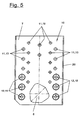
- Figure 3-5 illustrate the individual training.
- On the axle support (7) are two rows of screw holes on both sides of the axis (6) (12) each with three cup-shaped screw holes (15) arranged.
- further rows of screw holes (11) with simple through holes (13) can be arranged.
- Between the rows of screw holes (12) and essentially above are two also vertical distant from the center Row of screw holes (11) with simple through holes (13) arranged.
- In the upper area of the axle support (7) can have more through holes in the center line to be available.
- the screw register (10) with the Screw hole rows (11) is designed so that a part the through holes (13) with the corresponding Counterbores on the longitudinal spar (3) and another part of the Screw holes (13) with corresponding through holes cooperates on the subframe (5). Through this Double attachment of the axle bracket (7) to the longitudinal spars (3) and on the subframe (5) these latter Parts are fixed against each other, which if necessary further fastenings between chassis (3) and Subframe (5) can be saved.
- Figure 3 illustrates the arrangement on the longitudinal spar (3) in Area of the axis cutout (8).
- both sides of the Axis section (8) in its lower area two Cup-shaped screw holes (16) are provided.
- At the top Area of the axis section (8) are two as Through holes formed screw holes (14) available, which are preferably a little further together than the cup-shaped screw holes (16). More than Through holes trained screw holes can on Subframe (5) may be arranged, which is not here is shown.
- Figure 4 shows this training of Longitudinal spar (3) in a cross section.
- the Screw hole arrangement on the longitudinal bars (3) and subframe (5) are the cup-shaped screw holes (15) on the axle support (7) arranged in the lower area near the axis (6), while those designed as through holes Screw holes (13) above or in the upper axle support area can be found.
- Figure 6-8 show the height-adjustable axle bracket attachment (9) in different mounting positions, Figure 6 shows the subscript that corresponds to the left part of FIG. 2 equivalent.
- the axis (6) is at a distance below the axis cutout (8).
- Cup-shaped screw holes (15) are in both Rows of the upper screw holes (15) occupied and reach positively over the chassis side Screw holes (16).
- Over the as through holes trained screw holes (13) are the subframes (5) and the chassis (3) is screwed to the axle bracket (7).
- Figure 6-8 also illustrate that the axle bracket (7) on the vertical side edges transversely projecting flanges (20) for Can have stiffening.
- Figure 7 shows the middle position, in the rows of screw holes (12) the middle cup-shaped Screw holes (15) of the axle bracket (7) are occupied. The other cup-shaped screw holes (15) are free. In In this mounting position, the top and bottom simple screw holes (14) on the subframe (5) his.
- Figure 8 shows the upper mounting position, that of the right Representation of Figure 2 corresponds.
- the axis (6) is in the axis cutout (8).
- In this mounting position is from the screw hole rows (12) each occupied the lower cup-shaped screw hole (15).
- FIGS. 17 and 6-8 illustrate, these are Wall deformations (17) as the above frustoconical Characteristics of the trestle plate formed in the preferred embodiment have these wall deformations (17) a bottom with a central through hole for the screw (18).
- the wall deformations (17) be designed as a curved collar, that have no bottom, but with their collar edges immediately form the screw opening.
- Figures 6-8 show also how the wall deformations (17) of the screw holes (15,16) interlock positively and support each other.
- the screws (18) with one in the recess of the Wall deformation (17) engaging spacer be stabilized.
- Variations of the exemplary embodiments shown are in possible in different ways. For one, they can Screw hole rows (11, 12) alternatively or additionally on Chassis (3) and / or arranged on the subframe (5) his. The number and arrangement of the are also variable Rows of screw holes (11, 12) or the number of them screw holes (13,14,15,16,). Furthermore, instead of a subframe (5) with a chassis correspondingly high longitudinal spars (3) are available.
- the Longitudinal bars (3) can also be used in the longitudinal direction in several interconnected and screwed bar sections be divided. They preferably have a cross-section a c-shape, but can also be any other have a different cross-sectional shape.
Landscapes
- Engineering & Computer Science (AREA)
- Chemical & Material Sciences (AREA)
- Combustion & Propulsion (AREA)
- Transportation (AREA)
- Mechanical Engineering (AREA)
- Body Structure For Vehicles (AREA)
- Vehicle Body Suspensions (AREA)
Description
- Figur 1:
- eine schematische Draufsicht auf einen Fahrzeuganhänger mit starrer Deichsel und Kugelkopfanhängerkupplung,
- Figur 2:
- eine Seitenansicht eines Fahrgestelles mit Hilfsrahmen und variabler Achsbockbefestigung mit zwei Reifengrößen,
- Figur 3:
- eine vergrößerte Darstellung des Achsausschnittes am Fahrgestell,
- Figur 4:
- ein Schnitt durch das Fahrgestell von Figur 3 entsprechend Schnittlinie IV/IV,
- Figur 5:
- eine Draufsicht auf den Achsbock und
- Figur 6-8:
- in einem Querschnitt durch die Achsbockbefestigung in verschiedenen Montagehöhen.
Wie Figur 2 in einer Seitenansicht verdeutlicht, ist der Fahrzeuganhänger (1) als sogenannter Hochlader ausgebildet, bei dem der Aufbau (4) mit Abstand oberhalb der Fahrzeugräder (21) angeordnet ist. Der Höhenabstand berücksichtigt dabei auch den nötigen Federweg. Der Aufbau (4) kann in beliebig geeigneter Weise ausgebildet sein. Figur 2 zeigt den häufigen Anwendungsfall einer Flachpritsche.
- 1
- Fahrzeuganhänger, Hochlader
- 2
- Deichsel
- 3
- Fahrgestell, Längsholm
- 4
- Aufbau, Pritsche
- 5
- Hilfsrahmen
- 6
- Achse
- 7
- Achsbock
- 8
- Achsausschnitt
- 9
- Achsbockbefestigung
- 10
- Schraubregister
- 11
- Schraublochreihe
- 12
- Schraublochreihe
- 13
- Schraubloch, Achsbock
- 14
- Schraubloch, Fahrgestell
- 15
- Schraubloch Napf, Achsbock
- 16
- Schraubloch Napf, Fahrgestell
- 17
- Wandverformung
- 18
- Schraube
- 19
- Anhängerkupplung
- 20
- Flansch
- 21
- Fahrzeugrad
Claims (10)
- Fahrzeuganhänger, bestehend aus einem Fahrgestell (3), mindestens einer gefederten Achse (6) mit zwei Radlenkerhebeln und zwei endseitigen Achsböcken (7) und einer Achsbockbefestigung (9), dadurch gekennzeichnet, dass der Fahrzeuganhänger (1) als Hochlader ausgebildet ist, dessen Aufbau (4) mit Abstand oberhalb der Fahrzeugräder (21) angeordnet ist, der Fahrzeuganhänger (1) für unterschiedliche Einbauhöhen der Achse (6) eine höhenverstellbare Achsbockbefestigung (9) aufweist, und das Fahrgestell (3) zur Aufnahme der Achse (6) nach unten offene Achsausschnitte (8) aufweist.
- Fahrzeuganhänger nach Anspruch 1, dadurch gekennzeichnet, dass die Achsbockbefestigung (9) ein Schraubregister (10) mit mehreren vertikalen Schraublochreihen (11,12) aufweist.
- Fahrzeuganhänger nach Anspruch 1 oder 2, dadurch gekennzeichnet, dass die Schraublochreihen (11,12) an den Achsböcken (7) angeordnet sind.
- Fahrzeuganhänger nach Anspruch 1, 2 oder 3, dadurch gekennzeichnet, dass am Fahrgestell (3) und/oder einem Hilfsrahmen (5) vier oder mehr vorgegebene Schraubbohrungen (14,16) angeordnet sind.
- Fahrzeuganhänger nach Anspruch 1 oder einem der folgenden, dadurch gekennzeichnet, dass ein Teil der Schraublöcher (13,14) als einfache Durchgangsbohrungen ausgebildet ist und ein Teil der Schraublöcher (15,16) napfförmige ineinander greifende Wandverformungen (17) aufweist.
- Fahrzeuganhänger nach Anspruch 5, dadurch gekennzeichnet, dass die fahrgestellseitigen napfförmigen Schraublöcher (15) am unteren Ende der Achsausschnitte (8) angeordnet sind.
- Fahrzeuganhänger nach Anspruch 5 oder 6, dadurch gekennzeichnet, dass die fahrgestellseitigen einfachen Schraublöcher (15) am oberen Ende der Achsausschnitte (8) angeordnet sind.
- Fahrzeuganhänger nach Anspruch 1 oder einem der folgenden, dadurch gekennzeichnet, dass die Achse (6) als Einheitsachse für unterschiedliche Fahrzeuganhänger (1) ausgebildet ist.
- Fahrzeuganhänger nach Anspruch 8, dadurch gekennzeichnet, dass die Einheitsachse einen gleichbleibenden Achswinkel aufweist.
- Fahrzeuganhänger nach einem der Ansprüche 1 bis 9, dadurch gekennzeichnet, dass die Achsbockbefestigung (9) das Fahrgestell (3) mit einem Hilfsrahmen (5) verbindet.
Applications Claiming Priority (2)
| Application Number | Priority Date | Filing Date | Title |
|---|---|---|---|
| DE29705672U DE29705672U1 (de) | 1997-03-29 | 1997-03-29 | Fahrzeuganhänger mit höhenverstellbarer Achsbockbefestigung |
| DE29705672U | 1997-03-29 |
Publications (3)
| Publication Number | Publication Date |
|---|---|
| EP0867314A2 EP0867314A2 (de) | 1998-09-30 |
| EP0867314A3 EP0867314A3 (de) | 2000-06-28 |
| EP0867314B1 true EP0867314B1 (de) | 2003-01-22 |
Family
ID=8038215
Family Applications (1)
| Application Number | Title | Priority Date | Filing Date |
|---|---|---|---|
| EP98105452A Expired - Lifetime EP0867314B1 (de) | 1997-03-29 | 1998-03-26 | Fahrzeuganhänger mit höhenverstellbarer Achsbockbefestigung |
Country Status (2)
| Country | Link |
|---|---|
| EP (1) | EP0867314B1 (de) |
| DE (2) | DE29705672U1 (de) |
Families Citing this family (12)
| Publication number | Priority date | Publication date | Assignee | Title |
|---|---|---|---|---|
| DE10011559B4 (de) * | 2000-03-09 | 2015-09-10 | Bpw Bergische Achsen Kg | Fahrgestell für einen Kraftfahrzeuganhänger, vorzugsweise für einen Wohnanhänger |
| DE10111015B4 (de) * | 2001-03-07 | 2009-02-26 | Bpw Bergische Achsen Kg | Fahrzeugchassis aus miteinander verbundenen Metallblechen |
| DE20110408U1 (de) * | 2001-06-26 | 2002-11-14 | Kober Ag | Fahrgestell für Fahrzeuganhänger |
| DE20119834U1 (de) | 2001-12-06 | 2003-02-27 | Hymer Ag | Fahrgestell für Wohnwagenanhänger |
| DE10219275B4 (de) * | 2002-04-30 | 2009-09-10 | Daimler Ag | Fahrgestell für ein Nutzfahrzeug |
| DE10358070A1 (de) * | 2003-12-10 | 2005-07-14 | Schmitz Gotha Fahrzeugwerke Gmbh | Anhängerchassis |
| DE102004018739A1 (de) * | 2004-04-17 | 2005-11-03 | H. & F. Nieper Gmbh & Co | Fahrwerk für Kraftfahrzeuganhänger |
| US8757650B2 (en) | 2011-02-18 | 2014-06-24 | AL-KO Kober A.G. | Triple axle with rubber torsion mechanism |
| DE102013111216A1 (de) * | 2013-10-10 | 2015-04-16 | Claas Saulgau Gmbh | Achsaggregat für einen landwirtschaftlichen Anhänger und landwirtschaftlicher Anhänger |
| DE202014101629U1 (de) | 2014-04-07 | 2015-07-09 | Ulrich Humbaur | Absenkbarer Fahrzeuganhänger |
| DE202015106138U1 (de) | 2015-11-12 | 2017-02-13 | Alois Kober Gmbh | Achsanordnung |
| CN105539048A (zh) * | 2015-12-17 | 2016-05-04 | 安徽江淮汽车股份有限公司 | 一种重卡提升空气悬架系统 |
Family Cites Families (8)
| Publication number | Priority date | Publication date | Assignee | Title |
|---|---|---|---|---|
| US2297992A (en) * | 1941-12-02 | 1942-10-06 | Swim Lowell Charles | Adjustable low-bed vehicle |
| DE899145C (de) * | 1952-01-01 | 1953-12-07 | Johann Meersmann | Einachsiges Mehrzweckfahrzeug |
| US2754129A (en) * | 1955-01-05 | 1956-07-10 | Maurice J Eckroad | Vertically adjustable trailer |
| DE7540484U (de) * | 1975-12-19 | 1976-04-22 | Graubremse Gmbh, 6900 Heidelberg | Rahmen für Fahrzeuganhänger |
| FR2371333A1 (fr) * | 1976-11-23 | 1978-06-16 | Armoricaine Modernisation Sa | Chariot universel de transport, a hauteur et largeur de voie reglables |
| DE9103811U1 (de) * | 1991-03-28 | 1992-07-30 | Al-Ko Kober Ag, 8871 Koetz, De | |
| US5380028A (en) * | 1992-04-27 | 1995-01-10 | John R. Ferris | Demountable trailer suspension system |
| SE503320C2 (sv) * | 1993-09-23 | 1996-05-28 | Runo Nord | Torsionsfjäderaxel |
-
1997
- 1997-03-29 DE DE29705672U patent/DE29705672U1/de not_active Expired - Lifetime
-
1998
- 1998-03-26 DE DE59806968T patent/DE59806968D1/de not_active Expired - Lifetime
- 1998-03-26 EP EP98105452A patent/EP0867314B1/de not_active Expired - Lifetime
Also Published As
| Publication number | Publication date |
|---|---|
| EP0867314A2 (de) | 1998-09-30 |
| DE29705672U1 (de) | 1998-07-30 |
| DE59806968D1 (de) | 2003-02-27 |
| EP0867314A3 (de) | 2000-06-28 |
Similar Documents
| Publication | Publication Date | Title |
|---|---|---|
| EP0867314B1 (de) | Fahrzeuganhänger mit höhenverstellbarer Achsbockbefestigung | |
| DE2437228C3 (de) | Federträger zur Befestigung einer Blattfeder am Achskörper einer abhebbaren starren Hilfsachse von Fahrzeugen, insbesondere Niederrahnten-Schwerlastwagen | |
| EP0603536A1 (de) | Kraftfahrzeug mit die Karosserie versteifenden Elementen | |
| DE4244216A1 (de) | Kraftfahrzeug | |
| DE202008009572U1 (de) | Fahrzeuganhänger | |
| DE19905676B4 (de) | Zugdeichsel für Zentralachsanhänger | |
| DE4244217A1 (de) | Selbsttragende Fahrzeugkarosserie | |
| DE2846080A1 (de) | Fahrzeug, insbesondere anhaenger | |
| EP2298597B1 (de) | Fahrzeug, insbesondere Fahrzeuganhänger | |
| EP0583750B1 (de) | Lastfahrzeug | |
| EP0312556B1 (de) | Mehrzweckchassis für nutz- und spezialfahrzeuge | |
| EP3095624B1 (de) | Achsanordnung | |
| DE10040018A1 (de) | Verbesserte Befestigung einer Pritsche oder dergleichen auf einem Fahrzeugunterbau | |
| EP3148824B1 (de) | Achsanordnung | |
| EP0231761B1 (de) | Anhänger für Lastkraftwagen | |
| EP0600500B1 (de) | Anordnung einer Anhängerkupplung an einem Fahrzeug | |
| EP1108639A1 (de) | Fahrgestell für einen Fahrzeuganhänger | |
| DE19958921B4 (de) | Rahmenkonstruktion eines Fahrzeugfahrgestells | |
| DE10011559B4 (de) | Fahrgestell für einen Kraftfahrzeuganhänger, vorzugsweise für einen Wohnanhänger | |
| EP1442901B1 (de) | Zugdeichselanordnung für Anhänger | |
| EP3705386B1 (de) | Hilfsrahmen | |
| EP0982160B1 (de) | Fahrzeugchassis mit Aufprallschutz für Fahrzeuge | |
| WO2000038970A1 (de) | Aufliegerchassis | |
| DE19843400A1 (de) | Bodengruppe für einen Fahrzeuganhänger, vorzugsweiseeinen Wohnanhänger | |
| EP0538893B1 (de) | Sattelzugfahrzeug |
Legal Events
| Date | Code | Title | Description |
|---|---|---|---|
| PUAI | Public reference made under article 153(3) epc to a published international application that has entered the european phase |
Free format text: ORIGINAL CODE: 0009012 |
|
| AK | Designated contracting states |
Kind code of ref document: A2 Designated state(s): DE FR NL |
|
| AX | Request for extension of the european patent |
Free format text: AL;LT;LV;MK;RO;SI |
|
| PUAL | Search report despatched |
Free format text: ORIGINAL CODE: 0009013 |
|
| AK | Designated contracting states |
Kind code of ref document: A3 Designated state(s): AT BE CH DE DK ES FI FR GB GR IE IT LI LU MC NL PT SE |
|
| AX | Request for extension of the european patent |
Free format text: AL;LT;LV;MK;RO;SI |
|
| 17P | Request for examination filed |
Effective date: 20001025 |
|
| AKX | Designation fees paid |
Free format text: DE FR NL |
|
| 17Q | First examination report despatched |
Effective date: 20011205 |
|
| GRAH | Despatch of communication of intention to grant a patent |
Free format text: ORIGINAL CODE: EPIDOS IGRA |
|
| GRAH | Despatch of communication of intention to grant a patent |
Free format text: ORIGINAL CODE: EPIDOS IGRA |
|
| GRAA | (expected) grant |
Free format text: ORIGINAL CODE: 0009210 |
|
| AK | Designated contracting states |
Kind code of ref document: B1 Designated state(s): DE FR NL |
|
| REF | Corresponds to: |
Ref document number: 59806968 Country of ref document: DE Date of ref document: 20030227 Kind code of ref document: P |
|
| ET | Fr: translation filed | ||
| PLBE | No opposition filed within time limit |
Free format text: ORIGINAL CODE: 0009261 |
|
| STAA | Information on the status of an ep patent application or granted ep patent |
Free format text: STATUS: NO OPPOSITION FILED WITHIN TIME LIMIT |
|
| 26N | No opposition filed |
Effective date: 20031023 |
|
| PGFP | Annual fee paid to national office [announced via postgrant information from national office to epo] |
Ref country code: FR Payment date: 20120221 Year of fee payment: 15 |
|
| PGFP | Annual fee paid to national office [announced via postgrant information from national office to epo] |
Ref country code: NL Payment date: 20120403 Year of fee payment: 15 |
|
| PGFP | Annual fee paid to national office [announced via postgrant information from national office to epo] |
Ref country code: DE Payment date: 20130318 Year of fee payment: 16 |
|
| REG | Reference to a national code |
Ref country code: NL Ref legal event code: V1 Effective date: 20131001 |
|
| REG | Reference to a national code |
Ref country code: FR Ref legal event code: ST Effective date: 20131129 |
|
| PG25 | Lapsed in a contracting state [announced via postgrant information from national office to epo] |
Ref country code: FR Free format text: LAPSE BECAUSE OF NON-PAYMENT OF DUE FEES Effective date: 20130402 |
|
| PG25 | Lapsed in a contracting state [announced via postgrant information from national office to epo] |
Ref country code: NL Free format text: LAPSE BECAUSE OF NON-PAYMENT OF DUE FEES Effective date: 20131001 |
|
| REG | Reference to a national code |
Ref country code: DE Ref legal event code: R119 Ref document number: 59806968 Country of ref document: DE |
|
| REG | Reference to a national code |
Ref country code: DE Ref legal event code: R119 Ref document number: 59806968 Country of ref document: DE Effective date: 20141001 |
|
| PG25 | Lapsed in a contracting state [announced via postgrant information from national office to epo] |
Ref country code: DE Free format text: LAPSE BECAUSE OF NON-PAYMENT OF DUE FEES Effective date: 20141001 |