EP0866972B1 - Accelerometre et procede de fabrication - Google Patents
Accelerometre et procede de fabrication Download PDFInfo
- Publication number
- EP0866972B1 EP0866972B1 EP96941729A EP96941729A EP0866972B1 EP 0866972 B1 EP0866972 B1 EP 0866972B1 EP 96941729 A EP96941729 A EP 96941729A EP 96941729 A EP96941729 A EP 96941729A EP 0866972 B1 EP0866972 B1 EP 0866972B1
- Authority
- EP
- European Patent Office
- Prior art keywords
- arms
- stops
- moving mass
- axis
- fixed frame
- Prior art date
- Legal status (The legal status is an assumption and is not a legal conclusion. Google has not performed a legal analysis and makes no representation as to the accuracy of the status listed.)
- Expired - Lifetime
Links
- 238000000034 method Methods 0.000 title description 9
- 235000012431 wafers Nutrition 0.000 claims description 24
- 239000000725 suspension Substances 0.000 claims description 16
- 230000002093 peripheral effect Effects 0.000 claims description 14
- 229910021421 monocrystalline silicon Inorganic materials 0.000 claims description 3
- 230000003100 immobilizing effect Effects 0.000 claims 4
- 239000010410 layer Substances 0.000 description 23
- XUIMIQQOPSSXEZ-UHFFFAOYSA-N Silicon Chemical compound [Si] XUIMIQQOPSSXEZ-UHFFFAOYSA-N 0.000 description 21
- 229910052710 silicon Inorganic materials 0.000 description 21
- 239000010703 silicon Substances 0.000 description 21
- 238000005530 etching Methods 0.000 description 7
- 238000004519 manufacturing process Methods 0.000 description 6
- 239000000758 substrate Substances 0.000 description 4
- 230000000903 blocking effect Effects 0.000 description 3
- 150000004767 nitrides Chemical class 0.000 description 3
- 230000001133 acceleration Effects 0.000 description 2
- 238000006073 displacement reaction Methods 0.000 description 2
- 239000007943 implant Substances 0.000 description 2
- 238000002513 implantation Methods 0.000 description 2
- QVGXLLKOCUKJST-UHFFFAOYSA-N atomic oxygen Chemical compound [O] QVGXLLKOCUKJST-UHFFFAOYSA-N 0.000 description 1
- 230000002457 bidirectional effect Effects 0.000 description 1
- 238000003486 chemical etching Methods 0.000 description 1
- 230000000694 effects Effects 0.000 description 1
- 230000005674 electromagnetic induction Effects 0.000 description 1
- 238000005516 engineering process Methods 0.000 description 1
- 238000000407 epitaxy Methods 0.000 description 1
- 238000010438 heat treatment Methods 0.000 description 1
- 238000003698 laser cutting Methods 0.000 description 1
- 238000010147 laser engraving Methods 0.000 description 1
- 229910052760 oxygen Inorganic materials 0.000 description 1
- 239000001301 oxygen Substances 0.000 description 1
- 238000000206 photolithography Methods 0.000 description 1
- 239000011241 protective layer Substances 0.000 description 1
- 239000004065 semiconductor Substances 0.000 description 1
- 238000000926 separation method Methods 0.000 description 1
- 239000000126 substance Substances 0.000 description 1
Images




Classifications
-
- G—PHYSICS
- G01—MEASURING; TESTING
- G01P—MEASURING LINEAR OR ANGULAR SPEED, ACCELERATION, DECELERATION, OR SHOCK; INDICATING PRESENCE, ABSENCE, OR DIRECTION, OF MOVEMENT
- G01P15/00—Measuring acceleration; Measuring deceleration; Measuring shock, i.e. sudden change of acceleration
- G01P15/02—Measuring acceleration; Measuring deceleration; Measuring shock, i.e. sudden change of acceleration by making use of inertia forces using solid seismic masses
- G01P15/08—Measuring acceleration; Measuring deceleration; Measuring shock, i.e. sudden change of acceleration by making use of inertia forces using solid seismic masses with conversion into electric or magnetic values
- G01P15/12—Measuring acceleration; Measuring deceleration; Measuring shock, i.e. sudden change of acceleration by making use of inertia forces using solid seismic masses with conversion into electric or magnetic values by alteration of electrical resistance
- G01P15/123—Measuring acceleration; Measuring deceleration; Measuring shock, i.e. sudden change of acceleration by making use of inertia forces using solid seismic masses with conversion into electric or magnetic values by alteration of electrical resistance by piezo-resistive elements, e.g. semiconductor strain gauges
-
- G—PHYSICS
- G01—MEASURING; TESTING
- G01P—MEASURING LINEAR OR ANGULAR SPEED, ACCELERATION, DECELERATION, OR SHOCK; INDICATING PRESENCE, ABSENCE, OR DIRECTION, OF MOVEMENT
- G01P15/00—Measuring acceleration; Measuring deceleration; Measuring shock, i.e. sudden change of acceleration
- G01P15/02—Measuring acceleration; Measuring deceleration; Measuring shock, i.e. sudden change of acceleration by making use of inertia forces using solid seismic masses
- G01P15/08—Measuring acceleration; Measuring deceleration; Measuring shock, i.e. sudden change of acceleration by making use of inertia forces using solid seismic masses with conversion into electric or magnetic values
- G01P15/0802—Details
-
- G—PHYSICS
- G01—MEASURING; TESTING
- G01P—MEASURING LINEAR OR ANGULAR SPEED, ACCELERATION, DECELERATION, OR SHOCK; INDICATING PRESENCE, ABSENCE, OR DIRECTION, OF MOVEMENT
- G01P15/00—Measuring acceleration; Measuring deceleration; Measuring shock, i.e. sudden change of acceleration
- G01P15/02—Measuring acceleration; Measuring deceleration; Measuring shock, i.e. sudden change of acceleration by making use of inertia forces using solid seismic masses
- G01P15/08—Measuring acceleration; Measuring deceleration; Measuring shock, i.e. sudden change of acceleration by making use of inertia forces using solid seismic masses with conversion into electric or magnetic values
- G01P15/13—Measuring acceleration; Measuring deceleration; Measuring shock, i.e. sudden change of acceleration by making use of inertia forces using solid seismic masses with conversion into electric or magnetic values by measuring the force required to restore a proofmass subjected to inertial forces to a null position
- G01P15/132—Measuring acceleration; Measuring deceleration; Measuring shock, i.e. sudden change of acceleration by making use of inertia forces using solid seismic masses with conversion into electric or magnetic values by measuring the force required to restore a proofmass subjected to inertial forces to a null position with electromagnetic counterbalancing means
-
- G—PHYSICS
- G01—MEASURING; TESTING
- G01P—MEASURING LINEAR OR ANGULAR SPEED, ACCELERATION, DECELERATION, OR SHOCK; INDICATING PRESENCE, ABSENCE, OR DIRECTION, OF MOVEMENT
- G01P15/00—Measuring acceleration; Measuring deceleration; Measuring shock, i.e. sudden change of acceleration
- G01P15/02—Measuring acceleration; Measuring deceleration; Measuring shock, i.e. sudden change of acceleration by making use of inertia forces using solid seismic masses
- G01P15/08—Measuring acceleration; Measuring deceleration; Measuring shock, i.e. sudden change of acceleration by making use of inertia forces using solid seismic masses with conversion into electric or magnetic values
- G01P2015/0805—Measuring acceleration; Measuring deceleration; Measuring shock, i.e. sudden change of acceleration by making use of inertia forces using solid seismic masses with conversion into electric or magnetic values being provided with a particular type of spring-mass-system for defining the displacement of a seismic mass due to an external acceleration
- G01P2015/0822—Measuring acceleration; Measuring deceleration; Measuring shock, i.e. sudden change of acceleration by making use of inertia forces using solid seismic masses with conversion into electric or magnetic values being provided with a particular type of spring-mass-system for defining the displacement of a seismic mass due to an external acceleration for defining out-of-plane movement of the mass
- G01P2015/084—Measuring acceleration; Measuring deceleration; Measuring shock, i.e. sudden change of acceleration by making use of inertia forces using solid seismic masses with conversion into electric or magnetic values being provided with a particular type of spring-mass-system for defining the displacement of a seismic mass due to an external acceleration for defining out-of-plane movement of the mass the mass being suspended at more than one of its sides, e.g. membrane-type suspension, so as to permit multi-axis movement of the mass
Definitions
- the field of the invention is that of micro-structures deformable with bidirectional operation, in particular that of accelerometers comprising a moving mass connected to a fixed frame by through thin suspension arms.
- the accelerations undergone by the moving mass can typically be detected by the presence of piezoresistive gauges at level of the fine suspension arms.
- piezoresistive gauges can also order an electromagnetic servo control device the moving mass, to compensate for the displacements.
- the accelerometer stress gauges are intended to generate by means of an electronic circuit, a current supply of a coil to compensate, by phenomena electromagnetic induction, a displacement of the moving mass under the effect of external conditions, for example seismic movements.
- Such accelerometers can be developed at from silicon wafers, using etching techniques from the silicon, developed as part of the manufacturing of components semiconductor electronics.
- the use of such technologies allows realize the moving mass and the elements associated with it by a collective process on silicon wafers and so define a series acceleration sensors, in a limited number of technological stages.
- the manufacture of this type of sensor includes the assembly of several silicon wafers, at least one wafer central unit in which the moving mass and two plates are produced external elements having stops for the moving mass, thus making it possible to limit the extent of the movements which could be subject said moving mass, and therefore optimize mass protection mobile and suspension arms.
- An example of an accelerometer at least three silicon wafers according to known art is illustrated in figure 1.
- Figure 1 illustrates a cross section of this type of accelerometer whose manufacture results in particular from assembly of 4 silicon wafers, a so-called upper wafer constituting a part of the fixed frame and comprising upper stops Bs, two central plates constituting the moving mass 1 and part of the frame fixed and a fourth plate, called lower comprising a part of the fixed frame and an abutment plane Bi for the underside of the movable mass.
- accelerometers resulting of the assembly of the two plates in which all the elements and functions are defined (moving mass, suspension arm, frame) such that disclosed in WO 95/04284 or US Patent 5,121,633.
- the application also proposes a simplified architecture in which the functions of stops and counter-stops are cleverly carried out.
- the stops are defined as elements fixed accelerometer on which abutments against abutments, moving parts of the accelerometer.
- the plates 6 and 7 of the accelerometer include fine guide arms connecting the mass mobile 1 to frame 3 so that only movements of the moving mass along an axis Z perpendicular to the plane of said mass, are possible.
- these arms can be located in two axes oriented at 45 ° from the X and Y axes and located at the level of the part upper of the plate 6 and at the lower level of the lower plate 7, that is to say in planes corresponding to the outside plane of the plate 6 and on the outside plane of the plate 7, the inside planes of said plates corresponding to the contact plane of these plates.
- Figures 2a and 2b are relative to plates 6 and 7, the stack of which makes it possible to define the mobile mass 1 connected to a fixed frame 3.
- FIG. 2a relates to the upper plate 6.
- This plate 6 includes the upper part 11 of the mobile mass consisting of a part central unit 13 and two locking arms 14 and 15 located on either side of the central part and oriented in FIG. 2a along the Y axis.
- the upper plate 6 also includes the upper part 31 of the fixed frame, consisting of a peripheral part 33 and two arms 34 and 35, oriented in FIG. 2a along the X axis.
- a part 42 of the locking arm 15 and a part 43 of the locking arm blocking 14 constitute counter-stops on the part 11 of the mass mobile.
- a part 43 of the arm 34 and a part 44 of the arm 35 constitute stops on part 31 of the fixed frame.
- This plate 6 also includes two suspension arms 21 and 22 connecting the central part 13 of the movable mass to the arms 34 and 35 integral with the fixed frame.
- FIG. 2b relates to the lower plate 7.
- This plate 7 includes the lower part 12 of the mobile mass consisting of a part central 16 and two locking arms 17 and 18 oriented in the figure according to the X axis.
- the plate 7 also includes the lower part 32 of the frame fixed, consisting of a peripheral part 36 and two arms 37 and 38, oriented in the figure along the Y axis.
- a part 42 of the locking arm 15 and a part 41 of the locking arm blocking 14 constitute counter-stops respectively opposite the stop 48 part of the arm 38 and of the stop 47 part of the arm 37.
- a part 45 of the locking arm 17 and a part 46 of the locking arm 18 constitute counter-stops respectively in look of the stop 43 of the arm 34 and of the stop 44 of the arm 35.
- Figures 3a and 3b illustrate how the different stops and different counter stops.
- the arms 17, 18, 37 and 38 of the lower plate 7 have the same architecture. They consist of a second element of thickness e 1 less than the thickness e O of a silicon wafer. The difference in thickness between these arms and the other parts of the silicon wafer makes it possible to develop stops or counter-stops for the counter-stops or stops which are respectively opposite.
- the arms 14, 15, 34 and 35 of the upper plate 6 all have the same architecture. They consist of a single element of thickness e O , a part of each arm facing the thinned part constituting an arm in the lower plate 7.
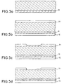
- Figures 5 and 6 respectively illustrate the process steps for making the bottom plate without piezoresistive gauge and the process of the upper plate with piezoresistive gauges.
- FIG. 5 describes the realization of the elements 36, 17, 16 shown in Figure 3a
- the assembly of Figure 6 describes the production of the elements 33, 43, 21, 13 shown in FIG. 3a.
- the upper and lower plates may include thin arms of guidance, ensuring that the movable mass is maintained relative to the fixed frame.
- Figures 4a and 4b illustrate an example configuration in which the upper plate comprises four guide arms 81, 82, 83, 84 (Figure 4a) and the bottom plate also includes four arms guide 85, 86, 87, 88 ( Figure 4b).
- the guide arms may have a thickness close to that of the suspension arms 21 and 22 and be on the one hand located in the upper part of the plate 6 (in the same plane as the suspension arms) and located on the other hand in the part bottom of plate 7.
- a mask is produced by photolithography and etching at the level of layer 91 (FIG. 5c).
- This mask is refined by a second etching step as illustrated in Figure 5d.
- the oxide or nitride layer 91 is then thinned as illustrated in figure 5f.
- a plate silicon in which two insulating layers 93 and 94 have been produced, said plate being also covered on the opposite face with a insulating layer 95.
- the two implanted layers 93 and 94 can be made of several ways.
- Another method is to weld at high temperature two silicon wafers, one of which is oxidized on the surface. We get a set of two silicon wafers assembled at the level of the oxide layer which then constitutes layer 93. One of the platelets can then be machined to define the desired thickness of silicon in which one can carry out an ionic implantation of oxygen to define the layer 94.
- the thin layer 96 makes it possible to define elements of silicon isolated from the rest of the wafers which can constitute gauges piezoelectric better defined and calibrated than those resulting in a way conventional, implantation within a silicon substrate ( Figure 6b).
- the piezoelectric gauges are protected by a layer 97 of nitride for example, or oxide, or both, openings at the layer 97 are locally made to allow connections electrical ( Figure 6c).
- a conductive layer can then be deposited and then etched to form, in known manner, connecting tracks for each gauge, not shown in Figure 6c.
- a mask is produced by etching through layer 95 as illustrated in figure 5d.
- this mask is followed by an etching step chemical of silicon, allowing to define the suspension arm 21, the arm 34 with its stop 43 as well as the upper central part of the mass mobile 13.
- the two silicon plates 6 and 7 thus machined can be welded by heating typically at a temperature of the order of 1000 ° C.
- the two plates can be assembled before carry out the laser cutting illustrated in FIG. 5h which makes it possible to separate the locking arm 17 of the peripheral part of the frame 36, so as to facilitate said assembly.
- the thin guide arms 81, 82, 83, 84 can also be made in the upper plate in the same way as the thin arms of suspension and in the same plane thanks to the etching stop layer.
- the fine guide arms 85, 86, 87, 88 can also be made in the lower plate thanks to the silicon layer included between the oxide layers 90 and 92.
Landscapes
- Physics & Mathematics (AREA)
- General Physics & Mathematics (AREA)
- Electromagnetism (AREA)
- Pressure Sensors (AREA)
Description
- la plaque supérieure comprend :
- la partie supérieure de la masse mobile, comportant une première et une seconde contre-butées le long d'un axe Y défini dans le plan de la masse mobile ;
- la partie supérieure du cadre fixe, comportant une première et une seconde butées le long d'un axe X perpendiculaire à l'axe Y et défini dans le plan de la masse mobile ;
- la partie supérieure de la masse mobile et la partie supérieure du cadre fixe étant reliées par des bras de suspension ;
- la plaque inférieure comprend :
- la partie inférieure de la masse mobile, comportant une troisième et une quatrième contre-butées le long de l'axe X;
- la partie inférieure du cadre fixe, comportant une troisième et une quatrième butées le long de l'axe Y ;
- les première et seconde contre-butées étant respectivement en regard des troisième et quatrième butées ;
- les troisième et quatrième contre-butées étant respectivement en regard des première et second butées.
- la partie supérieure de la masse mobile comprend une première partie centrale et des premier et second bras de blocage situés de part et d'autre de ladite première partie centrale, selon l'axe Y ;
- la partie supérieure du cadre fixe comprend une partie périphérique et des premier et second bras situés à l'intérieur de la partie périphérique, selon l'axe X, la plaque supérieure comprenant des premier et second bras de suspension reliant la partie centrale de la partie supérieure de la masse mobile, aux premier et second bras de la partie périphérique ;
- la partie inférieure de la masse mobile comprend une partie centrale et des troisième et quatrième bras de blocage situés de part et d'autre de ladite seconde partie centrale, selon l'axe X ;
- la partie inférieure du cadre fixe comprend une partie périphérique et des troisième et quatrième bras situés à l'intérieur de la partie périphérique selon l'axe Y ;
- les première et seconde contre-butées étant définies dans les premier et second bras de blocage ;
- les première et seconde butées étant définies dans les premier et second bras ;
- les troisième et quatrième contre-butées étant définies dans les troisième et quatrième bras de blocage ;
- les troisième et quatrième butées étant définies dans les troisième et quatrième bras.
- la figure 1 illustre un accéléromètre selon l'art antérieur ;
- la figure 2a illustre la plaque supérieure utilisée dans un exemple d'accéléromètre selon l'invention ;
- la figure 2b illustre la plaque inférieure utilisée dans un exemple d'accéléromètre selon l'invention ;
- la figure 3a illustre une coupe transversale selon un plan représenté par l'axe AA' de l'ensemble des plaques 6 et 7, représentés sur les figures 2a et 2b ;
- la figure 3b illustre une coupe transversale selon un plan représenté par l'axe BB' de l'ensemble des plaques 6 et 7 représentées sur les figures 2a et 2b ;
- la figure 4a illustre un exemple de plaque 6 avec quatre bras de guidage ;
- la figure 4b illustre un exemple de plaque 7 avec quatre bras de guidage ;
- la figure 5 illustre les étapes de procédé de réalisation d'une plaque inférieure utilisée dans un accéléromètre selon l'invention ;
- la figure 6 illustre les étapes de procédé de réalisation d'une plaque supérieure utilisée dans un accéléromètre selon l'invention.
Claims (6)
- Accéléromètre comprenant une masse mobile (1) reliée à un cadre fixe (3), la masse mobile et le cadre fixe (3) étant définis dans l'empilement de deux plaques de silicium monocristallin dites plaque supérieure (6) et plaque inférieure (7), caractérisé en ce que :la plaque supérieure comprend :la partie supérieure (11) de la masse mobile, comportant une première et une seconde contre-butées (41, 42) le long d'un axe Y défini dans le plan de la masse mobile ;la partie supérieure (31) du cadre fixe, comportant une première et une seconde butées (43, 44) le long d'un axe X perpendiculaire à l'axe Y et défini dans le plan de la masse mobile ;la partie supérieure de la masse mobile (11) et la partie supérieure du cadre fixe (31) étant reliées par des bras de suspension (21, 22);la plaque inférieure comprend :la partie inférieure (12) de la masse mobile, comportant une troisième et une quatrième contre-butées (45, 46) le long de l'axe X;la partie inférieure (32) du cadre fixe, comportant une troisième et une quatrième butées (47, 48) le long de l'axe Y;les première et seconde contre-butées (41, 42) étant respectivement en regard des troisième et quatrième butées (47, 48);les troisième et quatrième contre-butées (45, 46) étant respectivement en regard des première et second butées (43, 44).
- Accéléromètre selon la revendication 1, caractérisé en ce que :la partie supérieure de la masse mobile (11) comprend une première partie centrale (13) et des premier et second bras de blocage (14, 15) situés de part et d'autre de ladite première partie centrale, selon l'axe Y ;la partie supérieure du cadre fixe (31) comprend une partie périphérique (33) et des premier et second bras (34, 35) situés à l'intérieur de la partie périphérique, selon l'axe X, la plaque supérieure (6) comprenant des premier et second bras de suspension (21, 22) reliant la partie centrale de la partie supérieure de la masse mobile, aux premier et second bras de la partie périphérique ;la partie inférieure de la masse mobile (12) comprend une partie centrale (16) et des troisième et quatrième bras de blocage (17, 18) situés de part et d'autre de ladite seconde partie centrale, selon l'axe X ;la partie inférieure du cadre fixe (32) comprend une partie périphérique (36) et des troisième et quatrième bras (37, 38) situés à l'intérieur de la partie périphérique selon l'axe Y ;les première et seconde contre-butées (41, 42) étant définies dans les premier et second bras de blocage (14, 15) ;les première et seconde butées (43, 44) étant définies dans les - premier et second bras (34, 35) ;les troisième et quatrième contre-butées (45, 46) étant définies dans les troisième et quatrième bras de blocage (17, 18) ;les troisième et quatrième butées (47, 48) étant définies dans les troisième et quatrième bras (37, 38).
- Accéléromètre selon la revendication 2, caractérisé en ce que les plaques (6) et (7) comprennent des bras fins de guidage, reliant la masse mobile (1) au cadre fixe (3), lesdits bras étant situés selon deux axes orientés à 45° des axes (X) et (Y).
- Accéléromètre selon la revendication 3, caractérisé en ce que la plaque supérieure (6) comprend quatre bras supérieurs de guidage (81, 82, 83, 84) et que la plaque inférieure (7) comprend quatre bras inférieurs de guidage (85, 86, 87, 88), lesdits bras supérieurs de guidage (81, 82, 83, 84) étant situés au niveau supérieur de la plaque supérieure (6), lesdits bras inférieurs de guidage (85, 86, 87, 88) étant situés au niveau inférieur de la plaque inférieure (7).
- Accéléromètre selon l'une des revendications 2 à 4, caractérisé en ce que les bras de suspension (21) et (22) comprennent des jauges piézorésistives.
- Accéléromètre selon l'une des revendications 1 à 5, caractérisé en ce qu'il comprend un système d'asservissement électromagnétique de la masse mobile (1).
Applications Claiming Priority (3)
| Application Number | Priority Date | Filing Date | Title |
|---|---|---|---|
| FR9514686A FR2742230B1 (fr) | 1995-12-12 | 1995-12-12 | Accelerometre et procede de fabrication |
| FR9514686 | 1995-12-12 | ||
| PCT/FR1996/001968 WO1997022010A1 (fr) | 1995-12-12 | 1996-12-10 | Accelerometre et procede de fabrication |
Publications (2)
| Publication Number | Publication Date |
|---|---|
| EP0866972A1 EP0866972A1 (fr) | 1998-09-30 |
| EP0866972B1 true EP0866972B1 (fr) | 2000-08-02 |
Family
ID=9485396
Family Applications (1)
| Application Number | Title | Priority Date | Filing Date |
|---|---|---|---|
| EP96941729A Expired - Lifetime EP0866972B1 (fr) | 1995-12-12 | 1996-12-10 | Accelerometre et procede de fabrication |
Country Status (10)
| Country | Link |
|---|---|
| US (1) | US6089093A (fr) |
| EP (1) | EP0866972B1 (fr) |
| JP (1) | JP2000502441A (fr) |
| AU (1) | AU706765B2 (fr) |
| BR (1) | BR9612776A (fr) |
| CA (1) | CA2239106A1 (fr) |
| DE (1) | DE69609627D1 (fr) |
| FR (1) | FR2742230B1 (fr) |
| NO (1) | NO982667L (fr) |
| WO (1) | WO1997022010A1 (fr) |
Families Citing this family (14)
| Publication number | Priority date | Publication date | Assignee | Title |
|---|---|---|---|---|
| FR2788163B1 (fr) | 1998-12-30 | 2001-03-16 | Sextant Avionique | Actionneur electromagnetique equipe de moyens d'ajustement de la position de son element polaire mobile |
| GB9912407D0 (en) * | 1999-05-28 | 1999-09-15 | Fisher Tortolano Systems Limit | Navigation apparatus and method |
| US6672168B2 (en) | 2001-09-24 | 2004-01-06 | Andrew Braugh | Multi-level machine vibration tester marker pen |
| JP2003172745A (ja) * | 2001-09-26 | 2003-06-20 | Hitachi Metals Ltd | 半導体加速度センサ |
| US7185542B2 (en) * | 2001-12-06 | 2007-03-06 | Microfabrica Inc. | Complex microdevices and apparatus and methods for fabricating such devices |
| US7372616B2 (en) * | 2001-12-06 | 2008-05-13 | Microfabrica, Inc. | Complex microdevices and apparatus and methods for fabricating such devices |
| US20070121423A1 (en) * | 2001-12-20 | 2007-05-31 | Daniel Rioux | Head-mounted display apparatus for profiling system |
| FR2834055B1 (fr) * | 2001-12-20 | 2004-02-13 | Thales Sa | Capteur inertiel micro-usine pour la mesure de mouvements de rotation |
| CA2366030A1 (fr) | 2001-12-20 | 2003-06-20 | Global E Bang Inc. | Systeme de profilage |
| JP2003232803A (ja) * | 2002-02-12 | 2003-08-22 | Hitachi Metals Ltd | 半導体型加速度センサ |
| FR2838423B1 (fr) * | 2002-04-12 | 2005-06-24 | Thales Sa | Procede de fabrication d'une microstructure comportant une cavite sous vide et microstructure correspondante |
| JP2004198280A (ja) * | 2002-12-19 | 2004-07-15 | Hitachi Metals Ltd | 加速度センサ |
| FR2856789B1 (fr) * | 2003-06-27 | 2005-08-26 | Thales Sa | Gyrometre a masse vibrante |
| KR101454123B1 (ko) * | 2013-08-29 | 2014-10-22 | 삼성전기주식회사 | 가속도 센서 |
Family Cites Families (12)
| Publication number | Priority date | Publication date | Assignee | Title |
|---|---|---|---|---|
| US5000817A (en) * | 1984-10-24 | 1991-03-19 | Aine Harry E | Batch method of making miniature structures assembled in wafer form |
| DE3740688A1 (de) * | 1987-12-01 | 1989-06-15 | Messerschmitt Boelkow Blohm | Mikromechanischer beschleunigungssensor mit hoher achsenselektivitaet |
| US5121633A (en) * | 1987-12-18 | 1992-06-16 | Nissan Motor Co., Ltd. | Semiconductor accelerometer |
| US4882933A (en) * | 1988-06-03 | 1989-11-28 | Novasensor | Accelerometer with integral bidirectional shock protection and controllable viscous damping |
| US5060504A (en) * | 1988-09-23 | 1991-10-29 | Automotive Systems Laboratory, Inc. | Self-calibrating accelerometer |
| US5008774A (en) * | 1989-02-28 | 1991-04-16 | United Technologies Corporation | Capacitive accelerometer with mid-plane proof mass |
| DE4027046A1 (de) * | 1989-09-29 | 1991-04-11 | Siemens Ag | Vorrichtung zum pruefen der funktionsfaehigkeit und/oder eichen eines beschleunigungs-sensors, insbesondere eines aufprall-sensors fuer ein kraftfahrzeug, und verfahren zum betrieb der vorrichtung |
| DE4016472A1 (de) * | 1990-05-22 | 1991-11-28 | Bosch Gmbh Robert | Verfahren zur herstellung von mikromechanischen sensoren mit ueberlastsicherung |
| FR2706634B1 (fr) * | 1993-06-11 | 1995-07-21 | Sextant Avionique | Dispositif optique compact pour la vision nocturne et son application à des lunettes. |
| US5503285A (en) * | 1993-07-26 | 1996-04-02 | Litton Systems, Inc. | Method for forming an electrostatically force balanced silicon accelerometer |
| FR2713449B1 (fr) * | 1993-12-10 | 1996-01-05 | Sextant Avionique | Visière d'équipement de tête à transmission variable. |
| KR0139506B1 (ko) * | 1994-10-07 | 1998-07-15 | 전성원 | 자체진단 기능을 구비한 대칭질량형 가속도계 및 그 제조방법 |
-
1995
- 1995-12-12 FR FR9514686A patent/FR2742230B1/fr not_active Expired - Fee Related
-
1996
- 1996-12-10 EP EP96941729A patent/EP0866972B1/fr not_active Expired - Lifetime
- 1996-12-10 US US09/077,888 patent/US6089093A/en not_active Expired - Fee Related
- 1996-12-10 WO PCT/FR1996/001968 patent/WO1997022010A1/fr not_active Ceased
- 1996-12-10 DE DE69609627T patent/DE69609627D1/de not_active Expired - Lifetime
- 1996-12-10 JP JP9521794A patent/JP2000502441A/ja active Pending
- 1996-12-10 BR BR9612776-7A patent/BR9612776A/pt not_active Application Discontinuation
- 1996-12-10 AU AU11015/97A patent/AU706765B2/en not_active Ceased
- 1996-12-10 CA CA002239106A patent/CA2239106A1/fr not_active Abandoned
-
1998
- 1998-06-10 NO NO982667A patent/NO982667L/no not_active Application Discontinuation
Also Published As
| Publication number | Publication date |
|---|---|
| NO982667L (no) | 1998-08-11 |
| WO1997022010A1 (fr) | 1997-06-19 |
| DE69609627D1 (de) | 2000-09-07 |
| EP0866972A1 (fr) | 1998-09-30 |
| NO982667D0 (no) | 1998-06-10 |
| CA2239106A1 (fr) | 1997-06-19 |
| FR2742230B1 (fr) | 1998-01-09 |
| JP2000502441A (ja) | 2000-02-29 |
| AU1101597A (en) | 1997-07-03 |
| FR2742230A1 (fr) | 1997-06-13 |
| AU706765B2 (en) | 1999-06-24 |
| US6089093A (en) | 2000-07-18 |
| BR9612776A (pt) | 2001-01-02 |
Similar Documents
| Publication | Publication Date | Title |
|---|---|---|
| EP0557217B1 (fr) | Micro-capteur capacitif à faible capacité parasite et procédé de fabrication | |
| EP2038929B1 (fr) | Procédé pour la réalisation d'une matrice de composants électroniques individuels et matrice réalisée par ce procédé | |
| EP0605300B1 (fr) | Procédé de fabrication d'accéléromètres utilisant la technologie silicium sur isolant | |
| EP0596456B1 (fr) | Procédé de fabrication de transducteurs capacitifs intégrés | |
| EP0923130B1 (fr) | Circuit électronique, notamment pour un dispositif médical implantable actif tel qu'un stimulateur ou défibrillateur cardiaque, et son procédé de réalisation | |
| WO1997022010A1 (fr) | Accelerometre et procede de fabrication | |
| EP0798548B1 (fr) | Capteur à jauge de contrainte utilisant l'effet piézorésistif et son procédé de fabrication | |
| EP0605302A2 (fr) | Procédé de fabrication d'un capteur de pression utilisant la technologie silicium sur isolant et capteur obtenu | |
| EP1027583B1 (fr) | Structure munie de contacts electriques formes a travers le substrat de cette structure et procede d'obtention d'une telle structure | |
| EP0165085A1 (fr) | Procédé de réalisation de contacts d'aluminium à travers une couche isolante épaisse dans un circuit intégré | |
| EP0983609B1 (fr) | Procede de fabrication d'un micro-capteur en silicium usine | |
| EP0557219B1 (fr) | Micro-capteur capacitif à capacité parasite réduite et procédé de fabrication | |
| EP1133683B1 (fr) | Capteur de pression a membrane comportant du carbure de silicium et procede de fabrication | |
| EP1700343A1 (fr) | Procede de fabrication de puces electroniques en silicium aminci | |
| EP3633336A1 (fr) | Dispositif de detection pyroelectrique a membrane rigide | |
| EP1133684B1 (fr) | Structure micro-usinee a membrane deformable et son procede de realisation | |
| EP1433203B1 (fr) | Procédé de réalisation d'une prise de contact en face arriere d'un composant à substrats empiles | |
| FR2738705A1 (fr) | Dispositif capteur electromecanique et procede de fabrication d'un tel dispositif | |
| FR3037720A1 (fr) | Composant electronique et son procede de fabrication | |
| EP0611221A1 (fr) | Micro-capteur capacitif à faible capacité parasite et procédé de fabrication | |
| EP3551574B1 (fr) | Réduction de capacités parasites dans un dispositif microélectronique | |
| EP3886159A1 (fr) | Puce d'interconnexion | |
| FR2938974A1 (fr) | Composant microelectromecanique et procede de fabrication |
Legal Events
| Date | Code | Title | Description |
|---|---|---|---|
| PUAI | Public reference made under article 153(3) epc to a published international application that has entered the european phase |
Free format text: ORIGINAL CODE: 0009012 |
|
| 17P | Request for examination filed |
Effective date: 19980529 |
|
| AK | Designated contracting states |
Kind code of ref document: A1 Designated state(s): CH DE DK FI GB LI NL SE |
|
| GRAG | Despatch of communication of intention to grant |
Free format text: ORIGINAL CODE: EPIDOS AGRA |
|
| RAP1 | Party data changed (applicant data changed or rights of an application transferred) |
Owner name: THOMSON-CSF SEXTANT |
|
| 17Q | First examination report despatched |
Effective date: 19991007 |
|
| GRAG | Despatch of communication of intention to grant |
Free format text: ORIGINAL CODE: EPIDOS AGRA |
|
| GRAG | Despatch of communication of intention to grant |
Free format text: ORIGINAL CODE: EPIDOS AGRA |
|
| GRAH | Despatch of communication of intention to grant a patent |
Free format text: ORIGINAL CODE: EPIDOS IGRA |
|
| GRAH | Despatch of communication of intention to grant a patent |
Free format text: ORIGINAL CODE: EPIDOS IGRA |
|
| GRAA | (expected) grant |
Free format text: ORIGINAL CODE: 0009210 |
|
| AK | Designated contracting states |
Kind code of ref document: B1 Designated state(s): CH DE DK FI GB LI NL SE |
|
| PG25 | Lapsed in a contracting state [announced via postgrant information from national office to epo] |
Ref country code: NL Free format text: LAPSE BECAUSE OF FAILURE TO SUBMIT A TRANSLATION OF THE DESCRIPTION OR TO PAY THE FEE WITHIN THE PRESCRIBED TIME-LIMIT Effective date: 20000802 |
|
| REG | Reference to a national code |
Ref country code: CH Ref legal event code: EP |
|
| REF | Corresponds to: |
Ref document number: 69609627 Country of ref document: DE Date of ref document: 20000907 |
|
| GBT | Gb: translation of ep patent filed (gb section 77(6)(a)/1977) |
Effective date: 20001004 |
|
| PG25 | Lapsed in a contracting state [announced via postgrant information from national office to epo] |
Ref country code: DK Free format text: LAPSE BECAUSE OF FAILURE TO SUBMIT A TRANSLATION OF THE DESCRIPTION OR TO PAY THE FEE WITHIN THE PRESCRIBED TIME-LIMIT Effective date: 20001102 |
|
| PG25 | Lapsed in a contracting state [announced via postgrant information from national office to epo] |
Ref country code: DE Free format text: LAPSE BECAUSE OF FAILURE TO SUBMIT A TRANSLATION OF THE DESCRIPTION OR TO PAY THE FEE WITHIN THE PRESCRIBED TIME-LIMIT Effective date: 20001103 |
|
| NLV1 | Nl: lapsed or annulled due to failure to fulfill the requirements of art. 29p and 29m of the patents act | ||
| PLBE | No opposition filed within time limit |
Free format text: ORIGINAL CODE: 0009261 |
|
| STAA | Information on the status of an ep patent application or granted ep patent |
Free format text: STATUS: NO OPPOSITION FILED WITHIN TIME LIMIT |
|
| 26N | No opposition filed | ||
| REG | Reference to a national code |
Ref country code: GB Ref legal event code: IF02 |
|
| PGFP | Annual fee paid to national office [announced via postgrant information from national office to epo] |
Ref country code: SE Payment date: 20031204 Year of fee payment: 8 |
|
| PGFP | Annual fee paid to national office [announced via postgrant information from national office to epo] |
Ref country code: GB Payment date: 20031210 Year of fee payment: 8 |
|
| PGFP | Annual fee paid to national office [announced via postgrant information from national office to epo] |
Ref country code: FI Payment date: 20031212 Year of fee payment: 8 |
|
| PGFP | Annual fee paid to national office [announced via postgrant information from national office to epo] |
Ref country code: CH Payment date: 20031223 Year of fee payment: 8 |
|
| PG25 | Lapsed in a contracting state [announced via postgrant information from national office to epo] |
Ref country code: FI Free format text: LAPSE BECAUSE OF NON-PAYMENT OF DUE FEES Effective date: 20041204 |
|
| PG25 | Lapsed in a contracting state [announced via postgrant information from national office to epo] |
Ref country code: GB Free format text: LAPSE BECAUSE OF NON-PAYMENT OF DUE FEES Effective date: 20041210 |
|
| PG25 | Lapsed in a contracting state [announced via postgrant information from national office to epo] |
Ref country code: SE Free format text: LAPSE BECAUSE OF NON-PAYMENT OF DUE FEES Effective date: 20041211 |
|
| PG25 | Lapsed in a contracting state [announced via postgrant information from national office to epo] |
Ref country code: LI Free format text: LAPSE BECAUSE OF NON-PAYMENT OF DUE FEES Effective date: 20041231 Ref country code: CH Free format text: LAPSE BECAUSE OF NON-PAYMENT OF DUE FEES Effective date: 20041231 |
|
| EUG | Se: european patent has lapsed | ||
| GBPC | Gb: european patent ceased through non-payment of renewal fee |
Effective date: 20041210 |
|
| REG | Reference to a national code |
Ref country code: CH Ref legal event code: PL |