EP0866178A2 - Schaufel für einen Bagger - Google Patents
Schaufel für einen Bagger Download PDFInfo
- Publication number
- EP0866178A2 EP0866178A2 EP98104032A EP98104032A EP0866178A2 EP 0866178 A2 EP0866178 A2 EP 0866178A2 EP 98104032 A EP98104032 A EP 98104032A EP 98104032 A EP98104032 A EP 98104032A EP 0866178 A2 EP0866178 A2 EP 0866178A2
- Authority
- EP
- European Patent Office
- Prior art keywords
- excavation
- bucket
- fittings
- tooth
- ground
- Prior art date
- Legal status (The legal status is an assumption and is not a legal conclusion. Google has not performed a legal analysis and makes no representation as to the accuracy of the status listed.)
- Withdrawn
Links
Images


Classifications
-
- E—FIXED CONSTRUCTIONS
- E02—HYDRAULIC ENGINEERING; FOUNDATIONS; SOIL SHIFTING
- E02F—DREDGING; SOIL-SHIFTING
- E02F9/00—Component parts of dredgers or soil-shifting machines, not restricted to one of the kinds covered by groups E02F3/00 - E02F7/00
- E02F9/28—Small metalwork for digging elements, e.g. teeth scraper bits
- E02F9/2808—Teeth
- E02F9/2858—Teeth characterised by shape
-
- E—FIXED CONSTRUCTIONS
- E02—HYDRAULIC ENGINEERING; FOUNDATIONS; SOIL SHIFTING
- E02F—DREDGING; SOIL-SHIFTING
- E02F3/00—Dredgers; Soil-shifting machines
- E02F3/04—Dredgers; Soil-shifting machines mechanically-driven
- E02F3/28—Dredgers; Soil-shifting machines mechanically-driven with digging tools mounted on a dipper- or bucket-arm, i.e. there is either one arm or a pair of arms, e.g. dippers, buckets
- E02F3/36—Component parts
- E02F3/40—Dippers; Buckets ; Grab devices, e.g. manufacturing processes for buckets, form, geometry or material of buckets
-
- E—FIXED CONSTRUCTIONS
- E02—HYDRAULIC ENGINEERING; FOUNDATIONS; SOIL SHIFTING
- E02F—DREDGING; SOIL-SHIFTING
- E02F9/00—Component parts of dredgers or soil-shifting machines, not restricted to one of the kinds covered by groups E02F3/00 - E02F7/00
- E02F9/28—Small metalwork for digging elements, e.g. teeth scraper bits
- E02F9/2808—Teeth
- E02F9/2816—Mountings therefor
- E02F9/2825—Mountings therefor using adapters
-
- E—FIXED CONSTRUCTIONS
- E02—HYDRAULIC ENGINEERING; FOUNDATIONS; SOIL SHIFTING
- E02F—DREDGING; SOIL-SHIFTING
- E02F9/00—Component parts of dredgers or soil-shifting machines, not restricted to one of the kinds covered by groups E02F3/00 - E02F7/00
- E02F9/28—Small metalwork for digging elements, e.g. teeth scraper bits
- E02F9/2808—Teeth
- E02F9/2816—Mountings therefor
- E02F9/2833—Retaining means, e.g. pins
-
- Y—GENERAL TAGGING OF NEW TECHNOLOGICAL DEVELOPMENTS; GENERAL TAGGING OF CROSS-SECTIONAL TECHNOLOGIES SPANNING OVER SEVERAL SECTIONS OF THE IPC; TECHNICAL SUBJECTS COVERED BY FORMER USPC CROSS-REFERENCE ART COLLECTIONS [XRACs] AND DIGESTS
- Y10—TECHNICAL SUBJECTS COVERED BY FORMER USPC
- Y10S—TECHNICAL SUBJECTS COVERED BY FORMER USPC CROSS-REFERENCE ART COLLECTIONS [XRACs] AND DIGESTS
- Y10S37/00—Excavating
- Y10S37/903—Scoop or scraper attachments
Definitions
- the present invention relates to a bucket tool for a power shovel that can be used for the excavation operation as well as for the ground-leveling operation.
- a power shovel 1 used for the construction work is equipped with a boom 2 that can be raised and lowered, and wherein a base end of an arm 3 is pivoted to an end of the boom 2, and a base portion of a bucket 4 is pivoted to another end of the arm 3.
- the front part of the bucket 4 is provided with a plurality of protruding excavation teeth 5 in an interval like a fork.
- the power shovel 1 is horizontally turned to change the direction of the boom 2, the boom 2 is raised and lowered, and the arm 3 and the bucket 4 are turned, in order to excavate the sand, soil, gravel, rock, etc.
- the excavated sand, soil, etc. are scooped up by the bucket 4 and are loaded onto a dump truck, etc.
- the ground is usually leveled by any one of the following three methods.
- each power shovel 1 When the ground is leveled by replacing the bucket by the leveling bucket without the excavation teeth 5 of (1), however, each power shovel 1 must be provided with both the excavation bucket 4 and the ground-leveling bucket, accompanied by an increase in the cost and a cumbersome operation for replacing the bucket on the site.
- the steel plate must be welded on the site which is cumbersome.
- the steel plate once welded onto the excavation teeth 5 must be removed involving a cumbersome operation.
- the split teeth are not flatly overlapped but are ruggedly overlapped by each other. Therefore, the ground is not flatly leveled, which is not suited for the leveling operation where flatness is required. Besides, since the split teeth are broad, an increased load is exerted on each split tooth, and the portions where the split teeth are mounted on the excavation teeth 5 cannot withstand the use for extended periods of time.
- the object of the present invention is to provide a bucket tool for a power shovel which enables a ground-leveling plate to be easily and detachably attached to the excavation teeth of the excavation bucket, so that both the excavation operation and the ground-leveling operation can be performed without being accompanied by cumbersome operation, precluding the above-mentioned defects inherent in the prior art.
- the present invention is concerned with a bucket tool for a power shovel comprising an edge secured to a front part of the bottom plate of a bucket at the lower part of the bucket in a lateral direction, tooth-mounting fittings secured to the edge with an interval between the adjacent fittings in the lateral direction, excavation teeth detachably mounted on the tooth-mounting fittings and protruding forward beyond the edge, a ground-leveling plate having a lateral width equal to the lateral width of the lower part of the bucket, and coupling fittings secured to the upper surface of the ground-leveling plate with an interval nearly equal to the interval for securing the tooth-mounting fittings and capable of being attachably/detachably mounted on the ends of the excavation teeth, enabling the ground-leveling plate to be easily attached to, or detached from, the ends of the excavation teeth via coupling fittings.
- the above-mentioned bucket tool for a power shovel of the present invention further includes excavation tooth holes perforated through the ends of the excavation teeth, coupling fitting elongated holes perforated in the coupling fittings and elongated in the lateral direction of the bucket, pins inserted in the excavation tooth holes and in the coupling fitting elongated holes to couple the excavation teeth and the coupling fittings together, and stop rings interposed between the excavation teeth and the coupling fittings and mounted to surround the pins, enabling the ground-leveling plate to be mounted without any trouble despite the positions of the excavation teeth and the positions of the coupling fittings of the ground-leveling plate being not in agreement in the lateral direction.
- the bucket tool for a power shovel may further include spacers interposed together with the stop rings between the excavation teeth and the coupling fittings, enabling the ground-leveling plate to be mounted without any trouble despite the positions of the excavation teeth being not uniform in the up-and-down direction.
- Fig. 1 is a plan view illustrating a major portion of an embodiment of the present invention.
- Fig. 2 is a vertical side view taken along the line II-II in Fig. 1.
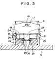
- Fig. 3 is a vertical front view taken along the line III-III in Fig. 2.
- Fig. 4 is a perspective view illustrating the embodiment of the present invention.
- Fig. 5 is a side view of a conventional bucket of a power shovel.
- Fig. 4 is a perspective view illustrating an embodiment of the present invention, wherein side shrouds 6 are secured to both sides of the bucket 4 near the lower portions thereof in the vertical direction, and an edge 7 is secured to a front part of the bottom plate of the bucket 4 in the lateral direction.
- a plurality of tooth-mounting fittings 8 are secured to the front part of the edge 7 nearly with a predetermined interval in the lateral direction.
- the tooth-mounting fittings 8 are formed solid having a rectangular shape in transverse cross section and extending forward. Onto the tooth-mounting fittings 8 can be detachably mounted excavation teeth 9 in a manner as described below. Onto the excavation teeth 9 is further attachably/detachably mounted a ground-leveling plate 10 having a lateral width equal to the lateral width of the lower part of the bucket 4 via coupling fittings 11.
- Fig. 1 is a plan view illustrating, on an enlarged scale, a major portion equipped with the above-mentioned tooth-mounting fittings 8, the excavation teeth 9, the ground-leveling plate 10 and the coupling fittings 11 according to an embodiment of the present invention
- Fig. 2 is a vertical side view taken along the line II-II in Fig. 1
- Fig. 3 is a vertical plan view taken along the line III-III in Figs. 1 and 2, and wherein, as shown in Fig.
- the tooth-mounting fittings 8 secured by welding 12 to the front part of the edge 7 are protruding beyond the front part of the edge 7, and a hole 13 is perforated in the up-and-down direction in the end of the tooth-mounting fittings 8 as shown in Fig. 2.
- the excavation tooth 9 attachably/detachably mounted on the end of the tooth-mounting fitting 8 has a fitting opening 14 which is opened rearward as shown in Figs. 1 and 2, and a hole 15 is perforated in a rear upper part of the fitting opening 14 as shown in Fig. 2.
- a plug 16 is inserted in the hole 13 in the tooth-mounting fitting 8 and, then, the fitting opening 14 in the excavation tooth 9 is fitted to the end of the tooth-mounting fitting 8.
- a pin 17 is inserted in the hole 15 in the excavation tooth 9.
- the excavation tooth 9 is secured to the tooth-mounting fitting 8 in a state of being mounted on the end of the tooth-mounting fitting 8. Upon removing the pin 17 toward the upper side or the lower side of the hole 15, it is allowed to remove the excavation tooth 9 from the tooth-mounting fitting 8.
- a low flat portion 18 is formed in the end of the excavation tooth 9 over the whole lateral width of the excavation tooth 9.
- a hole 19 for inserting a pin 27 is formed in the center of the flat portion 18, and a stepped portion 20 is formed at the upper peripheral edge thereof as shown in Figs. 2 and 3.
- the ground-leveling plate 10 is positioned on the lower surfaces of the excavation teeth 9 as shown in Figs. 1 to 3, the ground-leveling plate 10 having a lateral width equal to the lateral width of the lower part of the bucket 4 as described with reference to Fig. 4, and having the coupling fittings 11 secured onto the upper surface thereof by welding 21 (see Figs. 1 and 2).
- the coupling fitting 11 has a rear part that extends like a cover and has an opening 22 formed in the rear lower surface thereof and over the whole lateral width thereof. In the opening 22 is inserted the flat portion 18 formed in the end of the excavation tooth 9.
- an elongated hole 23 extending in the direction of width of the coupling fitting 11 as shown in Figs. 2 and 3, and a stepped portion 24 is formed at an upper peripheral edge thereof.
- a stop ring 25 of the shape of a spring washer is placed on the stepped portion 20 in the end of the excavation tooth 9, the flat portion 18 of the excavation tooth 9 is inserted in the opening 22 in the rear part of the coupling fitting 11, and a pin 27 having a groove 26 formed in the circumference thereof at an intermediate portion is inserted through the coupling fitting elongated hole 23, the stop ring 25 and the insertion hole 19. Then, the stop ring 25 is fitted to the groove 26 of the pin 27; i.e., the pin 27 is prevented from escaping.
- the coupling fitting 11 is mounted on the end of the excavation tooth 9, and the ground-leveling plate 10 that is secured by the welding 21 to the lower surface of the coupling fitting 11, is secured to the lower side of the excavation tooth 9 as shown in Fig. 4, so that the ground can be leveled.
- a spacer 28 of a suitable thickness in the form of a washer is placed on the stop ring 25 of the form of a spring washer that is placed on the stepped portion 20 in the end of the excavation tooth 9, and the pin 27 is inserted in the coupling fitting elongated hole 23, the spacer 28, the stop ring 25 and the insertion hole 19.
- the stop ring 25 comes into close contact with the bottom surface of the stepped portion 20 in the end of the excavation tooth 9, and the spacer 28 comes into close contact with the lower surface of the rear portion of the coupling fitting 11 that is extending like a cover, and no play is produced between the excavation tooth 9 and the coupling fitting 11.
- the plurality of the tooth-mounting fittings 8 secured to the front part of the edge 7 may have a mounting pitch that differs in the lateral direction depending upon the manufacturers.
- the central positions of the excavation teeth 9 in the lateral direction mounted on the ends of the tooth-mounting fittings 8 may not be in correct agreement with the central positions of the coupling fittings 11 in the lateral direction.
- the openings 22 in the coupling fittings 11 are extending over the full lateral length of the coupling fittings 11 to absorb differences in the pitches in the products of various manufacturers. Therefore, the flat portion 18 of the excavation tooth 9 can be inserted in the opening 22 in the rear portion of the coupling fitting 11 without any trouble.
- the coupling fitting elongated holes 23 have been lengthened in the lateral direction, the pins 27 can be inserted in the coupling fitting elongated holes 23 and in the insertion holes 19 without any trouble.
- the positions of the plurality of the tooth-mounting fittings 8 may become irregular in the up-and-down direction.
- the flat portions 18 of the excavation teeth 9 can be inserted in the openings 22 in the rear portions of the coupling fittings 11 without any trouble despite the positions of the ends of the excavation teeth 9 being not uniform in the up-and-down direction due to irregular positions of the tooth-mounting fittings 8 in the up-and-down direction. No play develops among the excavation teeth 9, coupling fittings 11 and ground-leveling plate 10.
- the excavation teeth 9 in the excavation state can be replaced by other excavation teeth 9 having different shapes and sizes by pulling the pins 17 shown in Fig. 2 toward the upper side or the lower side of the holes 15.
- the excavation operation and the ground-leveling operation can be alternately executed by the power shovel which is not provided with a bucket exclusively for leveling the ground.
- the ground-leveling plate having coupling fittings needs be provided offering merits of decreased cost, easy transportation of the machine, and easy mounting/removing operation on the site.
- the invention is suited for the ground-leveling operation where it is required to highly flatten the ground.
- the ground-leveling plate can be mounted without any trouble despite the plurality of the tooth-mounting fittings being secured to the front part of the bottom plate of the bucket at dissimilar pitches in the lateral direction or despite the coupling fittings 11 being secured to the upper surface of the ground-leveling plate 10 at dissimilar pitches in the lateral direction.
- the ground-leveling plate is mounted without any trouble despite the plurality of tooth-mounting fittings being located at irregular positions in the up-and-down direction, and without producing play among the excavation teeth, coupling fittings and ground-leveling plate.
Landscapes
- Engineering & Computer Science (AREA)
- Mining & Mineral Resources (AREA)
- Civil Engineering (AREA)
- General Engineering & Computer Science (AREA)
- Structural Engineering (AREA)
- Mechanical Engineering (AREA)
- Shovels (AREA)
- Component Parts Of Construction Machinery (AREA)
Applications Claiming Priority (2)
| Application Number | Priority Date | Filing Date | Title |
|---|---|---|---|
| JP9064574A JPH10259620A (ja) | 1997-03-18 | 1997-03-18 | パワーショベルのバケット工具 |
| JP64574/97 | 1997-03-18 |
Publications (2)
| Publication Number | Publication Date |
|---|---|
| EP0866178A2 true EP0866178A2 (de) | 1998-09-23 |
| EP0866178A3 EP0866178A3 (de) | 1999-03-03 |
Family
ID=13262149
Family Applications (1)
| Application Number | Title | Priority Date | Filing Date |
|---|---|---|---|
| EP98104032A Withdrawn EP0866178A3 (de) | 1997-03-18 | 1998-03-06 | Schaufel für einen Bagger |
Country Status (3)
| Country | Link |
|---|---|
| US (1) | US6070345A (de) |
| EP (1) | EP0866178A3 (de) |
| JP (1) | JPH10259620A (de) |
Cited By (1)
| Publication number | Priority date | Publication date | Assignee | Title |
|---|---|---|---|---|
| WO2003093587A1 (en) * | 2002-05-06 | 2003-11-13 | Dura-Tuff Wear Products, Llc | Scraper blade attachable to the bucket of earth moving equipment |
Families Citing this family (29)
| Publication number | Priority date | Publication date | Assignee | Title |
|---|---|---|---|---|
| US6243975B1 (en) * | 1999-05-20 | 2001-06-12 | Jeffrey Gall | Blade attachment for excavator bucket |
| US6751897B2 (en) * | 2000-11-27 | 2004-06-22 | Robert S. Bierwith | Lip assembly |
| US6457268B1 (en) * | 2000-12-22 | 2002-10-01 | Caterpillar Inc | Edge protection assembly for an implement of a work machine |
| US6526678B2 (en) * | 2001-03-07 | 2003-03-04 | John Albert Waddington, Jr. | Demo-dozer |
| US6860044B2 (en) * | 2003-03-17 | 2005-03-01 | Darwin Robert Keiper | Quick attachable blade |
| US7114272B2 (en) * | 2003-09-09 | 2006-10-03 | H&L Tooth Company | Winged digging tooth |
| USD527029S1 (en) | 2004-06-14 | 2006-08-22 | H&L Tooth Company | Ground engaging tooth |
| US7992328B2 (en) | 2005-03-30 | 2011-08-09 | Striegel Monte G | Trench wall ripper apparatus |
| US7712234B2 (en) * | 2005-03-30 | 2010-05-11 | Striegel Monte G | Trench wall ripper apparatus |
| USD524826S1 (en) * | 2005-07-06 | 2006-07-11 | Caterpillar Inc. | Bucket |
| USD551684S1 (en) | 2006-06-29 | 2007-09-25 | Caterpillar Inc | Excavator bucket |
| US7581340B2 (en) * | 2007-10-08 | 2009-09-01 | Brian John Wolfe | Scraper blade attachment for toothed buckets of earth working machines |
| USD656522S1 (en) * | 2008-02-21 | 2012-03-27 | Amulet Manufacturing Company | Excavator bucket |
| DE202009002635U1 (de) * | 2008-12-05 | 2010-04-29 | Liebherr-Hydraulikbagger Gmbh | Wechselbare Schneide für Tieflöffel |
| USD616469S1 (en) * | 2009-09-18 | 2010-05-25 | Werk-Brau Co. Inc. | Bucket |
| CA2789773C (en) * | 2010-02-15 | 2019-01-15 | Cutting Edges Equipment Parts Pty Limited | A wear assembly and lock mechanism |
| USD702738S1 (en) * | 2011-07-01 | 2014-04-15 | Timothy M. Molnar | Attachment for equipment bucket |
| AU339154S (en) * | 2011-09-27 | 2011-10-25 | Bradken Resources Pty Ltd | Excavation bucket |
| AU339549S (en) * | 2011-09-27 | 2011-11-22 | Bradken Resources Pty Ltd | Shroud for excavation bucket |
| AU339548S (en) * | 2011-09-27 | 2011-11-22 | Bradken Resources Pty Ltd | Shroud for excavation bucket |
| AU339116S (en) * | 2011-09-27 | 2011-10-24 | Bradken Resources Pty Ltd | Cheek plate for excavation bucket |
| AU339153S (en) * | 2011-09-27 | 2011-10-25 | Bradken Resources Pty Ltd | Excavation bucket corner element |
| US20130164106A1 (en) * | 2011-12-21 | 2013-06-27 | Caterpillar Sarl | Attachment for a bucket |
| JP5318993B1 (ja) * | 2012-05-29 | 2013-10-16 | 株式会社小松製作所 | 建設機械の掘削バケット |
| KR20180072712A (ko) * | 2015-09-28 | 2018-06-29 | 프란츠 카세커 게엠베하 | 정확하게 맞춰지는 부착 블레이드 및 대응하는 굴착기 스쿠프를 제작하기 위한 시스템 및 방법 |
| US20170314227A1 (en) * | 2016-04-27 | 2017-11-02 | Custom Grading, Inc. | Method for Conversion of Earth-Working Bucket and Attachment Therefor |
| US10689826B1 (en) * | 2018-08-29 | 2020-06-23 | Brandon Hardin | Digging bar attachment for toothed bucket |
| USD930051S1 (en) * | 2020-06-15 | 2021-09-07 | Sega Ag Group, LLC | Excavator bucket |
| DK181255B1 (en) * | 2022-01-21 | 2023-06-08 | Jacob Soerensen Toettrup | Tool for removing gravel |
Family Cites Families (12)
| Publication number | Priority date | Publication date | Assignee | Title |
|---|---|---|---|---|
| US3469330A (en) * | 1967-10-27 | 1969-09-30 | John W Hood | Backhoe and auxiliary blade therefor |
| CH527977A (de) * | 1970-06-09 | 1972-09-15 | Zepf Hans Rudolf | Schaufelzahn an einer Schaufel einer Baumaschine |
| US3765109A (en) * | 1972-03-17 | 1973-10-16 | Myers Excavating Ltd | Scraping blade for converting a cutting edge on a loading bucket |
| US3942271A (en) * | 1974-07-08 | 1976-03-09 | Anthony Joseph George | Backhoe attachment |
| US4009529A (en) * | 1975-09-25 | 1977-03-01 | Johnson Lawrence M | Grading blade for a toothed shovel |
| US4043060A (en) * | 1976-08-30 | 1977-08-23 | Caterpillar Tractor Co. | Combination strengthened loader bucket and replaceable cutting edge |
| US4208815A (en) * | 1978-06-09 | 1980-06-24 | Julius Ralph Yunker | Straight edge blade for installation on an earth moving bucket |
| US5253449A (en) * | 1992-09-28 | 1993-10-19 | Webb Kenneth W | Detachable finishing blade for excavating bucket |
| US5596825A (en) * | 1994-11-29 | 1997-01-28 | Von Schalscha; Craig C. | Excavation bucket grading attachment |
| JP2935094B2 (ja) * | 1995-09-12 | 1999-08-16 | 牛久産機有限会社 | 爪ホルダー |
| JPH09137477A (ja) * | 1995-11-15 | 1997-05-27 | Juki Buhin Kk | パワーショベル等のバケットの地均し板 |
| US5918389A (en) * | 1998-01-22 | 1999-07-06 | Hall's Dirt Squeege Blade, Inc. | Scraper blade for toothed buckets of earth working machines |
-
1997
- 1997-03-18 JP JP9064574A patent/JPH10259620A/ja not_active Withdrawn
-
1998
- 1998-03-05 US US09/035,470 patent/US6070345A/en not_active Expired - Fee Related
- 1998-03-06 EP EP98104032A patent/EP0866178A3/de not_active Withdrawn
Cited By (2)
| Publication number | Priority date | Publication date | Assignee | Title |
|---|---|---|---|---|
| WO2003093587A1 (en) * | 2002-05-06 | 2003-11-13 | Dura-Tuff Wear Products, Llc | Scraper blade attachable to the bucket of earth moving equipment |
| US6810610B2 (en) | 2002-05-06 | 2004-11-02 | Dura-Tuff Wear Products, L.L.C. | Edge attachment for the bucket of earth moving equipment |
Also Published As
| Publication number | Publication date |
|---|---|
| US6070345A (en) | 2000-06-06 |
| JPH10259620A (ja) | 1998-09-29 |
| EP0866178A3 (de) | 1999-03-03 |
Similar Documents
| Publication | Publication Date | Title |
|---|---|---|
| US6070345A (en) | Bucket tool for a power shovel | |
| US6952892B1 (en) | Lip assembly | |
| US6834447B1 (en) | Excavator sizing bucket | |
| US4058173A (en) | Blade assembly with replaceable cutting edge | |
| US4282665A (en) | Excavator tooth assembly | |
| US4038766A (en) | Excavator bucket ripper tool | |
| US6360458B2 (en) | Rake attachment for skid steer loaders and front end loaders and method for converting a loader bucket into a lawn preparation tool | |
| AU2005201272B2 (en) | Lip assembly including side portions with projections | |
| CN108625427B (zh) | 用于具有对称斗齿安装构件的机具系统的铲斗 | |
| JP2005090052A (ja) | バケット | |
| JP3479489B2 (ja) | 掘削用機械のバケット体に付設される刃体 | |
| CN210177564U (zh) | 挖掘机平面挖掘装置 | |
| JP2942955B1 (ja) | 建設機械のフォーク型アタッチメント及び建設機械のバケット型アタッチメント。 | |
| JPH09137477A (ja) | パワーショベル等のバケットの地均し板 | |
| CA1069960A (en) | Excavating tooth | |
| JP4494157B2 (ja) | 親杭横矢板による土留工法及びメッセル鋼板 | |
| JPH11148149A (ja) | パワーショベル等のバケット本体に付設する地均板部材 | |
| US20030066664A1 (en) | Ripper assembly | |
| JP2001040692A (ja) | 断面形状くの字型のカッティングエッジを装着した地均し作業を行う建設機械のブレードの構造 | |
| JP2878632B2 (ja) | 土木建設機械のパワーショベルにおけるバケット工具 | |
| JPH1077664A (ja) | 掘削機用平爪プレート | |
| JPH11293716A (ja) | パワーショベルのバケット工具 | |
| KR200362690Y1 (ko) | 굴삭기용 버킷의 평삭투스포인트 | |
| JP7525966B1 (ja) | クランプ | |
| JP2001040693A (ja) | 掘削作業機のブレード構造 |
Legal Events
| Date | Code | Title | Description |
|---|---|---|---|
| PUAI | Public reference made under article 153(3) epc to a published international application that has entered the european phase |
Free format text: ORIGINAL CODE: 0009012 |
|
| 17P | Request for examination filed |
Effective date: 19980306 |
|
| AK | Designated contracting states |
Kind code of ref document: A2 Designated state(s): BE DE ES FR GB IT NL |
|
| AX | Request for extension of the european patent |
Free format text: AL;LT;LV;MK;RO;SI |
|
| PUAL | Search report despatched |
Free format text: ORIGINAL CODE: 0009013 |
|
| AK | Designated contracting states |
Kind code of ref document: A3 Designated state(s): AT BE CH DE DK ES FI FR GB GR IE IT LI LU MC NL PT SE |
|
| AX | Request for extension of the european patent |
Free format text: AL;LT;LV;MK;RO;SI |
|
| AKX | Designation fees paid |
Free format text: BE DE ES FR GB IT NL |
|
| 17Q | First examination report despatched |
Effective date: 20020510 |
|
| GRAH | Despatch of communication of intention to grant a patent |
Free format text: ORIGINAL CODE: EPIDOS IGRA |
|
| STAA | Information on the status of an ep patent application or granted ep patent |
Free format text: STATUS: THE APPLICATION HAS BEEN WITHDRAWN |
|
| 18W | Application withdrawn |
Effective date: 20030102 |