EP0865409B1 - Schutz- und transportvorrichtung für reitsättel - Google Patents
Schutz- und transportvorrichtung für reitsättel Download PDFInfo
- Publication number
- EP0865409B1 EP0865409B1 EP97920796A EP97920796A EP0865409B1 EP 0865409 B1 EP0865409 B1 EP 0865409B1 EP 97920796 A EP97920796 A EP 97920796A EP 97920796 A EP97920796 A EP 97920796A EP 0865409 B1 EP0865409 B1 EP 0865409B1
- Authority
- EP
- European Patent Office
- Prior art keywords
- jaw
- cantle
- saddle
- aperture
- slightly
- Prior art date
- Legal status (The legal status is an assumption and is not a legal conclusion. Google has not performed a legal analysis and makes no representation as to the accuracy of the status listed.)
- Expired - Lifetime
Links
Images


Classifications
-
- B—PERFORMING OPERATIONS; TRANSPORTING
- B68—SADDLERY; UPHOLSTERY
- B68C—SADDLES; STIRRUPS
- B68C1/00—Saddling equipment for riding- or pack-animals
- B68C1/002—Saddle-racks for supporting or cleaning purposes
Definitions
- the object of the present invention is to provide a system for protecting the parts exposed to wear and deterioration of a riding saddle, during handling, the ground, transport, more this system allows to carry the saddle easily, instead of carrying it on the arm which is inconvenient and tiring, and ability to carry at least two at a time, it allows the saddle to be placed on the ground vertically, without the help of a wall, or any other vertical support, it also allows to store the saddle on a horizontal bar, which avoids the costs of a saddle holder, or several saddles depending on the length of the bar: so on a 5 meter bar, we can store 11 stools, if they have this system, and in case they do not have one, it will require 11 saddles which is much more expensive.
- the document EP-A-0423969 describes a riding saddle support allowing the storage and the transport of such a saddle and represents the preamble of independent claim 1.
- the object of the invention is to provide a solution to such a problem, by providing a versatile device according to independent claim 1.
- the first element bears on the cantle by a part of an envelope in the form of curved gutter with section e nU or in a semicircle, open horizontally in the direction of the cantle and whose curvature allows it to follow the outline of said cantle,
- the curved part of the first element has the appearance of a crescent moon whose concave part is hollowed out over its entire length to define the gutter part intended to wrap the cantle, the convex part being situated on the external side and in that from the middle of the length, under the lower part and on the internal side projects perpendicularly a longitudinal projecting part, the upper part of which is slightly rounded in the transverse direction to come to bear under the cantle.
- the second element in the form of a narrow jaw has, according to a first mode of realization the appearance of a hand in a mitt, "the thumb” forming the part of lower jaw and the “four fingers” grouped together the upper jaw part so as to define a narrower lower jaw part and in that the face upper part of the lower jaw is slightly rounded in the direction transverse over the entire length, the underside of the upper jaw is slightly concave in the longitudinal direction and in the transverse direction, so that to marry respectively the lower and upper parts of the pommel.
- the connecting means between the two elements are constituted by a strap.
- the first and second jaw-shaped element in this case have means of reception and connection to the strap are made up: - on the first element, a slit or loop located in the middle of the length of the rear rounded shape crescent moon and oriented in a transverse and vertical plane, and completed by preferably by a second slot, or passing, under the underside of the projection, oriented along a horizontal and longitudinal plane, - and on the second element of a slot oriented in a vertical and transverse plane, located behind the jaw, preferably supplemented by a second slot, or pass, disposed on the part upper of the upper jaw, oriented in a horizontal and longitudinal plane.
- the second element extends away from the jaw opening and beyond from the slot by a shoe whose end is flat in the transverse direction and is flat or curved longitudinally, oriented perpendicularly and slightly inclined relative to the axis of the jaw, and intended to ensure the support on the ground of the saddle, in a vertical position, after a 90 ° pivoting of the latter.
- the crescent moon shape of the gutter of the first element has a part thicker rear in the central part which tapers at the ends, these last which can be provided with spaced grooves, arranged in planes transverse from the edge of the upper part continuing on the rear face and passing under the lower part to join the other edge, so as to increase the flexibility allowing it to conform to the profile of the cantle.
- the bottom of the gutter of the first element may include in the middle part a slight dish.
- the lower projection of the first element has an upper face whose orientation in the longitudinal direction is between a horizontal direction and a direction slightly curved upwards with one end slightly raised from the plan containing the crescent-shaped part.
- the assembly also includes an element forming carrying handle provided with at least one slit connecting to the strap and in that said handle has two branches, for example in the shape of an inverted L slightly closed or U open and provided, on the lower part of the branch horizontal upper and near the internal angle with the branch arranged vertically, with a concavity allowing stable support on a horizontal bar of hanging support, and in that the slot (s), or loops, are located horizontally at the bottom of the vertical branch going from the front to the rear side of this branch, possibly with an inclination facilitating blocking of the strap.
- an element forming carrying handle provided with at least one slit connecting to the strap and in that said handle has two branches, for example in the shape of an inverted L slightly closed or U open and provided, on the lower part of the branch horizontal upper and near the internal angle with the branch arranged vertically, with a concavity allowing stable support on a horizontal bar of hanging support, and in that the slot (s), or loops, are located horizontally at the bottom of the vertical branch going from the
- the assembly may further include an apron element having a profile stirrup-shaped device seen from the front, intended to protect the front parts from quarters of the saddle, provided with at least one pass, or at least one slit for connection to the strap located in the center and at the top of said apron, this apron being intended to be linked to the strap under the lower part of the second element.
- an apron element having a profile stirrup-shaped device seen from the front, intended to protect the front parts from quarters of the saddle, provided with at least one pass, or at least one slit for connection to the strap located in the center and at the top of said apron, this apron being intended to be linked to the strap under the lower part of the second element.
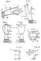
- the device comprises: a first element 1 figure 2-3-4-5 which consists of a gutter 9 with in the center a light dish 12 it aims to marry the cantle 5 figure 1 of a riding saddle, according to the model , the curve and the width of said cantle, the outer ends of the gutter are provided with grooves 13 in order to facilitate the opening of the crescent-shaped curve of the gutter 9; on the lower part is a slot 11 to allow passage to a strap 3 figure 1 to connect and fix all the elements on the saddle; transversely with respect to the gutter, under the lower part and on the internal side projects a projecting part 10 with a slight transverse rounding on the upper part, said projection comes to be applied under the cantle in the direction of the underside of the seat 7 figure 1 ; under the lower part of this projection is a slot 14 to allow passage to the strap.
- the second element 2 as shown in FIGS. 6-7-8-9-10 comprises: - an upper jaw 15 with its lower part slightly concave in the longitudinal direction and in the transverse direction as is clearly seen in FIG. 10, on its upper part is a slot 20 Figure 6-7-9-10 which aims to allow passage to the strap 3, - and a lower jaw 16; these two jaws, through the opening 28 which they define, are intended to marry the knob 6 in Figure 1 of the saddle; behind the closure of these jaws, there is a vertically oriented slot 19, intended to allow passage to the strap 3, this element is continued by a shoe 17 here provided flat on which is in this case laterally close to its end 21 at least two peripheral notches 18, the end of the shoe 21 of flat shape intended to rest on the ground, the grooves more or less separated with an inclination relative to the flat of the end 21, on the side of the face bottom of the shoe, are intended to be able, in the groove of the groove, to saw in a washer the end of the shoe in order to give another inclination to the element 2 when it is placed on
- a handle 3 front view Figure 11 and side view Figure 12 with a slot 22 to allow passage to the strap 3, connecting all the elements together.
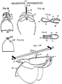
- This handle is L-shaped inverted, slightly closed and provided on the part lower of the upper horizontal branch 23 and near the internal angle with the branch arranged vertically 24 with a concavity 25 allowing stable support on a horizontal hanging support bar figure 16-17, in addition to its function of transport by hand, illustrated in figure 14.
- Figure 14 shows the elements secured to a saddle, in the transport position, with also a protective apron 26.
- This protective apron 26 aims to protect the fronts of the quarters 8 figure 1 of the saddle, in the center and at the top of the said apron there are two slots 27 to allow passage to the strap 3, in order to connect it under the lower part of element 2 figure 17-19.
- a saddle fitted with these elements can be placed on the ground vertically, the saddle being tilted, pressing on part 21 of shoe 17 of element 2 as shown in figure 15.
- the element 1 in figure 2 comprises a gutter, which aims to marry the cantle of a riding saddle, with a U-shaped section, this U can be more or less open as illustrated in Figure 5 section AA, it can also have a semicircular section.
- the protruding part 10 in FIG. 5 is slightly curved with the end rising, it can also be more or less straight, and more or less long.
- the external faces of the gutter can be flat, or curved.
- the jaws 15-16 of element 2 in figure 6-7 can be more or less deep and more or less wide.
- the lower part of the upper jaw 15 may be more or less concave in the longitudinal direction in figure 6 and in the transverse direction in figure 10.
- the upper part of the lower jaw 16 figure 6-10 can be more or less rounded in the transverse direction, but may also have a slight flat in the transverse medium over the entire length.
- the second element is no longer in the form of a muffle as illustrated in Figures 6 and 10, but in the form of a U-shaped profile defining a jaw by the branches (15) and (16) of the always concave U internally for the upper branch (15) and internally flat or convex for the lower branch (16), the said U being extended towards the rear by a part shoe (17) having in cross section an inverted T profile as shown or in U, the soul of the T or the branches of the U forming reinforcement or strut, thus making it possible to lighten and strengthen this element, the bottom part (21) of the U (17) or T (17) being curved on itself at the end to define the support zone at ground.
Landscapes
- Engineering & Computer Science (AREA)
- Mechanical Engineering (AREA)
- Purses, Travelling Bags, Baskets, Or Suitcases (AREA)
- Table Equipment (AREA)
- Walking Sticks, Umbrellas, And Fans (AREA)
Claims (11)
- Vorrichtung zur Erleichterung des Transports per Hand und der Lagerung eines Reitsattels, dadurch gekennzeichnet, daß die Vorrichtung dazu bestimmt ist, die Teile wie zum Beispiel den Sattelknauf und den Hinterzwiesel eines derartigen Reitsattels zu schützen, die bei der Handhabung und dem Transport im Transportwagen und beim Aufsetzen auf dem Boden dem Verschleiß und der Beschädigung stärker ausgesetzt sind, wobei besagte Vorrichtung aus einem ersten Element (1) in Klemmenform gebildet wird, das dazu bestimmt ist, sich auf dem Hinterzwiesel aufzustützen und einem zweiten Element (2) ebenfalls in enger und tiefer Klemmenform, das dazu bestimmt ist, durch seine zum Sattelknaufteil gerichtete Öffnung (28) rittlings auf besagten Sattelknauf gesetzt zu werden und daß sie darüber hinaus Verbindungsmittel zwischen den zwei Elementen (1) (2) umfaßt; die dazu bestimmt sind, diese zwei Elemente (1) (2) gegenüber auf dem Sattel festzuhalten, und daß die zwei Elemente (1) (2) aus einem halbsteifen Material realisiert sind, wie zum Beispiel: Plastik, Kautschuk, Harz.
- Vorrichtung gemäß Anspruch 1, dadurch gekennzeichnet, daß das erste Element in Klemmenform (1) sich durch einen Umschlagteil in Form einer gekrümmten Rinne (9) mit einem U-förmigen oder halbkreisförmigen Abschnitt, welcher horizontal in Richtung des Hinterzwiesel offen ist, auf dem Hinterzwiesel aufstützt und dessen Krümmung es ermöglicht, die Kontur besagten Hinterzwiesels anzunehmen, und daß der gekrümmte Teil den Aspekt einer Mondsichel aufweist, deren konkaver Teil auf seiner ganzen Länge ausgespart ist, um den Rinnenteil (9) zu definieren, der den Hinterzwiesel einhüllt, wobei der konvexe Teil sich auf dem Außenteil befindet, und daß sich ausgehend von der Mitte der Länge unter dem unteren Teil und auf der Innenseite sich senkrecht ein in Längsrichtung hervorstehender Teil (10) erstreckt, dessen Oberteil in Querrichtung leicht abgerundet ist, um in Richtung unter dem Sitz unter den Hinterzwiesel zu kommen.
- Vorrichtung gemäß Anspruch 1, dadurch gekennzeichnet, daß das zweite Element (2) in enger Klemmenform den Aspekt eines Us mit abgerundeten Zweigen oder einer Hand in einem Fausthandschuh aufweist, wobei "der Daumen" den unteren Teil (16) bildet und "die vier Finger zusammengefaßt" den oberen Teil (15), derart, daß er einen engeren unteren Teil definiert, und daß die Oberseite des unteren Teils (16) auf der ganzen Länge in Querrichtung leicht abgerundet ist, die Unterseite des oberen Teils (15) ist in Längsrichtung und in Querrichtung leicht konkav.
- Vorrichtung gemäß Anspruch 1, dadurch gekennzeichnet, daß die Verbindungsmittel zwischen den zwei Elementen (1) (2) durch einen Gurt gebildet werden.
- Vorrichtung gemäß Anspruch 1 und 4, dadurch gekennzeichnet, daß diese Elemente (1) (2) Aufnahme- und Verbindungsmittel mit dem Gurt umfassen, die auf dem ersten Element (1) aus einem Schlitz (11) gebildet werden, der sich in der Mitte der Länge der hinteren Abrundung der Mondsichelform befinden und gemäß einer querverlaufenden und vertikalen Ebene ausgerichtet ist, und eventuell aus einem zweiten Schlitz (14) oder Durchgang unter der Unterseite des gemäß einer horizontalen und längs verlaufenden Ebene ausgerichteten Vorsprungs (10) und auf dem zweiten Element (2) einen gemäß einer vertikalen und querverlaufenden Ebene ausgerichteten Schlitz (19), der sich hinter der Klemme befindet, und eventuell aus einem zweiten Schlitz (20) oder einem auf dem Oberteil der oberen Klemme angeordneten Durchgang, der gemäß einer horizontalen und längs verlaufenden Ebene ausgerichtet ist.
- Vorrichtung gemäß Anspruch 1 oder 3, dadurch gekennzeichnet, daß das zweite Element (2) sich an der gegenüberliegenden Seite der Öffnung (28) der Klemme durch einen Schuh (17) verlängert, dessen äußeres Ende querverlaufend flach ist und in Längsrichtung flach oder gekrümmt, senkrecht ausgerichtet und leicht geneigt ist im Verhältnis zur Anordnung der Achse der Klemme, die dazu bestimmt ist, nach einem Schwenken um 90° in einer vertikalen Position das Aufstützen des Sattels auf dem Boden zu gewährleisten.
- Vorrichtung gemäß Anspruch 2, dadurch gekennzeichnet, daß die Mondsichelform der Rinne (9) des ersten Elements (1) einen im zentralen Teil dickeren hinteren Teil aufweist, der sich zu den äußeren Enden hin verjüngt, sowie Rillen (13), die in Abständen in querverlaufenden Ebenen ausgehend vom Rand des Oberteils angeordnet sind, auf der Rückseite weiterlaufen und unter dem unteren Teil durchlaufen, um den anderen Rand zu erreichen, derart, daß die Flexibilität ermöglicht wird, um sich dem Profil des Hinterzwiesels anzupassen.
- Vorrichtung gemäß Anspruch 2, dadurch gekennzeichnet, daß der Boden der Rinne (9) des ersten Elements (1) im mittleren Teil eine leicht flache Seite (16) umfaßt.
- Vorrichtung gemäß Anspruch 2, dadurch gekennzeichnet, daß der Vorsprung (10) des ersten Elements (1) eine Oberseite aufweist, deren Ausrichtung in Längsrichtung zwischen einer horizontalen Richtung und einer leicht nach oben gekrümmten Richtung mit einem im Verhältnis zur den Teil in Mondsichelform enthaltenden Ebene leicht angehobenen äußeren Ende Inbegriffen ist.
- Vorrichtung gemäß einer der vorgenannten Ansprüche, dadurch gekennzeichnet, daß sie darüber hinaus ein Element umfaßt, das einen Transportgriff (4) bildet, der wenigstens mit einem Durchgang oder einem Verbindungsschlitz (22) mit dem Gurt (3) versehen ist und daß besagter Griff zwei Zweige (23) (24) in umgekehrter, leicht geschlossener L-Form oder in offener U-Form umfaßt und die im unteren Teil des horizontalen oberen Zweigs (23) und in der Nähe des Innenwinkels mit dem vertikal angeordneten Zweig mit einer Konkavität (25) ausgestattet ist, die ein stabiles Aufstützen auf einer horizontalen Befestigungsunterlage ermöglicht und daß sich der Schlitz (22) oder Durchgang horizontal zum unteren Teil des vertikalen Zweigs (24) befindet, der von der Innenseite des Ls zur Außenseite verläuft.
- Vorrichtung gemäß einem der vorgenannten Ansprüche, dadurch gekennzeichnet, daß er darüber hinaus ein eine Schürze bildendes Element (26) umfaßt, das ein peripheres Profil in Form eines Steigbügels in der Vorderansicht aufweist, der dazu bestimmt ist, die Vorderviertel des Sattels zu schützen, wenigstens mit einem Durchgang oder wenigstens einem Verbindungsschlitz (27) mit dem Gurt (3) versehen ist, sich in der Mitte und oberhalb besagter Schürze befindet.
Applications Claiming Priority (3)
| Application Number | Priority Date | Filing Date | Title |
|---|---|---|---|
| FR9605073 | 1996-04-23 | ||
| FR9605073A FR2747667B1 (fr) | 1996-04-23 | 1996-04-23 | Dispositif destine a proteger une selle d'equitation et a faciliter en outre son transport a la main et son stockage |
| PCT/FR1997/000714 WO1997039978A1 (fr) | 1996-04-23 | 1997-04-21 | Dispositif de protection et de transport d'une selle d'equitation |
Publications (2)
| Publication Number | Publication Date |
|---|---|
| EP0865409A1 EP0865409A1 (de) | 1998-09-23 |
| EP0865409B1 true EP0865409B1 (de) | 2001-11-28 |
Family
ID=9491480
Family Applications (1)
| Application Number | Title | Priority Date | Filing Date |
|---|---|---|---|
| EP97920796A Expired - Lifetime EP0865409B1 (de) | 1996-04-23 | 1997-04-21 | Schutz- und transportvorrichtung für reitsättel |
Country Status (5)
| Country | Link |
|---|---|
| EP (1) | EP0865409B1 (de) |
| AU (1) | AU2704297A (de) |
| DE (1) | DE69708592T2 (de) |
| FR (1) | FR2747667B1 (de) |
| WO (1) | WO1997039978A1 (de) |
Cited By (1)
| Publication number | Priority date | Publication date | Assignee | Title |
|---|---|---|---|---|
| KR101297202B1 (ko) * | 2011-10-27 | 2013-08-16 | 김종일 | 말 조종 핸들장치 |
Families Citing this family (1)
| Publication number | Priority date | Publication date | Assignee | Title |
|---|---|---|---|---|
| US11008212B2 (en) * | 2016-10-05 | 2021-05-18 | Adrian E. McPhaul | Saddles with eccentric or interchangeable saddle horn assemblies |
Family Cites Families (1)
| Publication number | Priority date | Publication date | Assignee | Title |
|---|---|---|---|---|
| EP0423969A1 (de) * | 1989-10-18 | 1991-04-24 | Vivi Pasban-Dowlatshahi | Sattelträgervorrichtung |
-
1996
- 1996-04-23 FR FR9605073A patent/FR2747667B1/fr not_active Expired - Fee Related
-
1997
- 1997-04-21 EP EP97920796A patent/EP0865409B1/de not_active Expired - Lifetime
- 1997-04-21 DE DE69708592T patent/DE69708592T2/de not_active Expired - Fee Related
- 1997-04-21 AU AU27042/97A patent/AU2704297A/en not_active Abandoned
- 1997-04-21 WO PCT/FR1997/000714 patent/WO1997039978A1/fr active IP Right Grant
Cited By (1)
| Publication number | Priority date | Publication date | Assignee | Title |
|---|---|---|---|---|
| KR101297202B1 (ko) * | 2011-10-27 | 2013-08-16 | 김종일 | 말 조종 핸들장치 |
Also Published As
| Publication number | Publication date |
|---|---|
| FR2747667A1 (fr) | 1997-10-24 |
| DE69708592T2 (de) | 2004-03-18 |
| EP0865409A1 (de) | 1998-09-23 |
| AU2704297A (en) | 1997-11-12 |
| WO1997039978A1 (fr) | 1997-10-30 |
| DE69708592D1 (de) | 2002-01-10 |
| FR2747667B1 (fr) | 1998-06-05 |
Similar Documents
| Publication | Publication Date | Title |
|---|---|---|
| EP0816202B1 (de) | Anordnung eines Werkzeugträgers auf einer Schubkarre | |
| EP0572291B1 (de) | Einheit von Fahrradsicherheitspedal und Radfahrschuh | |
| EP0492116B1 (de) | Skistiefel mit Hintereinstieg | |
| FR2688124A1 (fr) | Necessaire pour boite a casse-croute. | |
| FR2602451A1 (fr) | Rasoir de securite jetable | |
| FR2997375A1 (fr) | Cadre de bicyclette avec range-outils integre | |
| FR2666269A1 (fr) | Agrafe de cutter a lame retractable. | |
| FR2494647A1 (fr) | Support de charges a fixer sur le toit d'une voiture | |
| EP0865409B1 (de) | Schutz- und transportvorrichtung für reitsättel | |
| FR2761422A1 (fr) | Dispositif de fixation d'un element quelconque, tel qu'une poignee, sur une paroi | |
| EP1621237A1 (de) | Bindungssystem für einen Schuh auf einem Ski | |
| FR1465770A (fr) | Sacoche pour véhicules à deux roues, particulièrement pour cyclomoteurs ou petitsscooters | |
| FR2684056A1 (fr) | Dispositif porte-charge adaptable sur la rotule d'attelage d'un vehicule. | |
| FR2654642A1 (fr) | Sac pour clubs de golf a sangle bretelle de transport. | |
| FR2706408A1 (fr) | Véhicule du type poussette. | |
| EP0428436A1 (de) | Steigbügelriemenschnalle für Reitsattel | |
| FR2763909A1 (fr) | Dispositif pour le stockage et le transport de motocyclette | |
| WO2008110701A2 (fr) | Dispositif de maintien d'une cravate ou d'un article d'habillement similaire | |
| EP0056534A1 (de) | Stossstange für Handkarre bestimmt zur Aufnahme verschiedener Waren, insbesondere in Einkaufszentren | |
| EP2058578A2 (de) | Abnehmbarer Griff für Druckbehälter und entsprechender Behälter | |
| EP2003073B9 (de) | Modularer Bootshaken für Abdeckelement | |
| FR2496584A1 (fr) | Bidon avec support pour cycles | |
| EP0718181B1 (de) | Befestigungsvorrichtung für Tasche unter einem Fahrradsattel | |
| EP2823729A1 (de) | Behälterhalter zum Handgelenk | |
| FR2499513A1 (fr) | Conteneur pour le tri et le stockage temporaire ou permanent de documents et notamment pour la distribution du courrier, l'archivage de dossiers ou autre similaire |
Legal Events
| Date | Code | Title | Description |
|---|---|---|---|
| PUAI | Public reference made under article 153(3) epc to a published international application that has entered the european phase |
Free format text: ORIGINAL CODE: 0009012 |
|
| 17P | Request for examination filed |
Effective date: 19980109 |
|
| AK | Designated contracting states |
Kind code of ref document: A1 Designated state(s): BE DE FR GB |
|
| GRAG | Despatch of communication of intention to grant |
Free format text: ORIGINAL CODE: EPIDOS AGRA |
|
| 17Q | First examination report despatched |
Effective date: 20001218 |
|
| GRAG | Despatch of communication of intention to grant |
Free format text: ORIGINAL CODE: EPIDOS AGRA |
|
| GRAG | Despatch of communication of intention to grant |
Free format text: ORIGINAL CODE: EPIDOS AGRA |
|
| GRAH | Despatch of communication of intention to grant a patent |
Free format text: ORIGINAL CODE: EPIDOS IGRA |
|
| GRAH | Despatch of communication of intention to grant a patent |
Free format text: ORIGINAL CODE: EPIDOS IGRA |
|
| GRAA | (expected) grant |
Free format text: ORIGINAL CODE: 0009210 |
|
| AK | Designated contracting states |
Kind code of ref document: B1 Designated state(s): BE DE FR GB |
|
| REG | Reference to a national code |
Ref country code: GB Ref legal event code: IF02 |
|
| REF | Corresponds to: |
Ref document number: 69708592 Country of ref document: DE Date of ref document: 20020110 |
|
| GBT | Gb: translation of ep patent filed (gb section 77(6)(a)/1977) |
Effective date: 20020419 |
|
| PLBE | No opposition filed within time limit |
Free format text: ORIGINAL CODE: 0009261 |
|
| STAA | Information on the status of an ep patent application or granted ep patent |
Free format text: STATUS: NO OPPOSITION FILED WITHIN TIME LIMIT |
|
| 26N | No opposition filed | ||
| BERR | Be: reestablished |
Owner name: *SAUSSET ALEXANDRE Effective date: 20030211 |
|
| PGFP | Annual fee paid to national office [announced via postgrant information from national office to epo] |
Ref country code: DE Payment date: 20030328 Year of fee payment: 7 |
|
| REG | Reference to a national code |
Ref country code: FR Ref legal event code: CL |
|
| PG25 | Lapsed in a contracting state [announced via postgrant information from national office to epo] |
Ref country code: DE Free format text: LAPSE BECAUSE OF NON-PAYMENT OF DUE FEES Effective date: 20041103 |
|
| PGFP | Annual fee paid to national office [announced via postgrant information from national office to epo] |
Ref country code: FR Payment date: 20050419 Year of fee payment: 9 |
|
| PGFP | Annual fee paid to national office [announced via postgrant information from national office to epo] |
Ref country code: BE Payment date: 20050429 Year of fee payment: 9 |
|
| PGFP | Annual fee paid to national office [announced via postgrant information from national office to epo] |
Ref country code: GB Payment date: 20050521 Year of fee payment: 9 |
|
| PG25 | Lapsed in a contracting state [announced via postgrant information from national office to epo] |
Ref country code: GB Free format text: LAPSE BECAUSE OF NON-PAYMENT OF DUE FEES Effective date: 20060421 |
|
| PG25 | Lapsed in a contracting state [announced via postgrant information from national office to epo] |
Ref country code: BE Free format text: LAPSE BECAUSE OF NON-PAYMENT OF DUE FEES Effective date: 20060430 |
|
| GBPC | Gb: european patent ceased through non-payment of renewal fee |
Effective date: 20060421 |
|
| REG | Reference to a national code |
Ref country code: FR Ref legal event code: ST Effective date: 20061230 |
|
| BERE | Be: lapsed |
Owner name: *SAUSSET ALEXANDRE Effective date: 20060430 |
|
| PG25 | Lapsed in a contracting state [announced via postgrant information from national office to epo] |
Ref country code: FR Free format text: LAPSE BECAUSE OF NON-PAYMENT OF DUE FEES Effective date: 20060502 |