EP0865409B1 - Protecting and transporting device for a horse-riding saddle - Google Patents
Protecting and transporting device for a horse-riding saddle Download PDFInfo
- Publication number
- EP0865409B1 EP0865409B1 EP97920796A EP97920796A EP0865409B1 EP 0865409 B1 EP0865409 B1 EP 0865409B1 EP 97920796 A EP97920796 A EP 97920796A EP 97920796 A EP97920796 A EP 97920796A EP 0865409 B1 EP0865409 B1 EP 0865409B1
- Authority
- EP
- European Patent Office
- Prior art keywords
- jaw
- cantle
- saddle
- aperture
- slightly
- Prior art date
- Legal status (The legal status is an assumption and is not a legal conclusion. Google has not performed a legal analysis and makes no representation as to the accuracy of the status listed.)
- Expired - Lifetime
Links
Images


Classifications
-
- B—PERFORMING OPERATIONS; TRANSPORTING
- B68—SADDLERY; UPHOLSTERY
- B68C—SADDLES; STIRRUPS
- B68C1/00—Saddling equipment for riding- or pack-animals
- B68C1/002—Saddle-racks for supporting or cleaning purposes
Definitions
- the object of the present invention is to provide a system for protecting the parts exposed to wear and deterioration of a riding saddle, during handling, the ground, transport, more this system allows to carry the saddle easily, instead of carrying it on the arm which is inconvenient and tiring, and ability to carry at least two at a time, it allows the saddle to be placed on the ground vertically, without the help of a wall, or any other vertical support, it also allows to store the saddle on a horizontal bar, which avoids the costs of a saddle holder, or several saddles depending on the length of the bar: so on a 5 meter bar, we can store 11 stools, if they have this system, and in case they do not have one, it will require 11 saddles which is much more expensive.
- the document EP-A-0423969 describes a riding saddle support allowing the storage and the transport of such a saddle and represents the preamble of independent claim 1.
- the object of the invention is to provide a solution to such a problem, by providing a versatile device according to independent claim 1.
- the first element bears on the cantle by a part of an envelope in the form of curved gutter with section e nU or in a semicircle, open horizontally in the direction of the cantle and whose curvature allows it to follow the outline of said cantle,
- the curved part of the first element has the appearance of a crescent moon whose concave part is hollowed out over its entire length to define the gutter part intended to wrap the cantle, the convex part being situated on the external side and in that from the middle of the length, under the lower part and on the internal side projects perpendicularly a longitudinal projecting part, the upper part of which is slightly rounded in the transverse direction to come to bear under the cantle.
- the second element in the form of a narrow jaw has, according to a first mode of realization the appearance of a hand in a mitt, "the thumb” forming the part of lower jaw and the “four fingers” grouped together the upper jaw part so as to define a narrower lower jaw part and in that the face upper part of the lower jaw is slightly rounded in the direction transverse over the entire length, the underside of the upper jaw is slightly concave in the longitudinal direction and in the transverse direction, so that to marry respectively the lower and upper parts of the pommel.
- the connecting means between the two elements are constituted by a strap.
- the first and second jaw-shaped element in this case have means of reception and connection to the strap are made up: - on the first element, a slit or loop located in the middle of the length of the rear rounded shape crescent moon and oriented in a transverse and vertical plane, and completed by preferably by a second slot, or passing, under the underside of the projection, oriented along a horizontal and longitudinal plane, - and on the second element of a slot oriented in a vertical and transverse plane, located behind the jaw, preferably supplemented by a second slot, or pass, disposed on the part upper of the upper jaw, oriented in a horizontal and longitudinal plane.
- the second element extends away from the jaw opening and beyond from the slot by a shoe whose end is flat in the transverse direction and is flat or curved longitudinally, oriented perpendicularly and slightly inclined relative to the axis of the jaw, and intended to ensure the support on the ground of the saddle, in a vertical position, after a 90 ° pivoting of the latter.
- the crescent moon shape of the gutter of the first element has a part thicker rear in the central part which tapers at the ends, these last which can be provided with spaced grooves, arranged in planes transverse from the edge of the upper part continuing on the rear face and passing under the lower part to join the other edge, so as to increase the flexibility allowing it to conform to the profile of the cantle.
- the bottom of the gutter of the first element may include in the middle part a slight dish.
- the lower projection of the first element has an upper face whose orientation in the longitudinal direction is between a horizontal direction and a direction slightly curved upwards with one end slightly raised from the plan containing the crescent-shaped part.
- the assembly also includes an element forming carrying handle provided with at least one slit connecting to the strap and in that said handle has two branches, for example in the shape of an inverted L slightly closed or U open and provided, on the lower part of the branch horizontal upper and near the internal angle with the branch arranged vertically, with a concavity allowing stable support on a horizontal bar of hanging support, and in that the slot (s), or loops, are located horizontally at the bottom of the vertical branch going from the front to the rear side of this branch, possibly with an inclination facilitating blocking of the strap.
- an element forming carrying handle provided with at least one slit connecting to the strap and in that said handle has two branches, for example in the shape of an inverted L slightly closed or U open and provided, on the lower part of the branch horizontal upper and near the internal angle with the branch arranged vertically, with a concavity allowing stable support on a horizontal bar of hanging support, and in that the slot (s), or loops, are located horizontally at the bottom of the vertical branch going from the
- the assembly may further include an apron element having a profile stirrup-shaped device seen from the front, intended to protect the front parts from quarters of the saddle, provided with at least one pass, or at least one slit for connection to the strap located in the center and at the top of said apron, this apron being intended to be linked to the strap under the lower part of the second element.
- an apron element having a profile stirrup-shaped device seen from the front, intended to protect the front parts from quarters of the saddle, provided with at least one pass, or at least one slit for connection to the strap located in the center and at the top of said apron, this apron being intended to be linked to the strap under the lower part of the second element.
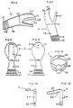
- the device comprises: a first element 1 figure 2-3-4-5 which consists of a gutter 9 with in the center a light dish 12 it aims to marry the cantle 5 figure 1 of a riding saddle, according to the model , the curve and the width of said cantle, the outer ends of the gutter are provided with grooves 13 in order to facilitate the opening of the crescent-shaped curve of the gutter 9; on the lower part is a slot 11 to allow passage to a strap 3 figure 1 to connect and fix all the elements on the saddle; transversely with respect to the gutter, under the lower part and on the internal side projects a projecting part 10 with a slight transverse rounding on the upper part, said projection comes to be applied under the cantle in the direction of the underside of the seat 7 figure 1 ; under the lower part of this projection is a slot 14 to allow passage to the strap.
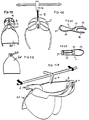
- the second element 2 as shown in FIGS. 6-7-8-9-10 comprises: - an upper jaw 15 with its lower part slightly concave in the longitudinal direction and in the transverse direction as is clearly seen in FIG. 10, on its upper part is a slot 20 Figure 6-7-9-10 which aims to allow passage to the strap 3, - and a lower jaw 16; these two jaws, through the opening 28 which they define, are intended to marry the knob 6 in Figure 1 of the saddle; behind the closure of these jaws, there is a vertically oriented slot 19, intended to allow passage to the strap 3, this element is continued by a shoe 17 here provided flat on which is in this case laterally close to its end 21 at least two peripheral notches 18, the end of the shoe 21 of flat shape intended to rest on the ground, the grooves more or less separated with an inclination relative to the flat of the end 21, on the side of the face bottom of the shoe, are intended to be able, in the groove of the groove, to saw in a washer the end of the shoe in order to give another inclination to the element 2 when it is placed on
- a handle 3 front view Figure 11 and side view Figure 12 with a slot 22 to allow passage to the strap 3, connecting all the elements together.
- This handle is L-shaped inverted, slightly closed and provided on the part lower of the upper horizontal branch 23 and near the internal angle with the branch arranged vertically 24 with a concavity 25 allowing stable support on a horizontal hanging support bar figure 16-17, in addition to its function of transport by hand, illustrated in figure 14.
- Figure 14 shows the elements secured to a saddle, in the transport position, with also a protective apron 26.
- This protective apron 26 aims to protect the fronts of the quarters 8 figure 1 of the saddle, in the center and at the top of the said apron there are two slots 27 to allow passage to the strap 3, in order to connect it under the lower part of element 2 figure 17-19.
- a saddle fitted with these elements can be placed on the ground vertically, the saddle being tilted, pressing on part 21 of shoe 17 of element 2 as shown in figure 15.
- the element 1 in figure 2 comprises a gutter, which aims to marry the cantle of a riding saddle, with a U-shaped section, this U can be more or less open as illustrated in Figure 5 section AA, it can also have a semicircular section.
- the protruding part 10 in FIG. 5 is slightly curved with the end rising, it can also be more or less straight, and more or less long.
- the external faces of the gutter can be flat, or curved.
- the jaws 15-16 of element 2 in figure 6-7 can be more or less deep and more or less wide.
- the lower part of the upper jaw 15 may be more or less concave in the longitudinal direction in figure 6 and in the transverse direction in figure 10.
- the upper part of the lower jaw 16 figure 6-10 can be more or less rounded in the transverse direction, but may also have a slight flat in the transverse medium over the entire length.
- the second element is no longer in the form of a muffle as illustrated in Figures 6 and 10, but in the form of a U-shaped profile defining a jaw by the branches (15) and (16) of the always concave U internally for the upper branch (15) and internally flat or convex for the lower branch (16), the said U being extended towards the rear by a part shoe (17) having in cross section an inverted T profile as shown or in U, the soul of the T or the branches of the U forming reinforcement or strut, thus making it possible to lighten and strengthen this element, the bottom part (21) of the U (17) or T (17) being curved on itself at the end to define the support zone at ground.
Description
La présente invention a pour but de procurer un système de protection des parties exposées à l'usure et à la détérioration d'une selle d'équitation, lors des manipulations, de la pose au sol, des transports, de plus ce système permet de porter la selle facilement, au lieu de la porter sur le bras ce qui est peu pratique et fatiguant, et de pouvoir en porter au moins deux à la fois, il permet de poser la selle au sol verticalement, sans l'aide d'un mur, ou tout autre appui vertical, il permet également de stocker la selle sur une barre horizontale, ce qui évite les frais d'un porte-selle, ou plusieurs selles suivant la longueur de la barre : ainsi sur une barre de 5 mètres, on peut stocker 11 selles, si elles sont munies de ce système, et dans le cas où elles n'en sont pas munies, il faudra 11 porte-selles ce qui est beaucoup plus coûteux.The object of the present invention is to provide a system for protecting the parts exposed to wear and deterioration of a riding saddle, during handling, the ground, transport, more this system allows to carry the saddle easily, instead of carrying it on the arm which is inconvenient and tiring, and ability to carry at least two at a time, it allows the saddle to be placed on the ground vertically, without the help of a wall, or any other vertical support, it also allows to store the saddle on a horizontal bar, which avoids the costs of a saddle holder, or several saddles depending on the length of the bar: so on a 5 meter bar, we can store 11 stools, if they have this system, and in case they do not have one, it will require 11 saddles which is much more expensive.
Il existe aussi des housses où l'on met la selle entièrement dedans et que l'on ferme au moyen de glissières, mais qui ne protège pas aussi efficacement les parties fragiles de ladite selle, de plus les housses ne permettent pas la pose au sol de la selle verticalement sans l'appui d'un mur, ou autre appui vertical, pas plus qu'elle ne permettent la facilité du stockage.There are also covers where you put the saddle entirely inside and close it slides, but does not protect fragile parts as effectively of said saddle, moreover the covers do not allow the laying on the ground of the saddle vertically without the support of a wall, or other vertical support, no more than it allow for ease of storage.
Le document EP-A-0423969 décrit un support selle d'équitation permettant le stockage et le
transport d'une telle selle et représente le préambule de la revendication indépendante 1.
L'invention a pour but d'apporter une solution à un tel problème, en fournissant un
dispositif polyvalent selon la revendication indépendante 1.
selon d'autres caractéristiques : le premier élément prend appui sur le troussequin par une
partie d'enveloppe en forme de gouttière incurvée à section e nU ou en demi-cercle,
ouverte horizontalement dans le sens du troussequin et dont la courbure
permet d'épouser le contour dudit troussequin, la partie incurvée du premier élément
présente l'aspect d'un croissant de lune dont la partie concave est évidée sur toute sa
longueur pour définir la partie gouttière destinée à envelopper le troussequin, la partie
convexe étant située côté externe et en ce que à partir du milieu de la longueur, sous
la partie inférieure et du côté interne se projette perpendiculairement une partie en
saillie longitudinale dont la partie supérieure est légèrement arrondie dans le sens
transversal pour venir en appui sous le troussequin.The document EP-A-0423969 describes a riding saddle support allowing the storage and the transport of such a saddle and represents the preamble of
The object of the invention is to provide a solution to such a problem, by providing a versatile device according to
Le deuxième élément en forme de mâchoire étroite présente selon un premier mode de réalisation l'aspect d'une main dans une mouffle, "le pouce" formant la partie de mâchoire inférieure et les "quatre doigts" regroupés la partie de mâchoire supérieure de sorte à définir une partie de mâchoire inférieure plus étroite et en ce que la face supérieure de la partie de la mâchoire inférieure est légèrement arrondie dans le sens transversal sur toute la longueur, la face inférieure de la mâchoire supérieure est légèrement concave dans le sens longitudinal et dans le sens transversal, de sorte à épouser les parties respectivement inférieure et supérieure du pommeau.The second element in the form of a narrow jaw has, according to a first mode of realization the appearance of a hand in a mitt, "the thumb" forming the part of lower jaw and the "four fingers" grouped together the upper jaw part so as to define a narrower lower jaw part and in that the face upper part of the lower jaw is slightly rounded in the direction transverse over the entire length, the underside of the upper jaw is slightly concave in the longitudinal direction and in the transverse direction, so that to marry respectively the lower and upper parts of the pommel.
Les moyens de liaison entre les deux éléments sont constitués par une sangle.The connecting means between the two elements are constituted by a strap.
Le premier et second élément en forme de mâchoire dans ce cas comportent des moyens de reception et de liaison à la sangle sont constitués:- sur le premier élément, d'une fente ou passant situé au milieu de la longueur de l'arrondi arrière de la forme en croissant de lune et orienté selon un plan transversal et vertical, et complété de préférence par une deuxième fente, ou passant, sous la face inférieure de la saillie, orienté selon un plan horizontal et longitudinal,- et sur le deuxième élément d'une fente orientée selon un plan vertical et transversal, située en arrière de la mâchoire, complétée préférentiellement par une deuxième fente, ou passant, disposé sur la partie supérieure de la mâchoire supérieure, orienté selon un plan horizontal et longitudinal.The first and second jaw-shaped element in this case have means of reception and connection to the strap are made up: - on the first element, a slit or loop located in the middle of the length of the rear rounded shape crescent moon and oriented in a transverse and vertical plane, and completed by preferably by a second slot, or passing, under the underside of the projection, oriented along a horizontal and longitudinal plane, - and on the second element of a slot oriented in a vertical and transverse plane, located behind the jaw, preferably supplemented by a second slot, or pass, disposed on the part upper of the upper jaw, oriented in a horizontal and longitudinal plane.
Le deuxième élément se prolonge à l'opposé de l'ouverture de la mâchoire et au delà de la fente par un sabot dont l'extrémité est plate dans le sens transversal et est plate ou incurvée dans le sens longitudinal, orientée perpendiculairement et légèrement inclinée par rapport à l'axe de la mâchoire, et destinée à assurer l'appui au sol de la selle, dans une position verticale, après un pivotement de 90° de cette dernière.The second element extends away from the jaw opening and beyond from the slot by a shoe whose end is flat in the transverse direction and is flat or curved longitudinally, oriented perpendicularly and slightly inclined relative to the axis of the jaw, and intended to ensure the support on the ground of the saddle, in a vertical position, after a 90 ° pivoting of the latter.
La forme en croissant de lune de la gouttière du premier élément présente une partie arrière plus épaisse en partie centrale qui va en s'affinant sur les extrémités, ces dernières pouvant être pourvues de rainures espacées , disposées dans des plans transversaux partant du bord de la partie supérieure continuant sur la face arrière et passant sous la partie inférieure pour rejoindre l'autre bord, de sorte à accroítre la flexibilité lui permettant de se conformer au profil du troussequin.The crescent moon shape of the gutter of the first element has a part thicker rear in the central part which tapers at the ends, these last which can be provided with spaced grooves, arranged in planes transverse from the edge of the upper part continuing on the rear face and passing under the lower part to join the other edge, so as to increase the flexibility allowing it to conform to the profile of the cantle.
Le fond de la gouttière du premier élément peut comporter en partie médiane un léger plat.The bottom of the gutter of the first element may include in the middle part a slight dish.
La saillie inférieure du premier élément présente une face supérieure dont l'orientation dans le sens longitudinal est comprise entre une direction horizontale et une direction légèrement incurvée vers le haut avec une extrémité légèrement relevée par rapport au plan contenant la partie en forme de croissant de lune.The lower projection of the first element has an upper face whose orientation in the longitudinal direction is between a horizontal direction and a direction slightly curved upwards with one end slightly raised from the plan containing the crescent-shaped part.
L'ensemble comporte selon une autre caractéristique en outre un élément formant poignée de transport muni d'au moins une fente de liaison à la sangle et en ce que ladite poignée comporte deux branches par exemple en forme de L renversé légèrement fermé ou de U ouvert et pourvu, sur la partie inférieure de la branche horizontale supérieure et près de l'angle interne avec la branche disposée verticalement, d'une concavité permettant un appui stable sur une barre horizontale de support d'accrochage, et en ce que la ou les fentes, ou passants, sont situés horizontalement à la partie inférieure de la branche verticale allant de la face avant à la face arrière de cette branche,avec éventuellement une inclinaison facilitant le blocage de la sangle.According to another characteristic, the assembly also includes an element forming carrying handle provided with at least one slit connecting to the strap and in that said handle has two branches, for example in the shape of an inverted L slightly closed or U open and provided, on the lower part of the branch horizontal upper and near the internal angle with the branch arranged vertically, with a concavity allowing stable support on a horizontal bar of hanging support, and in that the slot (s), or loops, are located horizontally at the bottom of the vertical branch going from the front to the rear side of this branch, possibly with an inclination facilitating blocking of the strap.
L'ensemble peut comporter en outre un élément formant tablier présentant un profil périphérique en forme d'étrier vu de face, destiné à protéger les parties avant des quartiers de la selle, muni d'au moins un passant, ou au moins une fente de liaison à la sangle situé au centre et en haut du dit tablier, ce tablier étant destiné à être lié à la sangle sous la partie inférieure du deuxième élément.The assembly may further include an apron element having a profile stirrup-shaped device seen from the front, intended to protect the front parts from quarters of the saddle, provided with at least one pass, or at least one slit for connection to the strap located in the center and at the top of said apron, this apron being intended to be linked to the strap under the lower part of the second element.
A titre d'illustration des schémas sont joints afin de bien comprendre l'invention, avec
l'aide de la description qui suit, référencée aux schémas, à titre non limitatif des
formes de réalisation préférées des éléments qui concernent le dispositif, ces schémas
représentent:
En référence à ces dessins le dispositif selon un mode de réalisation non limitatif
comprend:
un premier élément 1 figure 2-3-4-5 qui se compose d'une gouttière 9 avec au centre
un léger plat 12 elle a pour but d'épouser le troussequin 5 figure 1 d'une selle
d'équitation, selon le modèle, la courbe et la largeur dudit troussequin, les extrémités
externes de la gouttière sont pourvues de rainures 13 afin de faciliter l'ouverture de la
courbe en forme de croissant de lune de la gouttière 9; sur la partie inférieure se
trouve une fente 11 pour laisser le passage à une sangle 3 figure 1 pour relier et fixer
tous les élément sur la selle; transversalement par rapport à la gouttière, sous la partie
inférieure et du côté interne se projette une partie en saillie 10 avec un léger arrondi
transversal sur la partie supérieure, ladite saillie vient s'appliquer sous le troussequin
en direction du dessous du siège 7 figure 1; sous la partie inférieure de cette saillie se
trouve une fente 14 pour laisser le passage à la sangle.
Le deuxième élément 2 comme le montre les figures 6-7-8-9-10 comporte:- une
mâchoire supérieure 15 avec sa partie inférieure légèrement concave dans le sens
longitudinal et dans le sens transversal comme cela apparait clairement en figure 10,
sur sa partie supérieure se trouve une fente 20 figure 6-7-9-10 qui a pour but de
laisser le passage à la sangle 3,- et une mâchoire inférieure 16; ces deux mâchoires,
par l'ouverture 28 qu'elles définissent, ont pour but d'épouser le pommeau 6 figure 1
de la selle; en arrière de la fermeture de ces mâchoires, se trouve une fente 19 orientée
verticalement, ayant pour but de laisser le passage à la sangle 3, cet élément se
continue par un sabot 17 ici prévu plat sur lequel se trouve dans ce cas latéralement
proche de son extrémité 21 au moins deux entailles 18 périphériques, l'extrémité du
sabot 21 de forme plate destiné à prendre appui au sol, les rainures plus ou moins
écartées avec une inclinaison par rapport au plat de l'extrémité 21, du côté de la face
inférieure du sabot, ont pour but de pouvoir, dans la gorge de la rainure, scier en
rondelle l'extrémité du sabot afin de donner une autre inclinaison à l'élémént 2 lors de
sa pose au sol sur son plat, ceci permet de pouvoir l'adapter sur des modèles de selles
différents. Dans le cas d'une face d'extrémité présentant une courbure dans le sens
longitudinal, ces rainures sont superflues, l'appui s'effectuant quelque soit l'inclinaison
prise selon la ligne de tangence entre la surface courbe et le sol.With reference to these drawings, the device according to a nonlimiting embodiment comprises:
a
The
Afin d'améliorer le confort de transport manuel de l'ensemble par la sangle 3, il est
prévu en outre une poignée 3 vue de face figure 11 et de profil figure 12, avec une
fente 22 pour laisser le passage à la sangle 3, reliant tous les éléments ensemble. Cette
poignée est en forme de L renversé, légèrement fermé et pourvue sur la partie
inférieure de la branche horizontale supérieure 23 et près de l'angle interne avec la
branche disposée verticalement 24 d'une concavité 25 permettant un appui stable sur
une barre horizontale de support d'accrochage figure 16-17, en plus de sa fonction de
transport à la main, illustrée figure 14.In order to improve the comfort of manual transport of the assembly by
Une vue d'ensemble des éléments reliés entre eux sans la selle est illustrée figure 13.An overview of the elements connected together without the saddle is illustrated in Figure 13.
La figure 14 montre les éléments solidarisés à une selle, en position de transport, avec
également un tablier de protection 26.Ce tablier de protection 26 a pour but de
protéger les devants des quartiers 8 figure 1 de la selle, au centre et en haut dudit
tablier se trouvent deux fentes 27 pour laisser le passage à la sangle 3, afin de le relier
sous la partie inférieure de l'élément 2 figure 17-19.Figure 14 shows the elements secured to a saddle, in the transport position, with
also a protective apron 26.This
Une selle munie de ces éléments peut être posée au sol à la verticale, la selle étant
basculée, en appui sur la partie 21 du sabot 17 de l'élément 2 comme le montre la
figure 15.A saddle fitted with these elements can be placed on the ground vertically, the saddle being
tilted, pressing on
De manière non limitative l'élément 1 figure 2 comporte une gouttière, qui a pour but
d'épouser le troussequin d'une selle d'équitation, à section en forme de U, ce U peut
être plus ou moins ouvert comme l'illustre la figure 5 coupe AA, elle peut également
avoir une section en forme de demi-cercle.In a nonlimiting manner, the
La partie saillante 10 figure 5 est légèrement incurvée avec l'extrémité se relevant, elle
peut être aussi plus ou moins droite, et plus ou moins longue.The
Les faces externes de la gouttière peuvent être plates, ou bombées.The external faces of the gutter can be flat, or curved.
Les mâchoires 15-16 de l'élément 2 figure 6-7 peuvent être plus ou moins profondes
et plus ou moins larges.The jaws 15-16 of
La partie inférieure de la mâchoire supérieure 15 peut être plus ou moins concave
dans le sens longitudinal figure 6 et dans le sens transversal figure 10.The lower part of the
La partie supérieure de la mâchoire inférieure 16 figure 6-10 peut être plus ou moins
arrondie dans le sens transversal, mais peut également comporter un léger plat dans le
milieu transversal sur toute la longueur.The upper part of the
Selon les figures 20 et 21, le deuxième élement ne se présente plus sous forme d'une mouffle comme illustré aux figures 6 et 10, mais sous forme d'un profilé en U définissant une mâchoire par les branches (15) et (16) du U toujours concave intérieurement pour la branche supérieure (15) et plate ou convexe intérieurement pour la branche inférieure (16), le dit U étant prolongé vers l'arrière par une partie sabot (17) présentant en section transversal un profil en T renversé comme représenté ou en U, l'âme du T ou les branches du U formant renfort ou jambe de force, permettant ainsi d'alléger et de renforcer cet élément, la partie de fond (21) du U (17) ou T (17) étant recourbée sur elle même en extrémité pour définir la zone d'appui au sol.According to Figures 20 and 21, the second element is no longer in the form of a muffle as illustrated in Figures 6 and 10, but in the form of a U-shaped profile defining a jaw by the branches (15) and (16) of the always concave U internally for the upper branch (15) and internally flat or convex for the lower branch (16), the said U being extended towards the rear by a part shoe (17) having in cross section an inverted T profile as shown or in U, the soul of the T or the branches of the U forming reinforcement or strut, thus making it possible to lighten and strengthen this element, the bottom part (21) of the U (17) or T (17) being curved on itself at the end to define the support zone at ground.
Claims (11)
- Device for facilitating transporting by hand and storing a horse saddle, characterised in that the device is intended to protect the portions of this horse saddle, namely the pommel and the cantle which are the portions most exposed to wear and deterioration during handlings, horse box transports and placing on the ground, said device being constituted by a first jaw-shaped element (1) intended to take support on the cantle, and a second narrow deep element (2), also jaw-shaped, for mounting via its opening (28) orientated towards the pommel portion said pommel of the saddle, and in that it further comprises linking means between the two elements (1) (2) for keeping in support opposite these two elements (1) (2) on the saddle, and in that the two elements (1) (2) are made of a semi-rigid material such as plastic, rubber or resin.
- Device according to claim 1, characterised in that the first jaw-shaped element (1) takes support on the cantle via a gutter-shaped casing portion (9) bent with a U section or into a semi-circle open horizontally in the direction of the cantle and whose curve is able to marry the contour of said cantle, and in that the bent in portion has the aspect of a moon crescent whose concave portion is recessed over its entire length so as to define the gutter portion (9) casing the cantle, the convex portion being situated on the outer side, and in that from the middle of the length under the lower portion and from the internal side projects a longitudinal projecting portion (10) whose upper portion is slightly rounded in the transversal direction so as to come under the cantle in a direction below the seat.
- Device according to claim 1, characterised in that the second narrow jaw-shaped element 2) has the appearance of a U with rounded branches or of a hand in a mould, the "thumb" forming the lower portion (16) and the four fingers collectively the upper portion (15) so as to define a narrower lower portion, and in that in the upper face of the lower portion (16) is slightly rounded in the transversal direction over the entire length, the lower face of the upper portion (15) being slightly concave in the longitudinal and transversal directions.
- Device according to claim 1, characterised in that the linking means between the two elements (1) (2) are constituted by a strap.
- Device according to claims 1 and 4, characterised in that these elements (1) (2) comprise strap linking and receiving means constituted on the first element (1) of an aperture (11) situated at the middle of the length of the rear rounded portion of the moon crescent portion and orientated along a vertical transversal plane, and possibly a second aperture (14) or loop under the lower face of the projection (10) orientated along a longitudinal horizontal plane, and on the second element (2) an aperture (19) orientated along a transversal vertical plane situated behind the jaw and possibly a second aperture (20) or loop placed on the upper portion of the upper jaw orientated along a longitudinal horizontal plane.
- Device according to claim 1 or 3, characterised in that the second element (2) is extended opposite the opening (28) of the jaw by a shoe (17) whose extremity is transversally flat and is flat and bent inward in the longitudinal direction orientated perpendicularly and slightly slanted with respect to the arrangement of the axis of the jaw for supporting the saddle on the ground in a vertical position, after a tilting of 90°.
- Device according to claim 2, characterised in that the moon crescent shape of the gutter (9) of the first element (1) has a thicker rear portion at the central portion which becomes more refined on the extremities, as well as spaced grooves (13) placed in transversal planes starting from the edge of the upper portion continuing on the rear face and passing under the lower portion so as to join the other edge for providing flexibility so as to conform to the profile of the cantle.
- Device according to claim 2, characterised in that the bottom of the gutter (9) of the first element (1) comprises a light flat piece (16).
- Device according to claim 2, characterised in that the projection (10) of the first element (1) has one upper face whose orientation in a longitudinal direction is between a horizontal direction and a direction slightly bent upwards with one extremity slightly raised with respect to the plane containing the moon crescent-shaped portion.
- Device according to one of the preceding claims, characterised in that it further comprises an element (4) forming a transport handle fitted with at least one loop or an aperture (22) for linking to the strap (3), and in that said handle comprises two inverted L, slightly closed or open U-shaped branches (23) (24) and provided on the lower portion of the upper horizontal branch (23) and close to the internal angle with the branch placed vertically a concavity (25) allowing stable support on a horizontal hooking support bar, and in that the aperture (22) or loop is situated horizontally to the lower portion of the vertical branch (24) extending from the internal face of the L to the external face.
- Device according to one of the preceding claims, characterised in that it further comprises an element (26) forming an apron having a peripheral profile with a stirrup shape seen from the front and intended to protect the front portions of the segments of the saddle and fitted with at least one loop or aperture (27) for linking to the strap (3) situated at the centre and top of said apron.
Applications Claiming Priority (3)
| Application Number | Priority Date | Filing Date | Title |
|---|---|---|---|
| FR9605073 | 1996-04-23 | ||
| FR9605073A FR2747667B1 (en) | 1996-04-23 | 1996-04-23 | DEVICE FOR PROTECTING A RIDING SADDLE AND FURTHER FACILITATING HAND TRANSPORT AND STORAGE |
| PCT/FR1997/000714 WO1997039978A1 (en) | 1996-04-23 | 1997-04-21 | Protecting and transporting device for a horse-riding saddle |
Publications (2)
| Publication Number | Publication Date |
|---|---|
| EP0865409A1 EP0865409A1 (en) | 1998-09-23 |
| EP0865409B1 true EP0865409B1 (en) | 2001-11-28 |
Family
ID=9491480
Family Applications (1)
| Application Number | Title | Priority Date | Filing Date |
|---|---|---|---|
| EP97920796A Expired - Lifetime EP0865409B1 (en) | 1996-04-23 | 1997-04-21 | Protecting and transporting device for a horse-riding saddle |
Country Status (5)
| Country | Link |
|---|---|
| EP (1) | EP0865409B1 (en) |
| AU (1) | AU2704297A (en) |
| DE (1) | DE69708592T2 (en) |
| FR (1) | FR2747667B1 (en) |
| WO (1) | WO1997039978A1 (en) |
Cited By (1)
| Publication number | Priority date | Publication date | Assignee | Title |
|---|---|---|---|---|
| KR101297202B1 (en) * | 2011-10-27 | 2013-08-16 | 김종일 | The handle device for riding a hourse |
Families Citing this family (1)
| Publication number | Priority date | Publication date | Assignee | Title |
|---|---|---|---|---|
| US11008212B2 (en) * | 2016-10-05 | 2021-05-18 | Adrian E. McPhaul | Saddles with eccentric or interchangeable saddle horn assemblies |
Family Cites Families (1)
| Publication number | Priority date | Publication date | Assignee | Title |
|---|---|---|---|---|
| EP0423969A1 (en) * | 1989-10-18 | 1991-04-24 | Vivi Pasban-Dowlatshahi | Improvements in and relating to devices for supporting saddles |
-
1996
- 1996-04-23 FR FR9605073A patent/FR2747667B1/en not_active Expired - Fee Related
-
1997
- 1997-04-21 WO PCT/FR1997/000714 patent/WO1997039978A1/en active IP Right Grant
- 1997-04-21 EP EP97920796A patent/EP0865409B1/en not_active Expired - Lifetime
- 1997-04-21 AU AU27042/97A patent/AU2704297A/en not_active Abandoned
- 1997-04-21 DE DE69708592T patent/DE69708592T2/en not_active Expired - Fee Related
Cited By (1)
| Publication number | Priority date | Publication date | Assignee | Title |
|---|---|---|---|---|
| KR101297202B1 (en) * | 2011-10-27 | 2013-08-16 | 김종일 | The handle device for riding a hourse |
Also Published As
| Publication number | Publication date |
|---|---|
| DE69708592T2 (en) | 2004-03-18 |
| AU2704297A (en) | 1997-11-12 |
| FR2747667B1 (en) | 1998-06-05 |
| EP0865409A1 (en) | 1998-09-23 |
| WO1997039978A1 (en) | 1997-10-30 |
| DE69708592D1 (en) | 2002-01-10 |
| FR2747667A1 (en) | 1997-10-24 |
Similar Documents
| Publication | Publication Date | Title |
|---|---|---|
| EP0816202B1 (en) | Tool support mounted on a wheel barrow | |
| EP0572291B1 (en) | Cyclist safety pedal and shoe assembly | |
| EP0492116B1 (en) | Rear entry ski boot | |
| FR2688124A1 (en) | NECESSARY FOR SNACK BOX. | |
| FR2997375A1 (en) | BICYCLE FRAME WITH INTEGRATED RANGE TOOLS | |
| EP1195181A1 (en) | Improved binding of a boot to a snowboard | |
| FR2494647A1 (en) | LOAD SUPPORT TO FIX ONTO THE ROOF OF A CAR | |
| EP0966382B1 (en) | Removable cover for motorcycle fuel tank | |
| EP0865409B1 (en) | Protecting and transporting device for a horse-riding saddle | |
| EP1621237A1 (en) | Binding set for a shoe on a gliding board | |
| EP2030946A1 (en) | Horse riding safety stirrup | |
| FR1465770A (en) | Bag for two-wheeled vehicles, particularly for mopeds or small scooters | |
| FR2684056A1 (en) | Load holder device which can be fitted to the hitching ball of a vehicle | |
| FR2654642A1 (en) | Bag for golf clubs with shoulder transportation strap | |
| FR2706408A1 (en) | Stroller type vehicle. | |
| FR2654423A1 (en) | ETRIVIERE KNIFE FOR HORSE SADDLE. | |
| FR2763909A1 (en) | MOTORCYCLE STORAGE AND TRANSPORT DEVICE | |
| FR2506137A1 (en) | SUITCASE WITH COMPOSABLE MODULES WITH ADJUSTABLE HANDLE | |
| EP0056534A1 (en) | Bumper for a cart intended to receive different goods, especially in supermarkets | |
| EP2058578A2 (en) | Removable handle for a tank containing fluid under pressure and corresponding tank | |
| EP2003073B9 (en) | Modular gaff for covering element | |
| FR2496584A1 (en) | CAN WITH SUPPORT FOR CYCLES | |
| EP0718181B1 (en) | Fixation device for bag under a bicycle seat | |
| EP2823729A1 (en) | Container holder for wrist | |
| FR2499513A1 (en) | Filing container for documents - has rigid sides and flexible ends and base with fixtures to hold open or shut |
Legal Events
| Date | Code | Title | Description |
|---|---|---|---|
| PUAI | Public reference made under article 153(3) epc to a published international application that has entered the european phase |
Free format text: ORIGINAL CODE: 0009012 |
|
| 17P | Request for examination filed |
Effective date: 19980109 |
|
| AK | Designated contracting states |
Kind code of ref document: A1 Designated state(s): BE DE FR GB |
|
| GRAG | Despatch of communication of intention to grant |
Free format text: ORIGINAL CODE: EPIDOS AGRA |
|
| 17Q | First examination report despatched |
Effective date: 20001218 |
|
| GRAG | Despatch of communication of intention to grant |
Free format text: ORIGINAL CODE: EPIDOS AGRA |
|
| GRAG | Despatch of communication of intention to grant |
Free format text: ORIGINAL CODE: EPIDOS AGRA |
|
| GRAH | Despatch of communication of intention to grant a patent |
Free format text: ORIGINAL CODE: EPIDOS IGRA |
|
| GRAH | Despatch of communication of intention to grant a patent |
Free format text: ORIGINAL CODE: EPIDOS IGRA |
|
| GRAA | (expected) grant |
Free format text: ORIGINAL CODE: 0009210 |
|
| AK | Designated contracting states |
Kind code of ref document: B1 Designated state(s): BE DE FR GB |
|
| REG | Reference to a national code |
Ref country code: GB Ref legal event code: IF02 |
|
| REF | Corresponds to: |
Ref document number: 69708592 Country of ref document: DE Date of ref document: 20020110 |
|
| GBT | Gb: translation of ep patent filed (gb section 77(6)(a)/1977) |
Effective date: 20020419 |
|
| PLBE | No opposition filed within time limit |
Free format text: ORIGINAL CODE: 0009261 |
|
| STAA | Information on the status of an ep patent application or granted ep patent |
Free format text: STATUS: NO OPPOSITION FILED WITHIN TIME LIMIT |
|
| 26N | No opposition filed | ||
| BERR | Be: reestablished |
Owner name: *SAUSSET ALEXANDRE Effective date: 20030211 |
|
| PGFP | Annual fee paid to national office [announced via postgrant information from national office to epo] |
Ref country code: DE Payment date: 20030328 Year of fee payment: 7 |
|
| REG | Reference to a national code |
Ref country code: FR Ref legal event code: CL |
|
| PG25 | Lapsed in a contracting state [announced via postgrant information from national office to epo] |
Ref country code: DE Free format text: LAPSE BECAUSE OF NON-PAYMENT OF DUE FEES Effective date: 20041103 |
|
| PGFP | Annual fee paid to national office [announced via postgrant information from national office to epo] |
Ref country code: FR Payment date: 20050419 Year of fee payment: 9 |
|
| PGFP | Annual fee paid to national office [announced via postgrant information from national office to epo] |
Ref country code: BE Payment date: 20050429 Year of fee payment: 9 |
|
| PGFP | Annual fee paid to national office [announced via postgrant information from national office to epo] |
Ref country code: GB Payment date: 20050521 Year of fee payment: 9 |
|
| PG25 | Lapsed in a contracting state [announced via postgrant information from national office to epo] |
Ref country code: GB Free format text: LAPSE BECAUSE OF NON-PAYMENT OF DUE FEES Effective date: 20060421 |
|
| PG25 | Lapsed in a contracting state [announced via postgrant information from national office to epo] |
Ref country code: BE Free format text: LAPSE BECAUSE OF NON-PAYMENT OF DUE FEES Effective date: 20060430 |
|
| GBPC | Gb: european patent ceased through non-payment of renewal fee |
Effective date: 20060421 |
|
| REG | Reference to a national code |
Ref country code: FR Ref legal event code: ST Effective date: 20061230 |
|
| BERE | Be: lapsed |
Owner name: *SAUSSET ALEXANDRE Effective date: 20060430 |
|
| PG25 | Lapsed in a contracting state [announced via postgrant information from national office to epo] |
Ref country code: FR Free format text: LAPSE BECAUSE OF NON-PAYMENT OF DUE FEES Effective date: 20060502 |