EP1195181A1 - Improved binding of a boot to a snowboard - Google Patents
Improved binding of a boot to a snowboard Download PDFInfo
- Publication number
- EP1195181A1 EP1195181A1 EP01410113A EP01410113A EP1195181A1 EP 1195181 A1 EP1195181 A1 EP 1195181A1 EP 01410113 A EP01410113 A EP 01410113A EP 01410113 A EP01410113 A EP 01410113A EP 1195181 A1 EP1195181 A1 EP 1195181A1
- Authority
- EP
- European Patent Office
- Prior art keywords
- reinforcement
- retaining
- support piece
- rear support
- boot
- Prior art date
- Legal status (The legal status is an assumption and is not a legal conclusion. Google has not performed a legal analysis and makes no representation as to the accuracy of the status listed.)
- Granted
Links
Images


Classifications
-
- A—HUMAN NECESSITIES
- A63—SPORTS; GAMES; AMUSEMENTS
- A63C—SKATES; SKIS; ROLLER SKATES; DESIGN OR LAYOUT OF COURTS, RINKS OR THE LIKE
- A63C10/00—Snowboard bindings
- A63C10/24—Calf or heel supports, e.g. adjustable high back or heel loops
-
- A—HUMAN NECESSITIES
- A63—SPORTS; GAMES; AMUSEMENTS
- A63C—SKATES; SKIS; ROLLER SKATES; DESIGN OR LAYOUT OF COURTS, RINKS OR THE LIKE
- A63C10/00—Snowboard bindings
- A63C10/02—Snowboard bindings characterised by details of the shoe holders
- A63C10/04—Shoe holders for passing over the shoe
-
- A—HUMAN NECESSITIES
- A63—SPORTS; GAMES; AMUSEMENTS
- A63C—SKATES; SKIS; ROLLER SKATES; DESIGN OR LAYOUT OF COURTS, RINKS OR THE LIKE
- A63C10/00—Snowboard bindings
- A63C10/02—Snowboard bindings characterised by details of the shoe holders
- A63C10/10—Snowboard bindings characterised by details of the shoe holders using parts which are fixed on the shoe, e.g. means to facilitate step-in
Landscapes
- Footwear And Its Accessory, Manufacturing Method And Apparatuses (AREA)
- Mechanical Operated Clutches (AREA)
Abstract
Description
La présente invention concerne un dispositif de retenue d'une chaussure sur une planche de glisse sur neige destinée plus particulièrement à la pratique du surf, encore appelé snowboard.The present invention relates to a device for retaining a shoe on a snowboard intended for more particularly in the practice of surfing, also called snowboarding.
Pour la pratique du surf sur neige, l'utilisateur utilise des chaussures relativement souples retenues sur la planche grâce à des dispositifs de retenue comprenant une embase et une pièce d'appui arrière, ladite chaussure étant, par ailleurs, retenue en appui sur l'embase par des moyens de retenue réglables.For snowboarding, the user uses relatively flexible shoes retained on the board thanks to retainers comprising a base and a support piece rear, said shoe being, moreover, retained in abutment on the base by adjustable retaining means.
De façon connue en soi, la pièce d'appui arrière est articulée vers l'avant sur l'embase tandis qu'elle est bloquée en pivotement vers l'arrière par un système de butée pour assurer au surfeur un appui en flexion arrière suffisant, pour une conduite optimale du surf.In a manner known per se, the rear support piece is hinged towards the front on the base while it is locked in pivoting backwards by a stop system to provide the surfer with bending support sufficient rear, for optimal handling of the surf.
Actuellement, aucun élément d'appui arrière ne permet à l'utilisateur une conduite parfaite de son surf car aucun dispositif de retenue n'est adapté au style de pratique et au type de chaussure utilisé.Currently, no rear support element allows the user a perfect control of his surf because no device of restraint is not adapted to the style of practice and the type of shoe used.
La présente invention est un perfectionnement qui permet à l'utilisateur un appui arrière parfait quel que soit son style et le type de chaussure choisi.The present invention is an improvement which allows the user a perfect back support whatever his style and type of shoe chosen.
Ainsi, le dispositif de retenue d'une chaussure sur une planche de glisse sur neige destinée plus particulièrement à la pratique du surf, selon l'invention est du type comprenant une embase sur laquelle est montée une pièce d'appui arrière qui s'étend vers le haut, destinée à servir d'appui vers l'arrière pour la tige de la chaussure qui comprend sur sa partie centrale de paroi un renfort et est caractérisé en ce que le renfort est réglable en position verticale par rapport à la pièce d'appui arrière. Selon le mode d'exécution préféré, la pièce d'appui arrière est avantageusement montée pivotante par rapport à l'embase autour d'un axe transversal.Thus, the device for retaining a shoe on a board sliding on snow intended more particularly for the practice of surfing, according to the invention is of the type comprising a base on which is mounted a rear support piece which extends upwards, intended to serve as a support backwards for the upper of the shoe which includes on its part central wall a reinforcement and is characterized in that the reinforcement is adjustable in vertical position relative to the rear support piece. according to the preferred embodiment, the rear support piece is advantageously pivotally mounted relative to the base around a transverse axis.
Selon une caractéristique complémentaire, le renfort est une pièce indépendante de la pièce d'appui arrière et sa longueur est supérieure à sa largeur, tandis que ladite longueur est au moins supérieure à la moitié de la hauteur de la partie centrale de paroi de la pièce d'appui arrière, qui est mise en flexion vers l'arrière par la chaussure.According to an additional characteristic, the reinforcement is a part independent of the rear support piece and its length is greater than its width, while said length is at least more than half of the height of the central wall part of the rear support piece, which is flexion backwards by the shoe.
Selon une autre caractéristique, des moyens de réglage en position verticale du renfort sont prévus, qui sont constitués par au moins un système vis/écrou destiné à bloquer le renfort sur la pièce d'appui arrière et au moins un trou oblong ou lumière de réglage pour pouvoir déplacer le renfort longitudinal par rapport à la pièce d'appui arrière.According to another characteristic, means for adjusting the position vertical reinforcement are provided, which consist of at least one screw / nut system intended to lock the reinforcement on the rear support piece and at least one oblong hole or adjustment light to be able to move the longitudinal reinforcement relative to the rear support piece.
Selon un mode d'exécution préféré, la pièce d'appui arrière comprend dans le plan de symétrie général vertical deux lumières, disposées l'une au-dessus de l'autre, tandis que le renfort longitudinal comprend deux trous disposés eux aussi l'un au-dessus de l'autre, chacun des trous étant destiné à recevoir une vis de fixation tandis que chacune des lumières est destinée à recevoir un écrou qui comprend une embase coulissante de blocage en rotation.According to a preferred embodiment, the rear support piece includes in the general vertical plane of symmetry two lights, arranged one above the other, while the longitudinal reinforcement includes two holes also arranged one above the other, each holes being intended to receive a fixing screw while each lights is intended to receive a nut which includes a base sliding blocking in rotation.
Par ailleurs, des moyens de guidage sont prévus pour le déplacement vertical du renfort par rapport à la pièce d'appui arrière ainsi que des moyens d'indexation de la position du renfort, moyens constitués par un système comprenant une succession de dents de coopération. Furthermore, guide means are provided for the vertical displacement of the reinforcement relative to the rear support part as well means for indexing the position of the reinforcement, constituted means by a system comprising a succession of cooperation teeth.
Selon une autre caractéristique, la face d'extrémité inférieure du renfort constitue une butée destinée à venir en appui sur la bordure supérieure d'un arceau arrière solidaire de l'embase.According to another characteristic, the lower end face of the reinforcement constitutes a stop intended to come to bear on the edge upper of a rear hoop secured to the base.
Selon une caractéristique de l'invention, la pièce d'appui arrière (10) comprend sur sa partie centrale de paroi (19) un renfort (22) s'étendant du bas vers le haut, et inversement. On entendra par renfort toute pièce améliorant la rigidité et la tenue à la flexion vers l'arrière de la pièce d'appui arrière afin d'assurer à l'utilisateur un meilleur appui arrière lors de la pratique du surf, lui permettant d'avoir un meilleur contrôle de sa trajectoire.According to a characteristic of the invention, the rear support piece (10) comprises on its central wall part (19) a reinforcement (22) extending from bottom to top, and vice versa. We will hear by reinforcement any part improving the rigidity and the resistance to bending towards the rear of the rear support piece to provide the user with better rear support while surfing, allowing him to have better control of its trajectory.
On aura compris que le renfort est une pièce complémentaire améliorant la rigidité et la tenue à la flexion vers l'arrière de la pièce d'appui arrière qui permet d'assurer à l'utilisateur un meilleur appui arrière lors de la pratique du surf, et que son réglage en position lui permet de personnaliser cet appui assurant ainsi à l'utilisateur un meilleur contrôle de sa trajectoire.It will be understood that the reinforcement is a complementary part improving rigidity and resistance to bending towards the rear of the part back support which provides the user with better support back when surfing, and that its adjustment in position allows this support to be personalized, thus ensuring better user control of its trajectory.
D'autres caractéristiques et avantages de l'invention se dégageront de la description qui va suivre en regard des dessins annexés qui ne sont donnés qu'à titre d'exemples non limitatifs.Other characteristics and advantages of the invention will emerge of the description which will follow with regard to the appended drawings which are not given only by way of nonlimiting examples.
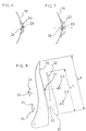
La figure 1 est une vue de dessus d'une planche de glisse telle qu'un surf muni de ses deux dispositifs de retenue des chaussures de l'utilisateur.Figure 1 is a top view of a gliding board such that a surfboard fitted with its two shoe retention devices the user.
La figure 2 est une vue latérale du dispositif de retenue selon l'invention avec la chaussure.Figure 2 is a side view of the retainer according to the invention with the shoe.
Les figures 3 à 14 sont des vues illustrant un premier mode de réalisation. Figures 3 to 14 are views illustrating a first mode of production.
La figure 3 est une vue en perspective arrière du dispositif de retenue, sans la chaussure.Figure 3 is a rear perspective view of the device restraint, without the shoe.
Les figures 4 et 5 sont des vues respectivement latérale et arrière de la pièce d'appui arrière, équipée de son renfort réglable.Figures 4 and 5 are side and rear views respectively of the rear support piece, equipped with its adjustable reinforcement.
La figure 6 est une vue en coupe selon AA des figures 4 et 5.FIG. 6 is a sectional view along AA of FIGS. 4 and 5.
La figure 7 est une vue en coupe selon BB des figures 4 et 5.FIG. 7 is a sectional view along BB of FIGS. 4 and 5.
La figure 8 est une vue latérale éclatée de la pièce d'appui arrière et de son renfort.Figure 8 is an exploded side view of the rear support piece and its reinforcement.
La figure 9 est une vue arrière de la pièce d'appui arrière seule.Figure 9 is a rear view of the rear support piece alone.
La figure 10 est une vue avant de la pièce d'appui arrière seule.Figure 10 is a front view of the rear support piece alone.
Les figures 11 à 14 sont des illustrations du renfort seul.Figures 11 to 14 are illustrations of the reinforcement alone.
La figure 11 est une vue arrière.Figure 11 is a rear view.
La figure 12 est une vue avant.Figure 12 is a front view.
La figure 13 est une vue en coupe selon CC de la figure 11.FIG. 13 is a sectional view along CC of FIG. 11.
La figure 14 est une vue en coupe selon DD de la figure 11.FIG. 14 is a sectional view along DD of FIG. 11.
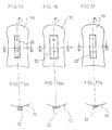
Les figures 15 à 20 illustrent des variantes d'exécution de la pièce d'appui arrière avec son renfort réglable.Figures 15 to 20 illustrate alternative embodiments of the part rear support with its adjustable reinforcement.
Les figures 15, 16, 17, 18, 19 et 20 sont des vues arrières, tandis que
les vues 15a, 16a, 17a, 18a, 19a et 20a sont des vues en coupe transversale
selon DD des figures correspondantes précédentes.Figures 15, 16, 17, 18, 19 and 20 are rear views, while
La figure 21 est une vue schématique arrière d'une autre variante d'exécution. Figure 21 is a schematic rear view of another variant execution.
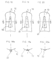
Les figures 22 et 23 sont des vues similaires aux figures 4 et 5, illustrant une variante d'exécution.Figures 22 and 23 are views similar to Figures 4 and 5, illustrating an alternative embodiment.
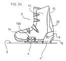
La figure 24 est une vue similaire à la figure 2, illustrant une variante d'exécution des moyens de retenue de la chaussure.Figure 24 is a view similar to Figure 2, illustrating a alternative embodiment of the shoe retaining means.
Une planche de glisse (1) destinée à la pratique du surf comprend deux dispositifs de retenue (2a, 2b) appelés aussi fixations pour retenir sur ledit surf les deux chaussures de l'utilisateur. Les deux dispositifs de retenue sont fixés sur la surface supérieure (3) du surf (1) de façon à ce que leur plan général de symétrie (P) soit en biais par rapport à l'axe (XX') dudit surf, tel que cela est illustré à la figure 1.A gliding board (1) intended for the practice of surfing comprises two retaining devices (2a, 2b) also called fixings for retaining on said surf the user's two shoes. The two devices retainers are fixed on the upper surface (3) of the surfboard (1) so that their general plane of symmetry (P) is at an angle to the axis (XX ') of said surf, as illustrated in FIG. 1.
On décrira ci-après l'un des dispositifs de retenue de la chaussure (2a, 2b) que l'on désignera sous la référence générale (2).One of the shoe retention devices will be described below. (2a, 2b) which will be designated under the general reference (2).
La figure 1 est une vue latérale montrant le dispositif de retenue (2) selon l'invention qui comprend une embase (4) ou plaque support s'étendant horizontalement d'une extrémité avant (5) à une extrémité arrière (6), tandis qu'une pièce d'appui arrière (10) est disposée sur cette embase.Figure 1 is a side view showing the retainer (2) according to the invention which comprises a base (4) or support plate extending horizontally from a front end (5) to one end rear (6), while a rear support piece (10) is disposed on this base.
Ladite embase (4) est limitée latéralement de chaque côté par un rebord latéral (7a, 7b), un rebord latéral gauche (7a) et un rebord latéral droit (7b), chacun des rebords étant constitué par une paroi sensiblement verticale destinée à retenir latéralement la chaussure et ses moyens de retenue (16, 17).Said base (4) is limited laterally on each side by a lateral rim (7a, 7b), a left lateral rim (7a) and a lateral rim straight (7b), each of the flanges being constituted by a wall substantially vertical intended to laterally retain the shoe and its means of restraint (16, 17).
Les deux rebords latéraux (7a, 7b) sont reliés à l'arrière par un arceau arrière (8). Ajoutons qu'à l'arrière il est prévu une pièce d'appui arrière (10) s'étendant vers le haut (HA) et disposée pivotante sur les bords latéraux (7a, 7b) autour d'un axe transversal (9). The two side edges (7a, 7b) are connected at the rear by a rear hoop (8). Add that at the back there is a support piece rear (10) extending upward (HA) and pivotally arranged at the edges lateral (7a, 7b) around a transverse axis (9).
La chaussure (11) de l'utilisateur présente une tige (12) relativement souple par rapport à sa partie basse (13) qui s'étend d'une extrémité avant (14) à une extrémité arrière (15) ou talon qui est en appui vers l'arrière (AR) contre l'arceau arrière (8).The user's shoe (11) has an upper (12) relatively flexible compared to its lower part (13) which extends front end (14) to a rear end (15) or heel which is in abutment backwards (AR) against the rear arch (8).
De façon connue en soi, la chaussure (11) est selon le mode
d'exécution illustré, retenue sur l'embase (4) par un organe de retenue
avant (16) retenant l'avant de la chaussure, et un organe de retenue arrière
(17) retenant ladite chaussure au niveau du coup de pied. L'organe de
retenue avant (16) et l'organe de retenue arrière (17) comprennent
avantageusement des moyens de réglage pour les adapter aux dimensions
volumiques de ladite chaussure. Bien entendu, tous autres moyens de
retenue pour la chaussure peuvent être prévus, autres que des sangles
souples réglables comme, par exemple, sans sangle, et notamment du type
à chaussage et déchaussage automatique, appelé communément
«step in», tel que cela est illustré schématiquement à la figure 24, et
comme, par exemple, ceux décrits dans le brevet français publié sous le
numéro 2 742 997.In a manner known per se, the shoe (11) is according to the mode
illustrated, retained on the base (4) by a retaining member
front (16) retaining the front of the shoe, and a rear retaining member
(17) retaining said shoe at the kick. The organ of
front retainer (16) and the rear retainer (17) include
advantageously adjustment means to adapt them to the dimensions
volumes of said shoe. Of course, all other means of
shoe retainers may be provided, other than straps
flexible adjustable like, for example, without strap, and in particular of the type
with automatic putting on and taking off, commonly called
"Step in", as shown schematically in Figure 24, and
such as, for example, those described in the French patent published under the
Notons que la pièce d'appui arrière (10) est destinée à servir d'appui vers l'arrière pour la tige (12) de la chaussure. A cet effet, la pièce d'appui arrière (10) est une paroi qui s'étend vers le haut (HA) pour envelopper l'arrière (18) de ladite tige (12). Ainsi, la pièce d'appui arrière (10) est une paroi courbe formée par une partie centrale de paroi (19) prolongée latéralement par deux parties latérales de paroi (20a, 20b), une partie latérale gauche (20a) et une partie latérale droite (20b). Ajoutons que ladite pièce d'appui arrière (10) est articulée par rapport à l'embase par les extrémités inférieures (200a, 200b) de chacune des parois latérales (20a, 20b) de la pièce d'appui arrière (10) qui comprennent chacune à cet effet un trou (100) destiné à recevoir, par exemple, un rivet (21) de liaison et d'articulation. La pièce d'appui arrière (10) articulée sur l'embase peut donc pivoter vers l'avant selon R1, pour pouvoir, en l'absence de la chaussure, être, par exemple, complètement repliée pour le transport.Note that the rear support piece (10) is intended to serve back support for the upper (12) of the shoe. For this purpose, the room rear support (10) is an upwardly extending wall (HA) for wrapping the rear (18) of said rod (12). So the back support piece (10) is a curved wall formed by a central wall part (19) laterally extended by two lateral wall parts (20a, 20b), one left side part (20a) and a right side part (20b). Let’s add that said rear support piece (10) is articulated relative to the base by the lower ends (200a, 200b) of each of the side walls (20a, 20b) of the rear support piece (10) which each include in this effect a hole (100) intended to receive, for example, a rivet (21) of connection and articulation. The rear support piece (10) articulated on the base can therefore pivot forwards along R1, to be able, in the absence of the shoe, for example, be completely folded up for transport.
Bien entendu, on ne sortirait pas de l'invention si la pièce d'appui arrière n'était pas pivotante sur l'embase, mais seulement pivotante par rapport à l'embase, voir montée mobile par rapport à l'embase par tout système autre qu'une articulation comme, par exemple, un montage déformable élastiquement.Of course, we would not go outside the invention if the support piece rear was not swivel on the base, but only swivel by relative to the base, see mobile mounting relative to the base by any system other than a joint such as, for example, an assembly elastically deformable.
Selon une caractéristique de l'invention, la pièce d'appui arrière (10) comprend sur sa partie centrale de paroi (19) un renfort (22) s'étendant du bas vers le haut, et inversement. On entendra par renfort toute pièce améliorant la rigidité et la tenue à la flexion vers l'arrière de la pièce d'appui arrière afin d'assurer à l'utilisateur un meilleur appui arrière lors de la pratique du surf lui permettant d'avoir un meilleur contrôle de sa trajectoire.According to a characteristic of the invention, the rear support piece (10) comprises on its central wall part (19) a reinforcement (22) extending from bottom to top, and vice versa. We will hear by reinforcement any part improving the rigidity and the resistance to bending towards the rear of the rear support piece to provide the user with better rear support when practicing surfing allowing him to have better control of its trajectory.
Le renfort (22) est, selon l'invention, réglable en position verticale par rapport à la pièce d'appui arrière. A cet effet, ledit renfort est une pièce complémentaire indépendante de la pièce d'appui arrière (10) et y est fixé grâce à des moyens de blocage et de réglage en position verticale.The reinforcement (22) is, according to the invention, adjustable in vertical position relative to the rear support piece. To this end, said reinforcement is a part independent of and attached to the rear support piece (10) by means of blocking and adjustment in vertical position.
Ces moyens permettent à l'utilisateur de régler la position relative verticale du renfort (22) dans une position déterminée par rapport à la pièce d'appui arrière (10) et de le fixer et le bloquer dans la position choisie.These means allow the user to adjust the relative position vertical of the reinforcement (22) in a determined position relative to the rear support piece (10) and fix and lock it in position chosen.
Les moyens de fixation et de réglage sont constitués par au moins un système vis/écrou (23, 24) destiné à bloquer le renfort (22) sur la pièce d'appui arrière (10) et au moins un trou oblong ou lumière de réglage (25a, 25b) pour pouvoir déplacer le renfort longitudinal par rapport à la pièce d'appui arrière. Ajoutons que l'on ne sortirait pas du cadre de l'invention si les moyens de fixations étaient d'un tout autre genre comme, par exemple, des moyens ne nécessitant pas d'outillage particulier, et notamment, un système à came ou autre.The fixing and adjusting means consist of at least a screw / nut system (23, 24) intended to block the reinforcement (22) on the part rear support (10) and at least one oblong hole or adjustment light (25a, 25b) to be able to move the longitudinal reinforcement relative to the rear support piece. We would add that we would not go beyond the framework of the invention if the fixing means were of a completely different kind such as, for example, means not requiring special tools, and in particular, a cam system or the like.
Ainsi, la pièce d'appui arrière (10) comprend dans le plan de symétrie général vertical (P) deux lumières (25a, 25b) disposées l'une au-dessus de l'autre, tandis que le renfort longitudinal (22) comprend deux trous (26a, 26b) disposés eux aussi l'un au-dessus de l'autre. Chacun des trous (26a, 26b) est destiné à recevoir une vis de fixation (23) tandis que chacune des lumières (25a, 25b) est destinée à recevoir un écrou (24) qui comprend une embase coulissante (26) de blocage en rotation.Thus, the rear support piece (10) comprises in the plane of general vertical symmetry (P) two lights (25a, 25b) arranged one above the other, while the longitudinal reinforcement (22) comprises two holes (26a, 26b) also arranged one above the other. Each holes (26a, 26b) is intended to receive a fixing screw (23) while that each of the lights (25a, 25b) is intended to receive a nut (24) which comprises a sliding base (26) for blocking rotation.
Le renfort est une pièce profilée en matière plastique dont la longueur (L1) est supérieure à sa largeur (L2), tandis que ladite longueur (L1) est au moins supérieure à la moitié de la hauteur (L3) de la partie centrale de paroi (19) de la pièce d'appui arrière (10) qui est mise en flexion vers l'arrière par la tige de la chaussure.The reinforcement is a profiled plastic part, the length (L1) is greater than its width (L2), while said length (L1) is at least more than half the height (L3) of the part wall center (19) of the rear support piece (10) which is bending backwards through the upper of the shoe.
Le dispositif de l'invention comprend, par ailleurs, des moyens de guidage pour le déplacement vertical du renfort (22) par rapport à la pièce d'appui arrière (11). A cet effet, la pièce d'appui arrière (10) comprend vers l'arrière (AR) sur sa partie centrale (19) une saillie verticale de guidage (27) de section rectangulaire, tandis que la face avant (28) du renfort (22) comprend un profil en creux correspondant (29) qui s'étend verticalement, destiné à recevoir ladite saillie de guidage. Ainsi le renfort peut être déplacé verticalement par coulissement vertical sur la saillie de guidage.The device of the invention also comprises means for guide for the vertical movement of the reinforcement (22) relative to the part rear support (11). To this end, the rear support piece (10) comprises towards the rear (AR) on its central part (19) a vertical guide projection (27) of rectangular section, while the front face (28) of the reinforcement (22) comprises a corresponding hollow profile (29) which extends vertically, intended to receive said guide projection. So the reinforcement can be moved vertically by vertical sliding on the guide projection.
Par ailleurs, des moyens d'indexation de la position du renfort sont prévus, constitués par un système comprenant une succession de dents de coopération. Ainsi sur la partie basse de la saillie de guidage de la pièce d'appui arrière (10) sont prévues une succession de dents horizontales (30) destinées à coopérer avec une succession de dents correspondantes (31) disposées au fond du profil en creux (29) du renfort (22).Furthermore, means for indexing the position of the reinforcement are provided, consisting of a system comprising a succession of cooperation teeth. Thus on the lower part of the guide projection of the rear support piece (10) are provided with a succession of teeth horizontal (30) intended to cooperate with a succession of teeth corresponding (31) arranged at the bottom of the hollow profile (29) of the reinforcement (22).
Par ailleurs, la section transversale extérieure du renfort (22) peut prendre différentes formes et peut être constante ou variable dans ses formes et/ou dans ses dimensions.Furthermore, the external cross section of the reinforcement (22) can take different forms and can be constant or variable in its shapes and / or in its dimensions.
Selon le mode d'exécution préféré et illustré plus particulièrement aux figures 4, 5, 11, 12, 13 et 14, la section transversale du renfort (22) est variable pour avoir une section dont la largeur (L2) et l'épaisseur (L4) diminuent progressivement vers le haut.According to the preferred embodiment and illustrated more particularly in Figures 4, 5, 11, 12, 13 and 14, the cross section of the reinforcement (22) is variable to have a section whose width (L2) and thickness (L4) gradually decrease upwards.
Par ailleurs, la section renfort (22) est avantageusement un profilé sensiblement trapézoïdal.Furthermore, the reinforcement section (22) is advantageously a profile substantially trapezoidal.
On notera que, selon la variante préférée, le renfort (22) est courbe et la courbure générale a son centre de courbure du côté interne (INT).It will be noted that, according to the preferred variant, the reinforcement (22) is curved and the general curvature has its center of curvature on the internal side (INT).
Bien entendu, le renfort (22) peut avoir une section rectangulaire ou carrée, voire en portion de cylindre, de dimensions constantes ou variables, comme cela est illustré respectivement aux figures 15, 16, 17, 18, 19 et 20.Of course, the reinforcement (22) may have a rectangular section or square, or even in cylinder portion, of constant dimensions or variables, as illustrated in Figures 15, 16, 17, 18 respectively, 19 and 20.
Selon la variante représentée par les figures 15 et 15a, la section du renfort est carrée.According to the variant shown in Figures 15 and 15a, the section of the reinforcement is square.
Selon la variante représentée par les figures 16 et 16a, la section du renfort est rectangulaire.According to the variant represented by FIGS. 16 and 16a, the section of the reinforcement is rectangular.
Selon la variante représentée par les figures 17 et 17a, la section du renfort est une portion angulaire de cylindre. According to the variant shown in Figures 17 and 17a, the section of the reinforcement is an angular portion of cylinder.
Selon la variante représentée par les figures 18 et 18a, la section du renfort est carrée et ses dimensions diminuent progressivement vers le haut.According to the variant shown in Figures 18 and 18a, the section of the reinforcement is square and its dimensions gradually decrease towards the high.
Selon la variante représentée par les figures 19 et 19a, la section du renfort est rectangulaire et ses dimensions diminuent progressivement vers le haut.According to the variant shown in Figures 19 and 19a, the section of the reinforcement is rectangular and its dimensions gradually decrease to the top.
Selon la variante représentée par les figures 20 et 20a, la section du renfort est une portion de cylindre et ses dimensions diminuent progressivement vers le haut.According to the variant shown in Figures 20 and 20a, the section of the reinforcement is a portion of cylinder and its dimensions decrease gradually upwards.
Par ailleurs, le plan général de symétrie (P1) du renfort peut être dans le plan général de symétrie (P) de la pièce d'appui arrière (10), tel que cela est illustré aux figures 15 à 20, mais il peut en être autrement, comme pour la variante représentée à la figure 21.Furthermore, the general plane of symmetry (P1) of the reinforcement can be in the general plane of symmetry (P) of the rear support piece (10), such that this is illustrated in Figures 15-20, but it may be otherwise, as for the variant shown in Figure 21.
Selon cette variante, le plan (P1) de symétrie général du renfort est concourant avec le plan général de symétrie (P) de la pièce d'appui arrière pour être divergeant vers le haut et vers le côté interne (INT) de la chaussure.According to this variant, the plane (P1) of general symmetry of the reinforcement is concurrent with the general plane of symmetry (P) of the rear support piece to be diverging upwards and towards the internal side (INT) of the shoe.
On a compris que, grâce au coulissement possible du renfort sur la pièce d'appui arrière et aux moyens de réglage d'indexation et de blocage, il est possible de déplacer le renfort (22) par rapport à la pièce d'appui arrière (10) soit vers le haut (F1), soit vers le bas (F2), pour permettre à l'utilisateur d'adapter la raideur de ses appuis arrières à ses besoins.We have understood that, thanks to the possible sliding of the reinforcement on the rear support piece and to the indexing and locking adjustment means, it is possible to move the reinforcement (22) relative to the support piece rear (10) either up (F1) or down (F2), to allow the user to adapt the stiffness of his rear supports to his needs.
Par ailleurs, la face d'extrémité inférieure (32) du renfort (22) constitue une butée destinée à venir en appui sur la bordure supérieure (33) de l'arceau arrière (8). Ce système de butée empêche le pivotement vers l'arrière selon (R2) de la pièce d'appui arrière (10) ce qui permet à l'utilisateur d'avoir en flexion arrière une très bonne retenue vers l'arrière de la tige (12) de sa chaussure. Etant donné que la position du renfort est réglable, l'utilisateur pourra ainsi modifier la position angulaire de son appui arrière.Furthermore, the lower end face (32) of the reinforcement (22) constitutes a stop intended to come to bear on the upper edge (33) of the rear hoop (8). This stop system prevents pivoting rearward along (R2) of the rear support piece (10) which allows the user to have a very good rearward bending in rear bending the upper (12) of his shoe. Since the position of the reinforcement is adjustable, the user will be able to modify the angular position of his rear support.
Le renfort (22) peut être réalisé dans un matériau identique ou différent de celui de l'appui arrière. Ainsi, il peut être en matériau plastique tel qu'en polyamide ou en matériau composite ou métallique.The reinforcement (22) can be made of an identical material or different from that of the rear support. So it can be made of material plastic such as polyamide or composite or metallic material.
Les figures 22 et 23 représentent une autre variante selon laquelle le renfort est un barreau en matériau composite dont la position verticale est réglable, pour être fixé à l'appui arrière par son extrémité inférieure, tandis que le reste de sa longueur est disposée coulissante.Figures 22 and 23 show another variant according to which the reinforcement is a bar of composite material whose vertical position is adjustable, to be fixed to the rear support by its lower end, while the rest of its length is sliding.
La figure 24 illustre une variante de moyens de retenue pour la
chaussure, du type dont la retenue de la chaussure sur l'embase (4) n'est
pas réalisée par des sangles (16,17) comme précédemment décrit, mais par
un dispositif central (160) comme, par exemple, celui décrit dans le brevet
antérieur numéro 2 742 997. Ainsi la pièce de retenue arrière (10) est
montée sur sa propre embase (4') différente de l'embase (4) de retenue de
la chaussure.FIG. 24 illustrates a variant of retaining means for the
shoe, of the type whose retention of the shoe on the base (4) is not
not carried by straps (16,17) as previously described, but by
a central device (160) such as, for example, that described in the patent
Bien entendu, l'invention n'est pas limitée aux modes de réalisation décrits et représentés à titre d'exemples, mais elle comprend aussi tous les équivalents techniques ainsi que leurs combinaisons.Of course, the invention is not limited to the modes of realization described and represented as examples, but it includes also all technical equivalents and their combinations.
Claims (16)
Applications Claiming Priority (2)
| Application Number | Priority Date | Filing Date | Title |
|---|---|---|---|
| FR0012703A FR2814962B1 (en) | 2000-10-05 | 2000-10-05 | IMPROVEMENT FOR A DEVICE FOR RETAINING A FOOTWEAR ON A SURF SNOW SLIDING BOARD |
| FR0012703 | 2000-10-05 |
Publications (2)
| Publication Number | Publication Date |
|---|---|
| EP1195181A1 true EP1195181A1 (en) | 2002-04-10 |
| EP1195181B1 EP1195181B1 (en) | 2005-07-27 |
Family
ID=8855013
Family Applications (1)
| Application Number | Title | Priority Date | Filing Date |
|---|---|---|---|
| EP01410113A Expired - Lifetime EP1195181B1 (en) | 2000-10-05 | 2001-09-10 | Improved binding of a boot to a snowboard |
Country Status (5)
| Country | Link |
|---|---|
| US (1) | US6729642B2 (en) |
| EP (1) | EP1195181B1 (en) |
| AT (1) | ATE300337T1 (en) |
| DE (1) | DE60112208T2 (en) |
| FR (1) | FR2814962B1 (en) |
Cited By (1)
| Publication number | Priority date | Publication date | Assignee | Title |
|---|---|---|---|---|
| EP1228789A1 (en) * | 2001-01-31 | 2002-08-07 | Salomon S.A. | Support device integrated with an assembly for binding a shoe to a sports article, or to a shoe |
Families Citing this family (19)
| Publication number | Priority date | Publication date | Assignee | Title |
|---|---|---|---|---|
| FR2824275B1 (en) | 2001-05-04 | 2003-08-15 | Rossignol Sa | IMPROVEMENT FOR A DEVICE FOR RETAINING A SHOE ON A SNOWBOARD OF THE SURF TYPE |
| FR2834475B3 (en) * | 2002-01-09 | 2004-03-05 | Salomon Sa | DEVICE FOR RETAINING A SHOE ON A SPORTS MACHINE |
| AT412616B (en) * | 2002-02-01 | 2005-05-25 | Atomic Austria Gmbh | BINDING DEVICE FOR SPORTS EQUIPMENT, ESPECIALLY FOR A SNOWBOARD |
| US7219924B2 (en) * | 2002-04-30 | 2007-05-22 | Pride Mobility Products Corporation | Rear wheel drive power wheelchair with ground-contacting anti-tip wheels |
| FR2853841B1 (en) * | 2003-04-15 | 2005-07-08 | Salomon Sa | DEVICE FOR RETAINING A SHOE ON A SPORT MACHINE |
| US6969075B2 (en) * | 2003-10-21 | 2005-11-29 | The Burton Corporation | Snowboard binding with reduced vertical profile |
| US7614638B2 (en) * | 2004-08-02 | 2009-11-10 | The Burton Corporation | Convertible toe strap |
| US7686321B2 (en) * | 2006-12-01 | 2010-03-30 | The Burton Corporation | Highback with textile-like material for support |
| US8469372B2 (en) | 2008-10-23 | 2013-06-25 | Bryce M. Kloster | Splitboard binding apparatus |
| US9238168B2 (en) * | 2012-02-10 | 2016-01-19 | Bryce M. Kloster | Splitboard joining device |
| US9266010B2 (en) | 2012-06-12 | 2016-02-23 | Tyler G. Kloster | Splitboard binding with adjustable leverage devices |
| US9254434B2 (en) | 2014-06-23 | 2016-02-09 | Tzy Shenq Enterprise Co., Ltd. | Fixation seat for ski shoe |
| US9114309B1 (en) * | 2014-06-23 | 2015-08-25 | Tzy Shenq Enterprise Co., Ltd. | Fixation seat for ski shoe |
| US9604122B2 (en) | 2015-04-27 | 2017-03-28 | Bryce M. Kloster | Splitboard joining device |
| US10029165B2 (en) | 2015-04-27 | 2018-07-24 | Bryce M. Kloster | Splitboard joining device |
| JP6997632B2 (en) * | 2018-01-12 | 2022-01-17 | 株式会社カーメイト | Snowboard binding highback |
| US11117042B2 (en) | 2019-05-03 | 2021-09-14 | Bryce M. Kloster | Splitboard binding |
| US11938394B2 (en) | 2021-02-22 | 2024-03-26 | Bryce M. Kloster | Splitboard joining device |
| US20230415023A1 (en) * | 2022-06-28 | 2023-12-28 | Trd U.S.A., Inc. | Sit skis and sit ski assemblies |
Citations (3)
| Publication number | Priority date | Publication date | Assignee | Title |
|---|---|---|---|---|
| DE4416023C1 (en) * | 1994-05-06 | 1995-10-12 | Christian Breuer | Binding for snowboard or ski boots |
| US5727797A (en) * | 1996-02-06 | 1998-03-17 | Preston Binding Company | Snowboard binding assembly with adjustable forward lean backplate |
| DE19802304A1 (en) * | 1998-01-22 | 1999-07-29 | Marker Deutschland Gmbh | Snowboard boot and binding combination with calf support |
Family Cites Families (16)
| Publication number | Priority date | Publication date | Assignee | Title |
|---|---|---|---|---|
| IT8021894V0 (en) * | 1980-05-23 | 1980-05-23 | Nordica Spa | DEVICE FOR THE ADJUSTMENT OF THE INCLINATION OF THE KNEE PARTICULARLY IN SKI BOOTS. |
| US4979760A (en) * | 1989-12-26 | 1990-12-25 | Derrah Steven J | Soft boot binding for snow boards |
| IT228031Y1 (en) * | 1992-05-15 | 1998-02-05 | Calzaturificio Tecnica Spa | IMPROVED SIDE TILT REGULATOR |
| FR2742997B1 (en) | 1996-01-03 | 1998-03-13 | Rossignol Sa | IMPROVEMENT FOR A DEVICE FOR RETAINING A SHOE TO A SNOW BOARD |
| DE29700632U1 (en) * | 1997-01-17 | 1997-06-05 | Marker Deutschland Gmbh | Snowboard binding |
| US5894684A (en) * | 1996-01-26 | 1999-04-20 | Vans, Inc. | Snowboard boot ankle support device |
| US6027136A (en) * | 1997-01-08 | 2000-02-22 | The Burton Corporation | System for preventing toe-edge travel of a hi-back |
| FR2774304B1 (en) * | 1998-01-30 | 2000-04-28 | Salomon Sa | DEVICE FOR RETAINING A SHOE ON A SNOWBOARD |
| US6231057B1 (en) * | 1998-10-09 | 2001-05-15 | The Burton Corporation | Highback with an adjustable shape |
| US6406040B1 (en) * | 1998-10-21 | 2002-06-18 | Nike, Inc. | Highback snowboard binding |
| US6283482B1 (en) * | 1998-12-07 | 2001-09-04 | The Burton Corporation | Binding with a tool-free selectively adjustable leg support member |
| US6360454B1 (en) * | 1998-12-07 | 2002-03-26 | The Burton Corporation | Tongue stiffener for footwear |
| FR2793156B1 (en) * | 1999-05-07 | 2001-11-23 | Salomon Sa | DEVICE FOR RETAINING A SHOE ON A SNOWBOARD |
| US6364323B1 (en) * | 1999-12-07 | 2002-04-02 | The Burton Corporation | Tool-free adjustment system for a leg support member of a binding |
| US6543793B1 (en) * | 2000-10-03 | 2003-04-08 | The Burton Corporation | Highback formed of multiple materials |
| US6390492B1 (en) * | 2000-02-22 | 2002-05-21 | Sidway Sports, Llc | Snowboard binding system with tool-less adjustments |
-
2000
- 2000-10-05 FR FR0012703A patent/FR2814962B1/en not_active Expired - Fee Related
-
2001
- 2001-09-10 EP EP01410113A patent/EP1195181B1/en not_active Expired - Lifetime
- 2001-09-10 AT AT01410113T patent/ATE300337T1/en not_active IP Right Cessation
- 2001-09-10 DE DE60112208T patent/DE60112208T2/en not_active Expired - Lifetime
- 2001-10-05 US US09/972,455 patent/US6729642B2/en not_active Expired - Fee Related
Patent Citations (3)
| Publication number | Priority date | Publication date | Assignee | Title |
|---|---|---|---|---|
| DE4416023C1 (en) * | 1994-05-06 | 1995-10-12 | Christian Breuer | Binding for snowboard or ski boots |
| US5727797A (en) * | 1996-02-06 | 1998-03-17 | Preston Binding Company | Snowboard binding assembly with adjustable forward lean backplate |
| DE19802304A1 (en) * | 1998-01-22 | 1999-07-29 | Marker Deutschland Gmbh | Snowboard boot and binding combination with calf support |
Cited By (1)
| Publication number | Priority date | Publication date | Assignee | Title |
|---|---|---|---|---|
| EP1228789A1 (en) * | 2001-01-31 | 2002-08-07 | Salomon S.A. | Support device integrated with an assembly for binding a shoe to a sports article, or to a shoe |
Also Published As
| Publication number | Publication date |
|---|---|
| US20020070530A1 (en) | 2002-06-13 |
| US6729642B2 (en) | 2004-05-04 |
| ATE300337T1 (en) | 2005-08-15 |
| FR2814962A1 (en) | 2002-04-12 |
| DE60112208D1 (en) | 2005-09-01 |
| FR2814962B1 (en) | 2002-12-27 |
| EP1195181B1 (en) | 2005-07-27 |
| DE60112208T2 (en) | 2006-05-24 |
Similar Documents
| Publication | Publication Date | Title |
|---|---|---|
| EP1195181B1 (en) | Improved binding of a boot to a snowboard | |
| EP0650385B1 (en) | Device for holding a boot on a snowboard | |
| EP1103290B1 (en) | Snowboard binding | |
| FR2912373A1 (en) | Automatic locking and unlocking bicycle pedal for e.g. road race, has elastic return unit whose flexure element with one end that is housed in pedal body, where another end of flexure element is supported against maintaining unit | |
| EP0465794A1 (en) | Ski with a fileted upper surface | |
| EP1254684B1 (en) | Improved binding of a boot to a snowboard | |
| EP0838248B1 (en) | Holding device for a boot on a snowboard | |
| EP1329246B1 (en) | Improved binding of a boot to a snowboard | |
| EP1125604B1 (en) | Snowboard binding | |
| EP1108452B1 (en) | Interface device for engaging a boot to a snowboard | |
| FR2820335A1 (en) | INTERFACE PLATE TO BE SOLIDARIZED ON THE UPPER FACE OF A SKI | |
| CH690899A5 (en) | Device for fixing a boot to a snowboard. | |
| EP1234604B1 (en) | Interface for a snowboard | |
| EP1555050A2 (en) | Improvement on a strap retainer or similar for fixing shoe to a sport article | |
| CH673400A5 (en) | ||
| EP0940160A1 (en) | Snow sport device | |
| EP2213342B1 (en) | Strapping system for retaining a boot on a sports equipment | |
| EP1433504A1 (en) | Device for fixing a shoe on a sporting good | |
| FR2880547A1 (en) | Top wedging and rotation blocking device for snowshoe`s fixing plate, has sliding unit moved in translation by front and rear connecting rods in order to occupy engaged and disengaged positions | |
| FR2823681A1 (en) | Ski binding with quick fit and release mechanism has intermediate raised plate with side rails for lateral clamps | |
| EP0470384B1 (en) | Ski boot | |
| FR2761611A1 (en) | Holder element for retaining shoe on e.g ski, snowboard | |
| FR2973748A1 (en) | Seat for e.g. car such as two-door car, has elastic restoring connection including two ends, and anchoring unit movable relative to fixed rail so as to vary position of one of ends of elastic restoring connection relative to fixed rail | |
| EP1673147B1 (en) | Cross-country ski system provided with a direct bearing lateral surface | |
| FR2796852A1 (en) | Connector piece for ski shoe bindings, comprises front and rear base plates joined via expandable connecting part |
Legal Events
| Date | Code | Title | Description |
|---|---|---|---|
| PUAI | Public reference made under article 153(3) epc to a published international application that has entered the european phase |
Free format text: ORIGINAL CODE: 0009012 |
|
| AK | Designated contracting states |
Kind code of ref document: A1 Designated state(s): AT BE CH CY DE DK ES FI FR GB GR IE IT LI LU MC NL PT SE TR Kind code of ref document: A1 Designated state(s): AT DE FR IT |
|
| AX | Request for extension of the european patent |
Free format text: AL;LT;LV;MK;RO;SI |
|
| 17P | Request for examination filed |
Effective date: 20020503 |
|
| AKX | Designation fees paid |
Free format text: AT DE FR IT |
|
| GRAP | Despatch of communication of intention to grant a patent |
Free format text: ORIGINAL CODE: EPIDOSNIGR1 |
|
| GRAS | Grant fee paid |
Free format text: ORIGINAL CODE: EPIDOSNIGR3 |
|
| GRAA | (expected) grant |
Free format text: ORIGINAL CODE: 0009210 |
|
| AK | Designated contracting states |
Kind code of ref document: B1 Designated state(s): AT DE FR IT |
|
| REF | Corresponds to: |
Ref document number: 60112208 Country of ref document: DE Date of ref document: 20050901 Kind code of ref document: P |
|
| PLBE | No opposition filed within time limit |
Free format text: ORIGINAL CODE: 0009261 |
|
| STAA | Information on the status of an ep patent application or granted ep patent |
Free format text: STATUS: NO OPPOSITION FILED WITHIN TIME LIMIT |
|
| 26N | No opposition filed |
Effective date: 20060428 |
|
| PGFP | Annual fee paid to national office [announced via postgrant information from national office to epo] |
Ref country code: AT Payment date: 20070924 Year of fee payment: 7 |
|
| PGFP | Annual fee paid to national office [announced via postgrant information from national office to epo] |
Ref country code: IT Payment date: 20080929 Year of fee payment: 8 |
|
| PG25 | Lapsed in a contracting state [announced via postgrant information from national office to epo] |
Ref country code: AT Free format text: LAPSE BECAUSE OF NON-PAYMENT OF DUE FEES Effective date: 20080910 |
|
| PGFP | Annual fee paid to national office [announced via postgrant information from national office to epo] |
Ref country code: DE Payment date: 20090824 Year of fee payment: 9 |
|
| PG25 | Lapsed in a contracting state [announced via postgrant information from national office to epo] |
Ref country code: IT Free format text: LAPSE BECAUSE OF NON-PAYMENT OF DUE FEES Effective date: 20090910 |
|
| REG | Reference to a national code |
Ref country code: DE Ref legal event code: R119 Ref document number: 60112208 Country of ref document: DE Effective date: 20110401 |
|
| PG25 | Lapsed in a contracting state [announced via postgrant information from national office to epo] |
Ref country code: DE Free format text: LAPSE BECAUSE OF NON-PAYMENT OF DUE FEES Effective date: 20110401 |
|
| REG | Reference to a national code |
Ref country code: FR Ref legal event code: PLFP Year of fee payment: 15 |
|
| PGFP | Annual fee paid to national office [announced via postgrant information from national office to epo] |
Ref country code: FR Payment date: 20150929 Year of fee payment: 15 |
|
| REG | Reference to a national code |
Ref country code: FR Ref legal event code: ST Effective date: 20170531 |
|
| PG25 | Lapsed in a contracting state [announced via postgrant information from national office to epo] |
Ref country code: FR Free format text: LAPSE BECAUSE OF NON-PAYMENT OF DUE FEES Effective date: 20160930 |