EP0865226A2 - System zur Verbesserung des Raumklangeffektes von Stereoton oder kodierten Tonsignalen - Google Patents
System zur Verbesserung des Raumklangeffektes von Stereoton oder kodierten Tonsignalen Download PDFInfo
- Publication number
- EP0865226A2 EP0865226A2 EP97117057A EP97117057A EP0865226A2 EP 0865226 A2 EP0865226 A2 EP 0865226A2 EP 97117057 A EP97117057 A EP 97117057A EP 97117057 A EP97117057 A EP 97117057A EP 0865226 A2 EP0865226 A2 EP 0865226A2
- Authority
- EP
- European Patent Office
- Prior art keywords
- sound
- signal
- stereo
- frequency range
- spatial effect
- Prior art date
- Legal status (The legal status is an assumption and is not a legal conclusion. Google has not performed a legal analysis and makes no representation as to the accuracy of the status listed.)
- Granted
Links
Images


Classifications
-
- H—ELECTRICITY
- H04—ELECTRIC COMMUNICATION TECHNIQUE
- H04S—STEREOPHONIC SYSTEMS
- H04S1/00—Two-channel systems
- H04S1/002—Non-adaptive circuits, e.g. manually adjustable or static, for enhancing the sound image or the spatial distribution
Definitions
- the present invention relates to a system for improving a spatial effect of stereo sound or encoded sound, and particularly relates to a system for improving a spatial effect of stereo sound or encoded sound, e.g. sound processed by Dolby Prologic, AC3, THX or Digital Surround, which is suitably applied to a three dimensional stereo sound image processing technique.
- a spatial effect in stereo sound or encoded sound and background sound of music are emphasized when a three dimensional image sound is reproduced from a stereo signal using only two speakers; getting a "live" sound effect.
- the L-R signal for forming a stereo sound image should be subjected to filters, gain controlling circuits and other calculating circuits in order to obtain a sound which has a three dimensional effect.
- the amount of the differential component of the left and right channel signals becomes extremely small in an output signal because the system is constructed such that the frequency of the L-R signal is processed and then the thus processed signal is calculated in the left and right channels, respectively.
- the signal component is lacking in the middle frequency range, i.e. in a voice frequency range, and in the low frequency range, since most of the component of such processed signal are distributed in the high frequency range.
- the present invention has for its purpose to provide a system for improving a spatial effect of stereo sound or encoded sound, by which the loss of the original sound can be restricted to a minimum and the sense of three dimensional sound image in the reproduced sound may be improved.
- the background sound which is inevitably decreased during the first signal mixing step of a sound recording process, is enhanced when the sound is reproduced, so that a "live" sense of sound can be obtained.
- the circuitry consists such that neither the L+R signals nor the L-R signals are processed in various circuits as is done in the above-mentioned prior arts; the channel signals are processed, but importance is given to each channel signal independently.
- the unbalance of an acoustic field can be restricted to a minimum and the ratio between signal and noise and the total harmonic distortion can be decreased, so that the loss of the original sound signal becomes smaller and the directivity and spatial effect of sound can be improved and the "live" sense of sound is increased.
- the output signal has a construction such that a gain characteristic is increased in a low frequency range taking an original sound signal as a leading part, the original signal and a differential component between the left and right side channels signals exist with a ratio of fifty/fifty in the middle frequency range, and a gain characteristic is increased in the higher frequency range taking the differential signal component of the left and right channel signals as a leading part, so that a natural and real sound effect can be produced. It should also be noted that it is possible to improve the sound reproducing characteristic of the audio signal even if cheap or middle priced audio equipment is used.
- the system according to the invention which has a symmetrical circuit construction so as to suitably process stereo signals, has realized a new concept of a "surround" system where the spatial effect of sound is improved using a differential component between the left and right channel sound signals, while keeping the circuit construction simple so that it can be said that the ratio between signal and noise is not deteriorated.
- the basic construction of the system according to the present invention is to comprise a spatial effect enhancing portion where a spatial image of sound is extracted in a frequency selective manner, a frequency band enhancing portion where the original sound is enhanced in low frequency range and in the middle frequency range, and a channel matrix portion for calculating signals in a matrix manner.
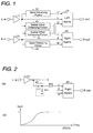
- Fig. 1 is a block diagram showing a basic construction of a first embodiment of the system for improving a spatial effect of stereo sound or encoded sound according to the invention.
- the system is applied to audio equipment as a signal processor where a three dimensional stereo sound image signal is produced from stereo signals.
- the system of the first embodiment comprises a spatial effect enhancing portion (30)(40), a band enhancing portion (50)(60) and a channel matrix portion (70)(80) in each of left and right signal lines.
- the spatial effect enhancing portion (30)(40) the left and right input signals (L-in)(R-in) are inputted, respectively, to produce a signal for enhancing a spatial effect and a directivity of sound in a reproduced sound;
- the band enhancing portions (50)(60) the left and right input signals (L-in)(R-in) are inputted, respectively, to generate a signal for enhancing the signal components of the middle and low frequency ranges of an original sound;
- the channel matrix portions (70)(80) an output signal of said spatial effect improving portion, an output signal of said band enhancing portion, and the left and right channel signals are calculated in a matrix manner.
- the system according to the present invention is constructed such that the left and right input signals (L-in)(R-in) are supplied to the portions via buffer amplifiers (10) (20), respectively.
- the reason why the buffer amplifiers are provided is to make a high signal input impedance. By the high signal input impedance, the attenuation and deterioration of signals, caused when the signals are transmitted through the circuits, is reduced in the view of frequencies.
- the input signals (L-in)(R-in) are inputted into the left and right side spatial effect enhancing portions (30)(40) and into the left and right side band enhancing portions (50)(60) via the buffer amplifiers (10)(20), respectively.
- Output signals from the spatial effect enhancing portions (30)(40) and the band enhancing portions (50)(60) are further supplied into the left and right side channel matrix portions (70)(80), respectively.
- each input signal (L-in)(R-in) is supplied into the channel matrix portion (70)(80), directly.
- signals L' and R' are produced which are used for generating directivity and spatial effect in a reproduced sound.
- the output signal L' of the left side spatial effect enhancing portion (40) is supplied to the right side matrix portion (80) and the output signal R' of the right side spatial effect enhancing portion (30) is supplied to the left matrix portion (70); calculations of L-R' and R-L' are conducted in the matrix portions (70) and (80), respectively.
- the signals L'' and R'' are inputted into the left and right side matrix portions (70) (80) and are added to the results of said calculation of L-R' and R-L'.
- the output signals L' and R' of the spatial effect enhancing portions (30)(40) and the output signals L'' and R'' of the band enhancing portions (50)(60) are calculated together in a matrix manner, so that the calculation of L-R'+L'' is conducted in the left side channel to generate an output signal of (L-OUT) and the calculation of R-L'+R'' is conducted in the right side channel to output an output signal of (R-OUT).
- the spatial effect enhancing portions (30)(40) have a characteristic as a high pass filter, while the band enhancing portions (50)(60) have a characteristic as a low pass filter.
- the output signal of the left side channel (L-OUT) becomes L+(L''-R')
- the output signal of the right side channel (R-OUT) becomes R+(R''-L') .
- the original signal can be kept as it is in the middle frequency range without respect to the fact that the signal components of the left and right side original signals are the same or not in the middle frequency range.
- the signal components R' and L' only have a small gain. Therefore, when the calculations of L-R'+L'' and R-L'+R'' are done in the matrix portions, the amount of signal components of L+L'' and R+R'' become relatively great. As a result, the signal component of the original signal in the lower frequency range is enhanced when signals are outputted from the matrix portions.
- the frequency range of the original sound signal is roughly divided into three ranges, i.e. a low frequency range, a middle frequency range and a high frequency range; the original channel signals are enhanced in the lower frequency range; the original channel signals are kept as they are in the middle frequency range; and the mutually subtracted signal component of the original left and right channel signals are enhanced in the higher frequency range.
- the spatial effect and the directivity of sound of the reproduced sound is improved, while keeping the balance of sound well extending all over the frequency ranges.
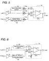
- Fig. 2 is a block diagram depicting a detail construction of the system for improving a spatial effect of stereo sound or encoded sound according to the present invention:
- Fig. 2(a) is a circuit diagram of the spatial effect enhancing portion and
- Fig. 2(b) is a graph showing the frequency-gain characteristic of an output of the spatial effect enhancing portion.
- the spatial effect enhancing portion is provided in each channel and has a circuit construction to produce the signal R' or L' which is used for enhancing the spatial effect, the directivity and the background of the reproduced sound.
- the basic concept of the spatial effect enhancing portion is to pass the signal components existing in a higher frequency range, which is determined by taking the voice frequency range as a center part, to produce the signals R' and L'; the signals R' or L' are subtracted from the relevant channel signal in the matrix portions, respectively, in order to derive signal components for realizing the three dimensional sound image.
- General stereo signals have a great amount of signal component which are common to the left and right side channel signals in the middle and lower frequency ranges; while, a stereo sound signal component, by which the reproduced sound is actually separated into left and right sides, and a three dimensional signal component exist in the higher frequency range.
- the signal component representing the three dimensional sound image can be derived from the original sound signal.
- the spatial effect enhancing portion (40) has a circuit construction constitutive of a capacitor (C41) and a register (R41) so as to work as a high pass filter.
- the gain characteristic to determine the signal passing frequency range and the signal interrupting frequency range thereof is controlled by the time constants of the capacitor (C41) and the register (R41). Further, the middle frequency range of sound is controlled by adjusting the time constants of the capacitor and register to obtain a sense of "attendance" sound.
- the spatial effect enhancing portion (40)(50) produces the signal components R' and L' which are subtracted from the relevant channel signal in the matrix portions; the circuit works as a high pass filter arranged such that the gain is almost one (1) in the middle and higher frequency range and an interrupting frequency is in a lower frequency range.
- An example of the frequency characteristic of an output signal of the spatial effect enhancing portion 40 is shown in Fig. 2(b).
- the amount of the three dimensional stereo image signal can be freely controlled by adjusting the time constants of the register (R41) and the capacitor (C41) which constitute of the spatial effect enhancing portion (40). Further, various types of three dimensional stereo sound image can be obtained from the spatial effect of sound by adjusting the time constants of these elements.
- a register (R42) is provided to determine a calculating factor of the matrix calculating circuit of the right side channel matrix portion (80), which works to carry out the subtraction of the signal L' when the calculation of R-L'+R'' is conducted in the matrix portion (80).
- Fig. 3 is a block diagram showing a detail of the band enhancing portion (50) of the system according to the present invention
- Fig. 3(a) is a circuit diagram for the constitution of the band enhancing portion
- Fig. 3(b) is a graph representing a frequency-gain characteristic of an output signal of the band enhancing portion.
- the band enhancing portion has a function to enhance the middle and lower frequency components of the channel signal, which is attenuated when the subtraction (L-R') is carried out in the matrix portion.
- the band enhancing portion has a characteristic as a low pass filter.
- said signal component of R' which is corresponding to the output signal of the spatial effect enhancing portion, has a gain of almost one (1) in the middle and higher frequency ranges, when the calculation of (L-R') is conducted in the matrix portion, the sound is relatively attenuated in the middle frequency range.
- the signals attenuated in the middle frequency range are enhanced in the band enhancing portion in order to prevent that the central part of sound is lost.
- the band enhancing portion (50) is constituted of a register (R51) and a capacitor (C51); the interrupting frequency of the lower pass filter is determined by the time constants of the register (R51) and the capacitor (C51).
- the band enhancing portion (50) works as a low pass filter having an interrupting frequency in a higher frequency range. Since the voice frequency range is around 1kHz, the filter has a gain of almost one (1) in the middle frequency range, i.e. the voice frequency range, and also has a gain of almost one in the lower frequency range so as to enhance not only the voice frequency range but the lower frequency range of the channels signals.
- the register (R51) and the capacitor (C51) work as a low pass filter for enhancing the middle and lower frequency ranges of the channel signal.
- a register (R52) is further provided in the lower stream side of the band enhancing portion (50) being connected to the left side channel matrix portion (70). This register (R52) is provided to determine a calculating factor of the signal component L'' when the calculation of L-R'+L'' is conducted in the left channel matrix portion (70).
- An example of the output signal of the ban enhancing portion 50 is shown in Fig. 3(b).
- Fig. 4 is a circuit diagram depicting a detailed construction of the matrix portion of the system according to the invention.
- this matrix portion (70) the channel signal, the output signal of the band enhancing portion (50) and the output signal of the spatial effect enhancing portion (30) are added and subtracted together using the adding and subtracting functions of an operational amplifier (U71). That is to say, the left side channel signal L and the output signal L'' of the band enhancing portion (50) are inputted into a non-inverting input terminal (+), and the output signal R' of the spatial effect enhancing portion (30) is inputted into an inverting input terminal (-), respectively.
- the calculating factors of the left side channel matrix portion (70) are determined by the values of registers (R71)(R72)(R73) and (R74). If arranging all of the resistance values of these registers the same, the output of the channel matrix portion (70) becomes L+L''-R' in accordance with the adding and subtracting structure of the operational amplifier (U71); the output of the right side channel matrix portion (80) which has the same construction as that of the matrix portion (70) becomes R+R''-L' . That means all of the factors for adding and subtracting the signals are set forth to one (1). While, if the resistance values of the registers (R71)(R72)(R73) and (R74) are changed, it would be possible to obtain suitable factors as occasion demands.
- the best mode of the calculating factors in the matrix portion should be determined depending on a listening condition or a listening characteristic of users when actually functioning audio equipment to play music.
- the above-mentioned left side and right side outputs of L+L''-R' and R+R''-L' can be considered as one of examples. That is to say, various arrangements of the calculating factors of the matrix portion can be considered in accordance with an environmental condition of the audio equipment, such as a power supply, or the other applied conditions, so that any type of arrangement of the calculating factors can be applied on the matrixes as occasional demands.
- the gain factors can also be adjusted.
- the mutual gain of the output signal of the spatial effect enhancing portion, the output signal of the band enhancing portion and the channels signal can be controlled from outside by providing elements for adjusting the mutual gain before the matrix circuits (70) and (80) or the variable registers in the matrix circuit in such a manner, it would be possible to control the gain in each frequency range in accordance with the listening condition of the user or the condition of the external equipment, such as a power supply, so that a much more highly qualified sound can be obtained.
- Fig. 7(a) to (e) are graphs illustrating the frequency-gain characteristics of each signals of the system according to the invention as a whole. It should be noted only the calculation conducted in the left side matrix circuit (70) is shown, but the same calculation is conducted in the right side matrix circuit (80) whose explanation is omitted here.
- Fig. 7(a) is a graph showing a frequency characteristic of the left side channel signal (L).
- the signal L is supplied into the band enhancing portion (50) and the left side matrix portion (70) via the buffer amplifier (10). As shown in this graph, the signal L has a gain of one (1) extending all over the audible frequency range.
- Fig. 7(b) is a graph depicting a frequency characteristic of the output signal L'' of the band enhancing portion, i.e. a low pass filter.
- the output signal L'' has a characteristic such that the gain is almost one (1) in the middle and lower frequency ranges, but the gain gradually decreases as the frequency range becomes higher than 10kHz.
- Fig. 7(c) is a graph illustrating a frequency characteristic of the output signal R' of the spatial effect enhancing portion (30), i.e. a high pass filter.
- the signal R' which has a large amount of signal component in the middle and higher frequency ranges, is derived from the right side channel signal; the signal R' is supplied to the left side matrix portion (70) to be subtracted from the left side channel signal L.
- the spatial effect enhancing portion (30) has a high pass filter characteristic to pass signals having a frequency of about 100Hz or more; thus the signal R' has a frequency characteristic such that the gain is almost one (1) in the frequency range of 100Hz or more.
- the spatial effect enhancing portion (30) and the band enhancing portion (50) may be possible to be arranged that the resistance values of the registers (R31) and (R41) are variable. According to such an arrangement, the time constants of the filters can be changed so that the interrupting frequencies of these portions can be arbitrarily adjusted. In the case of manufacturing a large amount of the system at once, it may be, of course, possible to make the time constants of the filters constant.
- Fig. 7(d) is a graph representing a frequency characteristic of a common signal component of the left and right side channels signals L and R.
- the signal component in the voice frequency range i.e. the middle frequency range
- the lower frequency component of the original channel signal is reproduced in an enhanced manner and the middle frequency component thereof is kept as it is.
- Fig. 7(e) is a graph showing a frequency of the output signal of the system characteristic in the higher frequency range, i.e. a difference component of the left and right side channel signals, by which the spatial effect of the reproduced sound is determined.
- the spatial effect or the directivity of sound is recognized by the signal components existing in the middle and higher frequency ranges.
- the calculated result in the matrix portion becomes almost one (1), so the signal component in the middle frequency range, i.e. voice frequency range, can be kept as it was.
- the amount of the signal component L'' outputted from the band enhancing portion is relatively small. Therefore, in the higher frequency range the output signal of the matrix portion is mainly constituted of the difference component (L-R') of the output signal R' of the spatial enhancing portion and the left side channel signal L. It means, while maintaining the center part of the reproduced sound as it is, the spatial effect or the background sound can be enhanced in the reproduced sound, because the difference component of the signals largely occupies in the higher frequency range where the spatial effect or the directivity of sound is determined.
- the original sound (sound in the voice frequency range) is maintained or enhanced in the middle and lower frequency ranges and the original sound is kept as it was and the spatial effect of sound is enhanced in the middle and higher frequency ranges; thus such an ideal sound can be obtained that an attendance since of sound is improved while reproducing a well balanced sound extending all over the frequency range.
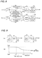
- Fig. 8 is a block diagram illustrating a whole construction of the system according to the second embodiment of the present invention.
- second band enhancing portions (90) and (100) are provided after the matrix portions (70) and (80), respectively, so that the output signal of the system can be enhanced in the spatial frequency range after the gain of the system as a whole is increased in the matrix portions.
- Fig. 9 is a block diagram depicting the construction of the circuits provided after the matrix portion in the second embodiment
- Fig. 9(a) is a block diagram representing the circuit structure of the second band enhancing portions in detail
- Fig. 9(b) is a graph showing the characteristic of the output signal of the second band enhancing portion.
- the system can be suitably applied to special kind of soft ware, such as a movie soft ware, where, for instance, signals in the lower frequency range should be enhanced more.
- the circuit construction for the second band enhancing portions (90) and (100) can be modified in several manners. It may be possible to use a passive circuit constituted of a register and a capacitor as shown in Fig. 9(a) or an active circuit constituted of an operational amplifier and other passive elements for the second band enhancing portion.
- the second band enhancing portion (90) is constituted of a passive filter, i.e. a register (R91), (R92) and a capacitor (C91) as well as the second band enhancing portion (100) on the right side channel.
- the filter has a characteristic that the gain of the signal passing range is almost one (1) and the gain of the signal interrupting range is R92/(R91+R92). Therefore, it is possible to enhance the output signal in the lower frequency range by passing the output signal of the matrix circuit through the filter. It is also possible to adjust the gain of the output signal of the matrix circuit in the middle and higher frequency ranges. Furthermore, it is possible to adjust the gain of the output signal in a particular frequency range independently as occasional demand by using an active circuit.
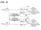
- Fig. 10 is a block diagram showing a third embodiment of the system according to the invention.
- the third embodiment no band enhancing portion (50)(60) is provided in order to make the circuit construction simpler, but the system is constituted such that the channel matrix portions (70)(80), to which the channel signals are inputted, respectively, also work as the band enhancing portion.
- the spatial effect enhancing circuits (30)(40) are provided as well as the other embodiments.
- the system according to the present invention has a function that the original sound signal is enhanced in the lower frequency range, the original sound signal is maintained as it was in the middle frequency range, and the attendance sense and the directivity of sound is improved in the higher frequency range. It is also possible to arrange the system to enhance a particular frequency range in accordance with the sort of the original sound.
- the present invention can be applied to every kind of equipment where the three dimensional image sound is reproduced from stereo signals or encoded signals. Moreover, the present invention can be applied not only to reproduce audio signals but also to record audio signals.
- an excellent three dimensional acoustic sound can be obtained by applying the above explained circuits on the audio stereo signal lines.
- a remarkable effect to reproduce the suitable background sound which has not been realized according to the prior surround technique, can be obtained and the dynamic range of the reproducing sound signal can be enhanced in accordance with the filter-curve characteristic of the system. If the time constant of each element provided in each circuit is adjusted so as to make it suitable for the condition to which the system is applied, an excellent attendance sense of sound and an effective enhancement of the background sound can be obtained.
Landscapes
- Physics & Mathematics (AREA)
- Engineering & Computer Science (AREA)
- Acoustics & Sound (AREA)
- Signal Processing (AREA)
- Stereophonic System (AREA)
- Stereo-Broadcasting Methods (AREA)
Applications Claiming Priority (8)
| Application Number | Priority Date | Filing Date | Title |
|---|---|---|---|
| KR9708472 | 1997-03-13 | ||
| KR1019970008472A KR100233613B1 (ko) | 1997-03-13 | 1997-03-13 | 입체사운드 처리 시스템 |
| KR1019970012151A KR100239918B1 (ko) | 1997-03-28 | 1997-03-28 | 3차원 이미지 스테레오 향상 시스템 |
| KR1019970012152A KR970032268A (ko) | 1997-03-28 | 1997-03-28 | 주파수 선택적 공간감 향상 시스템 |
| KR9712152 | 1997-03-28 | ||
| KR9712151 | 1997-03-28 | ||
| KR1019970015151A KR970058321A (ko) | 1997-04-17 | 1997-04-17 | 주파수 선택적 공간감 향상 및 대역 보강 시스템 |
| KR9715151 | 1997-04-17 |
Publications (3)
| Publication Number | Publication Date |
|---|---|
| EP0865226A2 true EP0865226A2 (de) | 1998-09-16 |
| EP0865226A3 EP0865226A3 (de) | 2002-03-20 |
| EP0865226B1 EP0865226B1 (de) | 2006-12-13 |
Family
ID=27483189
Family Applications (1)
| Application Number | Title | Priority Date | Filing Date |
|---|---|---|---|
| EP97117057A Expired - Lifetime EP0865226B1 (de) | 1997-03-13 | 1997-10-01 | System zur Verbesserung des Raumklangeffektes von Stereoton oder kodierten Tonsignalen |
Country Status (4)
| Country | Link |
|---|---|
| US (1) | US6587565B1 (de) |
| EP (1) | EP0865226B1 (de) |
| JP (1) | JP3663461B2 (de) |
| DE (1) | DE69737087T2 (de) |
Cited By (3)
| Publication number | Priority date | Publication date | Assignee | Title |
|---|---|---|---|---|
| WO2000042818A1 (en) * | 1999-01-11 | 2000-07-20 | Thomson Licensing S.A. | A stereophonic spatial expansion circuit with tonal compensation and active matrixing |
| US6947564B1 (en) | 1999-01-11 | 2005-09-20 | Thomson Licensing | Stereophonic spatial expansion circuit with tonal compensation and active matrixing |
| EP2709380A1 (de) * | 2012-09-18 | 2014-03-19 | Parrot | Aktive Monoblock-Lautsprecherbox, die zur Einzel- oder paarweisen Benutzung konfiguriert werden kann, mit Verstärkung des Stereobilds |
Families Citing this family (16)
| Publication number | Priority date | Publication date | Assignee | Title |
|---|---|---|---|---|
| US5912976A (en) * | 1996-11-07 | 1999-06-15 | Srs Labs, Inc. | Multi-channel audio enhancement system for use in recording and playback and methods for providing same |
| US6373954B1 (en) * | 1997-10-14 | 2002-04-16 | Cirrus Logic, Inc. | Single-chip audio circuitry, method, and systems using the same |
| JP2001069597A (ja) * | 1999-06-22 | 2001-03-16 | Yamaha Corp | 音声処理方法及び装置 |
| US20020118839A1 (en) * | 2000-12-27 | 2002-08-29 | Philips Electronics North America Corporation | Circuit for providing a widened stereo image |
| US7447321B2 (en) * | 2001-05-07 | 2008-11-04 | Harman International Industries, Incorporated | Sound processing system for configuration of audio signals in a vehicle |
| US7177432B2 (en) * | 2001-05-07 | 2007-02-13 | Harman International Industries, Incorporated | Sound processing system with degraded signal optimization |
| US7451006B2 (en) * | 2001-05-07 | 2008-11-11 | Harman International Industries, Incorporated | Sound processing system using distortion limiting techniques |
| US6804565B2 (en) * | 2001-05-07 | 2004-10-12 | Harman International Industries, Incorporated | Data-driven software architecture for digital sound processing and equalization |
| JP4744874B2 (ja) * | 2002-05-03 | 2011-08-10 | ハーマン インターナショナル インダストリーズ インコーポレイテッド | サウンドの検出および特定システム |
| GB2419265B (en) * | 2004-10-18 | 2009-03-11 | Wolfson Ltd | Improved audio processing |
| US8050434B1 (en) * | 2006-12-21 | 2011-11-01 | Srs Labs, Inc. | Multi-channel audio enhancement system |
| JP5908199B2 (ja) * | 2009-05-21 | 2016-04-26 | 株式会社ザクティ | 音響処理装置及び集音装置 |
| US8571232B2 (en) * | 2009-09-11 | 2013-10-29 | Barry Stephen Goldfarb | Apparatus and method for a complete audio signal |
| US8259960B2 (en) * | 2009-09-11 | 2012-09-04 | BSG Laboratory, LLC | Phase layering apparatus and method for a complete audio signal |
| EP2661907B8 (de) | 2011-01-04 | 2019-08-14 | DTS, Inc. | Immersives audiowiedergabesystem |
| US9973851B2 (en) | 2014-12-01 | 2018-05-15 | Sonos, Inc. | Multi-channel playback of audio content |
Family Cites Families (15)
| Publication number | Priority date | Publication date | Assignee | Title |
|---|---|---|---|---|
| JPS51132803A (en) | 1975-04-17 | 1976-11-18 | Nippon Hoso Kyokai <Nhk> | Sound field expander |
| US4356349A (en) * | 1980-03-12 | 1982-10-26 | Trod Nossel Recording Studios, Inc. | Acoustic image enhancing method and apparatus |
| US4748669A (en) | 1986-03-27 | 1988-05-31 | Hughes Aircraft Company | Stereo enhancement system |
| US5222059A (en) * | 1988-01-06 | 1993-06-22 | Lucasfilm Ltd. | Surround-sound system with motion picture soundtrack timbre correction, surround sound channel timbre correction, defined loudspeaker directionality, and reduced comb-filter effects |
| US4932059A (en) * | 1988-01-11 | 1990-06-05 | Fosgate Inc. | Variable matrix decoder for periphonic reproduction of sound |
| US4841572A (en) | 1988-03-14 | 1989-06-20 | Hughes Aircraft Company | Stereo synthesizer |
| US4866774A (en) | 1988-11-02 | 1989-09-12 | Hughes Aircraft Company | Stero enhancement and directivity servo |
| US5172415A (en) | 1990-06-08 | 1992-12-15 | Fosgate James W | Surround processor |
| US5251260A (en) | 1991-08-07 | 1993-10-05 | Hughes Aircraft Company | Audio surround system with stereo enhancement and directivity servos |
| US5333201A (en) * | 1992-11-12 | 1994-07-26 | Rocktron Corporation | Multi dimensional sound circuit |
| DE69433258T2 (de) | 1993-07-30 | 2004-07-01 | Victor Company of Japan, Ltd., Yokohama | Raumklangsignalverarbeitungsvorrichtung |
| JP2924710B2 (ja) * | 1995-04-28 | 1999-07-26 | ヤマハ株式会社 | ステレオ音場拡大装置 |
| US5850453A (en) * | 1995-07-28 | 1998-12-15 | Srs Labs, Inc. | Acoustic correction apparatus |
| US5872851A (en) * | 1995-09-18 | 1999-02-16 | Harman Motive Incorporated | Dynamic stereophonic enchancement signal processing system |
| KR0175515B1 (ko) * | 1996-04-15 | 1999-04-01 | 김광호 | 테이블 조사 방식의 스테레오 구현 장치와 방법 |
-
1997
- 1997-08-28 JP JP24599697A patent/JP3663461B2/ja not_active Expired - Fee Related
- 1997-10-01 DE DE69737087T patent/DE69737087T2/de not_active Expired - Fee Related
- 1997-10-01 EP EP97117057A patent/EP0865226B1/de not_active Expired - Lifetime
- 1997-10-06 US US08/944,211 patent/US6587565B1/en not_active Expired - Fee Related
Cited By (4)
| Publication number | Priority date | Publication date | Assignee | Title |
|---|---|---|---|---|
| WO2000042818A1 (en) * | 1999-01-11 | 2000-07-20 | Thomson Licensing S.A. | A stereophonic spatial expansion circuit with tonal compensation and active matrixing |
| WO2000042819A1 (en) * | 1999-01-11 | 2000-07-20 | Thomson Licensing S.A. | A stereophonic spatial expansion circuit with tonal compensation and active matrixing |
| US6947564B1 (en) | 1999-01-11 | 2005-09-20 | Thomson Licensing | Stereophonic spatial expansion circuit with tonal compensation and active matrixing |
| EP2709380A1 (de) * | 2012-09-18 | 2014-03-19 | Parrot | Aktive Monoblock-Lautsprecherbox, die zur Einzel- oder paarweisen Benutzung konfiguriert werden kann, mit Verstärkung des Stereobilds |
Also Published As
| Publication number | Publication date |
|---|---|
| DE69737087D1 (de) | 2007-01-25 |
| EP0865226A3 (de) | 2002-03-20 |
| HK1016010A1 (en) | 1999-10-22 |
| US6587565B1 (en) | 2003-07-01 |
| EP0865226B1 (de) | 2006-12-13 |
| JP3663461B2 (ja) | 2005-06-22 |
| DE69737087T2 (de) | 2007-07-12 |
| JPH10271600A (ja) | 1998-10-09 |
Similar Documents
| Publication | Publication Date | Title |
|---|---|---|
| EP0865226B1 (de) | System zur Verbesserung des Raumklangeffektes von Stereoton oder kodierten Tonsignalen | |
| US7974425B2 (en) | Sound system and method of sound reproduction | |
| US5850454A (en) | Method and apparatus for spatially enhancing stereo and monophonic signals | |
| US4349698A (en) | Audio signal translation with no delay elements | |
| CN100493235C (zh) | 夏富拉型音响信号处理电路以及方法 | |
| EP1610588B1 (de) | Audio-Signalverarbeitung | |
| US7945054B2 (en) | Method and apparatus to reproduce wide mono sound | |
| US5930733A (en) | Stereophonic image enhancement devices and methods using lookup tables | |
| US6870933B2 (en) | Stereo audio processing device for deriving auxiliary audio signals, such as direction sensing and center signals | |
| JP3513850B2 (ja) | 音像定位処理装置および方法 | |
| US4910778A (en) | Signal enhancement processor for stereo system | |
| GB2419265A (en) | Processing of stereo audio signals | |
| EP1054574A1 (de) | Vorrichtung zur schallbildlokalisierung | |
| JPH10322799A (ja) | ステレオ音像拡大装置 | |
| US5263086A (en) | Audio accessory circuit | |
| KR100424520B1 (ko) | 신호변경회로및방법 | |
| HK1016010B (en) | A system for improving a spatial effect of stereo sound or encoded sound | |
| JP3368835B2 (ja) | 音響信号処理回路 | |
| EP0630168A1 (de) | Dolby-Prologic-Dekodierer | |
| US3050583A (en) | Controllable stereophonic electroacoustic network | |
| JP2946884B2 (ja) | 低音域特性補正回路 | |
| KR100239918B1 (ko) | 3차원 이미지 스테레오 향상 시스템 | |
| JPH05145991A (ja) | 低音域特性補正回路 | |
| KR940000106Y1 (ko) | 초저음 및 입체음향신호 동시처리회로 | |
| Liew et al. | Power Improvement in Crosstalk Cancellation Using Psychoacoustic Frequency Masking |
Legal Events
| Date | Code | Title | Description |
|---|---|---|---|
| PUAI | Public reference made under article 153(3) epc to a published international application that has entered the european phase |
Free format text: ORIGINAL CODE: 0009012 |
|
| AK | Designated contracting states |
Kind code of ref document: A2 Designated state(s): AT BE CH DE DK ES FI FR GB GR IE IT LI LU MC NL PT SE Kind code of ref document: A2 Designated state(s): DE FR GB IT NL |
|
| AX | Request for extension of the european patent |
Free format text: AL;LT;LV;RO;SI |
|
| PUAL | Search report despatched |
Free format text: ORIGINAL CODE: 0009013 |
|
| AK | Designated contracting states |
Kind code of ref document: A3 Designated state(s): AT BE CH DE DK ES FI FR GB GR IE IT LI LU MC NL PT SE |
|
| AX | Request for extension of the european patent |
Free format text: AL;LT;LV;RO;SI |
|
| 17P | Request for examination filed |
Effective date: 20020610 |
|
| AKX | Designation fees paid |
Free format text: DE FR GB IT NL |
|
| 17Q | First examination report despatched |
Effective date: 20041123 |
|
| GRAP | Despatch of communication of intention to grant a patent |
Free format text: ORIGINAL CODE: EPIDOSNIGR1 |
|
| GRAS | Grant fee paid |
Free format text: ORIGINAL CODE: EPIDOSNIGR3 |
|
| GRAA | (expected) grant |
Free format text: ORIGINAL CODE: 0009210 |
|
| AK | Designated contracting states |
Kind code of ref document: B1 Designated state(s): DE FR GB IT NL |
|
| REG | Reference to a national code |
Ref country code: GB Ref legal event code: FG4D |
|
| REF | Corresponds to: |
Ref document number: 69737087 Country of ref document: DE Date of ref document: 20070125 Kind code of ref document: P |
|
| REG | Reference to a national code |
Ref country code: HK Ref legal event code: GR Ref document number: 1016010 Country of ref document: HK |
|
| ET | Fr: translation filed | ||
| PLBE | No opposition filed within time limit |
Free format text: ORIGINAL CODE: 0009261 |
|
| STAA | Information on the status of an ep patent application or granted ep patent |
Free format text: STATUS: NO OPPOSITION FILED WITHIN TIME LIMIT |
|
| 26N | No opposition filed |
Effective date: 20070914 |
|
| NLV4 | Nl: lapsed or anulled due to non-payment of the annual fee |
Effective date: 20080501 |
|
| PG25 | Lapsed in a contracting state [announced via postgrant information from national office to epo] |
Ref country code: DE Free format text: LAPSE BECAUSE OF NON-PAYMENT OF DUE FEES Effective date: 20080501 |
|
| REG | Reference to a national code |
Ref country code: FR Ref legal event code: ST Effective date: 20080630 |
|
| PG25 | Lapsed in a contracting state [announced via postgrant information from national office to epo] |
Ref country code: NL Free format text: LAPSE BECAUSE OF NON-PAYMENT OF DUE FEES Effective date: 20080501 |
|
| PG25 | Lapsed in a contracting state [announced via postgrant information from national office to epo] |
Ref country code: FR Free format text: LAPSE BECAUSE OF NON-PAYMENT OF DUE FEES Effective date: 20071031 |
|
| PGFP | Annual fee paid to national office [announced via postgrant information from national office to epo] |
Ref country code: GB Payment date: 20081001 Year of fee payment: 12 |
|
| PG25 | Lapsed in a contracting state [announced via postgrant information from national office to epo] |
Ref country code: IT Free format text: LAPSE BECAUSE OF NON-PAYMENT OF DUE FEES Effective date: 20071001 |
|
| PG25 | Lapsed in a contracting state [announced via postgrant information from national office to epo] |
Ref country code: GB Free format text: LAPSE BECAUSE OF NON-PAYMENT OF DUE FEES Effective date: 20091001 |